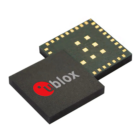
Ublox LEA-M8S Quick setup guide

LEA-M8S / LEA-M8T - Hardware integration manual
UBX-15030060 - R06 Page 2 of 33
Production information Document information
Document information
Title
LEA-M8S / LEA-M8T
Subtitle
u-blox M8 concurrent GNSS modules
Document type
Hardware integration manual
Document number
UBX-15030060
Revision and date
R06
5-May-2020
Document status
Production information
Product status
Corresponding content status
In Development /
Prototype
Objective Specification
Target values. Revised and supplementary data will be published later.
Engineering Sample
Advance Information
Data based on early testing. Revised and supplementary data will be published later.
Initial Production
Early Production Information
Data from product verification. Revised and supplementary data may be published later.
Mass Production /
End of Life
Production Information
Document contains the final product specification.
This document applies to the following products:
Product name
Type number
Firmware version
PCN reference
LEA-M8S
LEA-M8S-0-10
ROM SPG 3.01
UBX-16012752
LEA-M8T
LEA-M8T-0-10
Flash FW 3.01 TIM 1.10
UBX-16004907
LEA-M8T
LEA-M8T-1-00
Flash FW 3.01 TIM 1.11
u-blox or third parties may hold intellectual property rights in the products, names, logos and designs included in this
document. Copying, reproduction, modification or disclosure to third parties of this document or any part thereof is only
permitted with the express written permission of u-blox.
The information contained herein is provided “as is” and u-blox assumes no liability for its use. No warranty, either express or
implied, is given, including but not limited to, with respect to the accuracy, correctness, reliability and fitness for a particular
purpose of the information. This document may be revised by u-blox at any time without notice. For the most recent
documents, visit www.u-blox.com.
Copyright © u-blox AG.

LEA-M8S / LEA-M8T - Hardware integration manual
UBX-15030060 - R06 Page 3 of 33
Production information Contents
Contents
Document information................................................................................................................................2
Contents ..........................................................................................................................................................3
1Hardware description...........................................................................................................................5
1.1 Overview........................................................................................................................................................ 5
1.2 Configuration ............................................................................................................................................... 5
1.3 Connecting power ....................................................................................................................................... 5
1.3.1 VCC: Main supply voltage .................................................................................................................5
1.3.2 V_BCKP: Backup supply voltage ......................................................................................................5
1.3.3 VDD_USB: USB interface power supply ......................................................................................... 6
1.3.4 VCC_RF: Output voltage RF section...............................................................................................6
1.3.5 V_ANT: Antenna supply ....................................................................................................................6
1.4 Interfaces......................................................................................................................................................6
1.4.1 UART .....................................................................................................................................................6
1.4.2 USB ........................................................................................................................................................6
1.4.3 Display data channel (DDC) .............................................................................................................. 7
1.4.4 SPI (LEA-M8T only) ............................................................................................................................ 7
1.4.5 TX_READY............................................................................................................................................8
1.5 I/O pins...........................................................................................................................................................8
1.5.1 RESET_N: Reset.................................................................................................................................. 8
1.5.2 EXTINT: External interrupt ...............................................................................................................8
1.5.3 SAFEBOOT_N ......................................................................................................................................8
1.5.4 D_SEL: Interface select (LEA-M8T only)........................................................................................9
1.5.5 Antenna open circuit detection (ANT_DET_N)............................................................................. 9
1.5.6 TIMEPULSE..........................................................................................................................................9
1.5.7 TIMEPULSE 2 (LEA-M8T only) ........................................................................................................ 9
1.6 Electromagnetic interference on I/O lines ............................................................................................. 9
2Design..................................................................................................................................................... 11
2.1 Pin description ...........................................................................................................................................11
2.1.1 Pin name changes.............................................................................................................................12
2.2 Minimal design...........................................................................................................................................13
2.3 Footprint and paste mask.......................................................................................................................13
2.4 Antenna.......................................................................................................................................................14
2.4.1 Antenna design with passive antenna .........................................................................................14
2.4.2 Active antenna design .....................................................................................................................15
2.4.3 Power and short detection antenna supervisor .........................................................................17
2.4.4 Power, short and open detection antenna supervisor ..............................................................18
2.5 Layout design-in: Thermal management.............................................................................................19
3Migration to u-blox M8 modules.................................................................................................... 20
3.1 Migrating u-blox 6 designs to u-blox M8 module ...............................................................................20
3.2 Hardware migration LEA-6N -> LEA-M8S ...........................................................................................20
LEA-M8S / LEA-M8T - Hardware integration manual
UBX-15030060 - R06 Page 4 of 33
Production information Contents
3.3 Hardware migration LEA-6T -> LEA-M8T ...........................................................................................21
3.4 Software migration...................................................................................................................................21
4Product handling................................................................................................................................. 22
4.1 Packaging, shipping, storage and moisture preconditioning ..........................................................22
4.2 Soldering .....................................................................................................................................................22
4.3 EOS/ESD/EMI precautions......................................................................................................................25
4.4 Applications with cellular modules........................................................................................................28
Appendix ....................................................................................................................................................... 30
AGlossary ................................................................................................................................................. 30
BRecommended parts ......................................................................................................................... 30
Related documents ................................................................................................................................... 32
Revision history.......................................................................................................................................... 32
Contact.......................................................................................................................................................... 33

LEA-M8S / LEA-M8T - Hardware integration manual
UBX-15030060 - R06 Hardware description Page 5 of 33
Production information
1Hardware description
1.1 Overview
LEA-M8S and LEA-M8T are concurrent GNSS positioning modules featuring the high performance
u-blox M8 positioning engine. They are easy to integrate and combine exceptional positioning
performance with highly flexible power, design, and connectivity options. SMT pads allow fully
automated assembly with standard pick-and-place and reflow-soldering equipment for cost-efficient,
high-volume production enabling short time-to-market.
☞For specific product features, see LEA-M8S Data sheet [1] and NEO / LEA-M8T Data sheet [2].
☞To determine which u-blox product best meets your needs, see the product selector tables on the
u-blox website.
1.2 Configuration
The configuration settings can be modified using UBX protocol configuration messages, for more
information see the u-blox 8 / u-blox M8 Receiver Description Including Protocol Specification [3]. The
modified settings remain effective until power-down or reset. If these settings have been stored in
Battery Backed RAM (BBR), the modified configuration will be retained, as long as the backup battery
supply is not interrupted.
1.3 Connecting power
The LEA-M8S and LEA-M8T positioning modules have up to three power supply pins: VCC, V_BCKP
and VDD_USB.
1.3.1 VCC: Main supply voltage
The VCC pin provides the main supply voltage. During operation, the current drawn by the module can
vary by some orders of magnitude, especially if enabling low-power operation modes. For this reason,
it is important that the supply circuitry is able to support the peak power for a short time (see the
LEA-M8S Data sheet
[1] and the NEO / LEA-M8T Data sheet
Error! Reference source not found. for
etailed specifications).
☞When switching from backup mode to normal operation or at start-up, the LEA-M8S and LEA-
M8T modules must charge the internal capacitors in the core domain. In certain situations, this
can result in a significant current draw. For low-power applications using power save and backup
modes, it is important that the power supply or low ESR capacitors at the module input can deliver
this current/charge.
☞Use a proper GND concept. Do not use any resistors or coils in the power line.
1.3.2 V_BCKP: Backup supply voltage
If the module supply has a power failure, the V_BCKP pin supplies the real-time clock (RTC) and
battery-backed RAM (BBR). Use of valid time and the GNSS orbit data at start-up will improve the
GNSS performance, that is, it enables hot and warm starts. If no backup battery is connected, the
module performs a cold start at power-up.
☞Avoid high resistance on the V_BCKP line: During the switch from main supply to backup supply,
a short current adjustment peak can cause high voltage drop on the pin with possible
malfunctions.

LEA-M8S / LEA-M8T - Hardware integration manual
UBX-15030060 - R06 Hardware description Page 6 of 33
Production information
☞If no backup supply voltage is available, connect the V_BCKP pin to VCC.
☞As long as the LEA-M8S and LEA-M8T modules are supplied via the VCC, the backup battery is
disconnected from the RTC and the BBR to avoid unnecessary battery drain (see Figure 1). In this
case, VCC supplies power to the RTC and BBR.
Figure 1: Backup battery and voltage (for exact pin orientation, see the LEA-M8S Data sheet [1] and the NEO/LEA-M8T Data
sheet
[2]
1.3.3 VDD_USB: USB interface power supply
VDD_USB supplies the USB interface. If the USB interface is not used, the VDD_USB pin must be
connected to GND. For more information about correctly handling the VDD_USB pin, see section 1.4.
1.3.4 VCC_RF: Output voltage RF section
TheVCC_RF pin can supply an active antenna or external LNA. For more information, see section 2.4.
1.3.5 V_ANT: Antenna supply
The V_ANT pin is available to provide antenna bias voltage to supply an optional external active
antenna. For more information, see section 2.4.
☞If not used, connect the V_ANT pin to GND.
1.4 Interfaces
1.4.1 UART
The LEA-M8S and LEA-M8T positioning modules include a universal asynchronous receiver
transmitter (UART) serial interface RXD/TXD, which supports configurable baud rates. The baud
rates supported are specified in the LEA-M8S Data sheet [1] and the NEO / LEA-M8T Data sheet [2]
The signal output and input levels are 0 V to VCC. An interface based on RS232 standard levels
(+/- 12 V) can be implemented using level shifters such as Maxim MAX3232. Hardware handshake
signals and synchronous operation are not supported.
1.4.2 USB
A USB version 2.0 FS (full speed, 12 Mb/s) compatible interface is available for communication as an
alternative to the UART. The USB_DP integrates a pull-up resistor to signal a full-speed device to the
host. The VDD_USB pin supplies the USB interface.
u-blox provides Microsoft® certified USB drivers for Windows Vista, Windows 7, Windows 8 and
Windows 10 operating systems. These drivers are available at our website at www.u-blox.com.
USB external components

LEA-M8S / LEA-M8T - Hardware integration manual
UBX-15030060 - R06 Hardware description Page 7 of 33
Production information
The USB interface requires some external components to implement the physical characteristics
required by the USB 2.0 specification. These external components are shown in Figure 2 and listed in
Table 1. To comply with USB specifications, VBUS must be connected through an LDO (U1) to pin
VDD_USB on the module.
The USB device is self-powered, the power supply (VCC) can be turned off and the digital block is not
powered. In this case, since VBUS is still available, the USB host still receives the signal indicating that
the device is present and ready to communicate. This should be avoided by disabling the LDO (U1)
using the enable signal (EN) of the VCC-LDO or the output of a voltage supervisor. Depending on the
characteristics of the LDO (U1), it is recommended to add a pull-down resistor (R11) at its output to
ensure VDD_USB is not floating if the LDO (U1) is disabled or the USB cable is not connected, that is,
VBUS is not supplied.
☞USB bus powered is not supported.
Module
VDD_USB
LDO
VDD_USB
R4
USB_DP
USB_DM
R5
C24 C23
D2
VBUS
DP
DM
GND
USB Device Connector
U1
EN R11
EN
Figure 2: USB interface
Name
Component
Function
Comments
U1
LDO
Regulates VBUS (4.4 … 5.25 V) down
to a voltage of 3.3 V.
Almost no current requirement (~1 mA).
C23,
C24
Capacitors
Required according to the specification of LDO U1.
D2
Protection diodes
Protect circuit from overvoltage /
ESD when connecting.
Use low capacitance ESD protection such as ST
Microelectronics USBLC6-2.
R4, R5
Serial termination
resistors
Establish a full-speed driver
impedance of 28 …44
A value of 27 is recommended.
R11
Resistor
100 kis recommended for USB self-powered setup.
For bus-powered setup, R11 can be ignored.
Table 1: Summary of USB external components
1.4.3 Display data channel (DDC)
An I2C-compatible display data channel (DDC) interface is available for serial communication with an
external host CPU. The interface only supports operation in slave mode (master mode is not
supported). The DDC protocol and electrical interface are fully compatible with the fast mode of the
I2C industry standard. DDC pins SDA and SCL have internal pull-up resistors.
For more information about the DDC implementation, see the u-blox 8 / u-blox M8 Receiver
Description Including Protocol Specification [3]. For bandwidth information, see the LEA-M8S Data
sheet [1] and the NEO / LEA-M8T Data sheet
[2]. For timing parameters, consult the I2C-bus
specification [6].
☞The u-blox M8 DDC interface supports serial communication with most u-blox cellular modules.
See the specification of the applicable cellular module to confirm compatibility.
1.4.4 SPI (LEA-M8T only)
An SPI interface is available for communication to a host CPU.

LEA-M8S / LEA-M8T - Hardware integration manual
UBX-15030060 - R06 Hardware description Page 8 of 33
Production information
☞SPI is not available in the default configuration because its pins are shared with the UART and DDC
interfaces. The SPI interface can be enabled by connecting D_SEL to ground. For speed and clock
frequency, see the NEO / LEA-M8T Data sheet
[2].
1.4.5 TX_READY
The TX_READY function is used to indicate when the receiver has data to transmit. A listener can wait
on the TX_READY signal instead of polling the DDC or SPI interfaces. The UBX-CFG-PRT message lets
you configure the polarity and the number of bytes in the buffer before the TX_READY signal goes
active. The TX_READY function can be mapped to TXD (PIO 06). The TX_READY function is disabled
by default.
☞The TX_READY functionality can be enabled and configured by AT commands sent to the u-blox
cellular module supporting the feature. For more information, see the GPS Implementation and
Aiding Features in u-blox Wireless Modules [7].
1.5 I/O pins
1.5.1 RESET_N: Reset
Driving RESET_N low activates a hardware reset of the system. Use this pin only to reset the module.
Do not use RESET_N to turn the module on and off, since the reset state increases power
consumption. With LEA-M8S and LEA-M8T module RESET_N is an input only.
☞The RTC time is also reset (but not BBR).
1.5.2 EXTINT: External interrupt
EXTINT0 and EXTINT1 are external interrupt pins with fixed input voltage thresholds with respect to
VCC (see the LEA-M8S Data sheet
[1] and the NEO / LEA-M8T Data sheet
[2] for more information).
They can be used for wake-up functions in power save mode and for aiding. Leave open if unused.
The EXTINT0 pin can also be configured as a generic PIO (PIO13).
The EXTINT1 pin can also be configured as an active antenna open circuit detection function
(ANT_DET_N). For further information see sections 1.5.5 and 2.4.4.
Power control
The power control feature allows overriding the automatic active/inactive cycle of power save mode.
The state of the receiver can be controlled through the EXTINT0 and EXTINT1 pin. The receiver can
also be forced OFF using EXTINT0 and EXTINT1 when power save mode is not active.
Frequency aiding
The EXTINT0 and EXTINT1 pins can be used to supply time or frequency aiding data to the receiver.
For time aiding, hardware time synchronization can be achieved by connecting an accurate time pulse
to the EXTINT0 pin.
Frequency aiding can be implemented by connecting a periodic rectangular signal with a frequency up
to 500 kHz and arbitrary duty cycle (low/high phase duration must not be shorter than 50 ns) to the
EXTINT0 pin. Provide the applied frequency value to the receiver using UBX messages.
1.5.3 SAFEBOOT_N
The SAFEBOOT_N pin is for future service, updates and reconfiguration.
☞Do not pull low during reset.

LEA-M8S / LEA-M8T - Hardware integration manual
UBX-15030060 - R06 Hardware description Page 9 of 33
Production information
1.5.4 D_SEL: Interface select (LEA-M8T only)
The D_SEL pin selects the available interfaces. SPI cannot be used simultaneously with UART/DDC.
If open, UART and DDC are available. If pulled low, the SPI interface is available. See the NEO / LEA-
M8T Data sheet [2].
1.5.5 Antenna open circuit detection (ANT_DET_N)
ANT_DET_N on EXTINT1 PIO14 is an input pin used to report whether an external circuit has detected
an external antenna or not.
"low" = Antenna detected (antenna consumes current)
"high" = Antenna not detected (no current drawn). This functionality is by default disabled.
For more information, see section 2.4.4.
Antenna supervision is configurable using message UBX-CFG-ANT.
☞Refer to the u-blox 8 / u-blox M8 Receiver Description Including Protocol Specification Error!
eference source not found. for information about further settings.
1.5.6 TIMEPULSE
A configurable time pulse signal is available on LEA-M8S and LEA-M8T. By default, the time pulse
signal is configured to one pulse per second. For more information, see the u-blox 8 / u-blox M8
Receiver Description Including Protocol Specification [3].
1.5.7 TIMEPULSE 2 (LEA-M8T only)
A configurable TIMEPULSE2 signal is available on LEA-M8T module only. For more information see
the u-blox 8 / u-blox M8 Receiver Description Including Protocol Specification [3].
1.6 Electromagnetic interference on I/O lines
Any I/O signal line with a length greater than approximately 3 mm can act as an antenna and may pick
up arbitrary RF signals, transferring them as noise into the GNSS receiver. This specifically applies to
unshielded lines, in which the corresponding GND layer is remote or missing entirely, and to lines close
to the edges of the printed circuit board.
If, for example, a cellular signal radiates into an unshielded high-impedance line, it is possible to
generate noise in the order of volts and not only distort receiver operation but also damage it
permanently. On the other hand, noise generated at the I/O pins will emit from unshielded I/O lines.
Receiver performance may be degraded if this noise is coupled to the GNSS antenna (see Figure 18).
To avoid interference by improperly shielded lines, it is recommended to use resistors (e.g. R>20 ),
ferrite beads (for example, BLM15HD102SN1) or inductors (for example, LQG15HS47NJ02) on the
I/O lines in series. Choose these components with care because they will also affect the signal rise
times.
Figure 3 shows an example of EMI protection measures on the RX/TX line using a ferrite bead. More
information can be found in section 4.3.

LEA-M8S / LEA-M8T - Hardware integration manual
UBX-15030060 - R06 Hardware description Page 10 of 33
Production information
Figure 3: EMI Precautions

LEA-M8S / LEA-M8T - Hardware integration manual
UBX-15030060 - R06 Design Page 11 of 33
Production information
2Design
2.1 Pin description
Function
Pin
No.
I/O
Description
Remarks
Power
VCC
6
I
Supply voltage
Provide clean and stable supply.
GND
7, 13, 14,
15, 17
-
Ground
Assure a good GND connection to all GND pins of
the module.
VCC_OUT
8
O
Output voltage (VCC)
Leave open if not used.
V_BCKP
11
I
Backup supply voltage
It is recommended to connect a backup supply
voltage to V_BCKP in order to enable warm and
hot start features on the positioning modules.
Otherwise, connect to VCC.
VDD_USB
24
I
USB power supply
To use the USB interface connect this pin to 3.0 –
3.6 V.
If no USB serial port used connect to GND.
Antenna
RF_IN
16
I
GNSS signal input from
antenna
Use a controlled impedance transmission line of
50 to connect to RF_IN.
VCC_RF
18
O
Output voltage RF
section
Can be used to power external LNA or an external
active antenna (VCC_RF connected to V_ANT
with 10 ). The max power consumption of the
antenna must not exceed the data sheet
specification of the module. Leave open if not
used.
V_ANT
19
I
Antenna bias voltage
Connect to GND (or leave open) if passive antenna
is used. If an active antenna is used, add a 10
resistor in front of V_ANT input to the antenna
bias voltage or VCC_RF.
EXTINT1
20
I
Ext. interrupt
Ext. interrupt pin. Int. pull-up resistor to VCC. Can
be configured as open circuit detection
(ANT_DET_N). Leave open if not used.
UART
TXD 3
(LEA-M8S)
TXD / SPI MISO
(LEA-M8T)
O
TXD
Serial port TXD
O
TXD
SPI MISO
Serial port TXD if D_SEL =1 (or open)
SPI MISO if D_SEL = 0
RXD 4
(LEA-M8S)
RXD / SPI MOSI
(LEA-M8T)
I
RXD
Serial port if RXD
I
RXD
SPI MOSI
Serial port if RXD D_SEL =1 (or open)
SPI MOSI if D_SEL = 0
USB
USB_DM
25
I/O
USB I/O line
USB2.0 bidirectional communication pin. Leave
open if unused. For implementations, see section
1.4.
USB_DP
26
I/O
USB I/O line
System
RESET_N
10
I
Hardware Reset
(Active Low)
Leave open if not used. Do not drive high.
TIMEPULSE
28
O
Timepulse 1
Configurable timepulse 1 signal (one pulse per
second by default). Leave open if not used.
TP2/SAFEBOOT_
N
(LEA-M8T)
SAFEBOOT_N
(LEA-M8S)
12
I/O
Safeboot_N / Timepulse
2
Configurable timepulse signal. Must not be held
LO during start-up.
I/O
Safeboot_N
Must not be held LO during start-up.
EXTINT0 / PIO13
27
I /
(O)
Ext. interrupt / PIO13
Ext. interrupt pin. Int. pull-up resistor to VCC.
Leave open if unused. The pin can also be used as
a generic PIO (PIO13).

LEA-M8S / LEA-M8T - Hardware integration manual
UBX-15030060 - R06 Design Page 12 of 33
Production information
Function
Pin
No.
I/O
Description
Remarks
SDA 1
(LEA-M8S)
SDA /SPI CS_N
(LEA-M8T)
I/O
SDA
DDC data
I/O
SDA
SPI CS_N
DDC data if D_SEL =1 (or open)
SPI chip select if D_SEL = 0
SCL 2
(LEA-M8S)
SCL / SPI CLK
(LEA-M8T)
I/O
SCL
DDC clock
I/O
SCL
SPI CLK
DDC clock if D_SEL =1 (or open)
SPI clock if D_SEL = 0
RESERVED 5
(LEA-M8S)
D_SEL
(LEA-M8T)
I
Reserved
Leave open
I
Interface select
D_SEL = 0 -> SPI, D_SEL =1 (or open) -> DDC
Reserved
9, 21, 22,
23
-
Reserved
Leave open
Table 2: Pinout LEA-M8S / LEA-M8T
2.1.1 Pin name changes
Selected pin names have been updated to agree with a common naming convention across u-blox
modules. The pins have not changed their operation and are the same physical hardware but with
updated names. The table below lists the pins that have changed their name along with their old and
new names.
No
Previous name
New name
3
TxD (LEA-M8S)
TXD
3
TxD (LEA-M8T)
TXD / SPI MISO
4
RxD (LEA-M8S)
RXD
4
RxD (LEA-M8T)
RXD / SPI MOSI
12
Reserved (LEA-M8S)
SAFEBOOT_N
20
AADET_N
EXTINT1
Table 3: Pin name changes

LEA-M8S / LEA-M8T - Hardware integration manual
UBX-15030060 - R06 Design Page 13 of 33
Production information
2.2 Minimal design
This is a minimal setup for a GNSS receiver with a LEA-M8S and LEA-M8T module:
Passive antenna used
No backup battery
UART for communication
Figure 4: LEA-M8S / LEA-M8T passive antenna design
☞For active antenna design, see section 2.4.
2.3 Footprint and paste mask
Figure 5 describes the footprint and provides recommendations for the paste mask for the LEA-M8S
and LEA-M8T modules. These are recommendations only and not specifications. Note that the
copper and solder masks have the same size and position.
To improve the wetting of the half vias, reduce the amount of solder paste under the module and
increase the volume outside of the module by defining the dimensions of the paste mask to form a T-
shape (or equivalent) extending beyond the copper mask. For the stencil thickness, see Figure 6.

LEA-M8S / LEA-M8T - Hardware integration manual
UBX-15030060 - R06 Design Page 14 of 33
Production information
17.0mm[669 mil]
22.4mm[881.9 mil]
1.0mm
[39mil]
0.8mm
[31.5mil]
2.45mm
[96.5mil]
1.1mm
[43mil]
3.0mm
[118 mil]
2.15mm
[84.5 mil]
0.8mm
[31.5mil]
Figure 5: LEA-M8S and LEA-M8T footprint
Figure 6: LEA-M8S and LEA-M8T paste mask
2.4 Antenna
☞For exact pin orientation in any design, see the LEA-M8S Data sheet [1] and the NEO / LEA-M8T
Data sheet [2].
☞For recommended parts, see Appendix B.
2.4.1 Antenna design with passive antenna
A design using a passive antenna requires more attention to the layout of the RF section. Typically, a
passive antenna is located near electronic components; therefore, take care to reduce electrical noise
that may interfere with the antenna performance. Passive antennas do not require a DC bias voltage
and can be directly connected to the RF input pin RF_IN. Sometimes they may also need a passive
matching network to match the impedance to 50 .
☞Use an antenna that has sufficient bandwidth to receive all GNSS constellations. For
recommended parts, see Appendix B.
Minimal setup with a good patch antenna
Figure 7 shows a minimal setup for a design with a good GNSS patch antenna.

LEA-M8S / LEA-M8T - Hardware integration manual
UBX-15030060 - R06 Design Page 15 of 33
Production information
Figure 7: Module design with passive antenna
Setup for best performance with passive antenna
Figure 8 shows a design using an external LNA to increase the sensitivity for best performance with
passive antenna.
Figure 8: Module design with passive antenna and an external LNA
The VCC_RF output can be used to supply the LNA with a filtered supply voltage.
☞A standard GNSS LNA has enough bandwidth to amplify GPS / Galileo / GLONASS and BeiDou
signals.
2.4.2 Active antenna design
Active antennas have an integrated low-noise amplifier. Active antennas require a power supply that
will contribute to the total GNSS system power consumption budget with additional 5 to 20 mA
typically.
If the customers do not want to make use of the internal antenna supervisor and the supply voltage
of the LEA-M8S and LEA-M8T module matches the supply voltage of the antenna (for example, 3.0

LEA-M8S / LEA-M8T - Hardware integration manual
UBX-15030060 - R06 Design Page 16 of 33
Production information
V), they can use the filtered supply voltage VCC_RF output to supply the antenna (see Figure 9). This
design is used for modules in combination with active antenna.
In case of different supply voltage, use a filtered external supply, see Figure 10.
Active antenna design using VCC_RF pin to supply the active antenna
Figure 9: Active antenna design, external supply from VCC_RF
Active antenna design powered from external supply
Figure 10 shows a design with a direct externally powered active antenna.
This circuit has to be used if the active antenna has a different supply voltage than the VCC_RF (for
example, if a 5 V active antenna is used).
Figure 10: Active antenna design, direct external supply
☞In case VCC_RF voltage does not match with the antenna supply voltage, use a filtered external
supply as shown in Figure 10.
Antenna design with active antenna using antenna supervisor
An active antenna supervisor provides the means to check the antenna for open and short circuits
and to shut off the antenna supply if a short circuit is detected. The antenna supervisor is configured
using serial port UBX binary protocol message. Once enabled, the active antenna supervisor produces
status messages, reporting in NMEA and/or UBX binary protocol.

LEA-M8S / LEA-M8T - Hardware integration manual
UBX-15030060 - R06 Design Page 17 of 33
Production information
The current active antenna status can be determined by polling the UBX-MON-HW monitor
command. If an antenna is connected, the initial state after power-up is “Active Antenna OK.”
The module firmware supports an active antenna supervisor circuit, which is connected to the
ANT_DET_N pin. For an example of an open circuit detection circuit, see Figure 13.
"high" = Antenna detected (antenna consumes current)
"low" = Antenna not detected (no current drawn)
Status reporting
At startup, and on every change of the antenna supervisor configuration, the LEA-M8S module will
output an NMEA ($GPTXT) or UBX (INF-NOTICE) message with the internal status of the antenna
supervisor (disabled, short detection only, enabled).
Abbreviation
Description
AC
Active antenna control enabled
SD
Short circuit detection Enabled
OD
Open circuit detection enabled
PDoS
Short circuit power down logic enabled
SR
Automatic recovery from short state
Table 4: Active antenna supervisor message on startup (UBX binary protocol)
☞To activate the antenna supervisor, use the UBX-CFG-ANT message. For further information,
refer to the u-blox 8 / u-blox M8 Receiver Description Including Protocol Specification [3].
Similar to the antenna supervisor configuration, the status of the antenna supervisor will be reported
in an NMEA ($GPTXT) or UBX (INF-NOTICE) message at start-up and on every change.
2.4.3 Power and short detection antenna supervisor
If a suitably dimensioned R_BIAS series resistor is placed in front of the V_ANT pin, a short circuit can
be detected in the antenna supply. The detection happens inside the u-blox M8 module, after which
the antenna supply voltage will be immediately shut down. Afterwards, periodic attempts to re-
establish antenna power are made by default.
An internal switch (under control of the receiver) can turn off the supply to the external antenna
whenever it is not needed. This feature helps to reduce power consumption in power save mode.
☞To configure the antenna supervisor, use the UBX-CFG-ANT message. For further information,
see the u-blox 8 / u-blox M8 Receiver Description Including Protocol Specification [3].
⚠Short circuits on the antenna input without limitation (R_BIAS) of the current can result in
permanent damage to the receiver! Therefore, it is mandatory to implement an R_BIAS in all risk
applications, such as in situations where the antenna can be disconnected by the end-user or the
antenna cables are long.
☞In case VCC_RF voltage does not match with the antenna supply voltage, use a filtered external
supply as shown in Figure 12.
Supply from VCC_RF
Figure 11 shows an active antenna supplied from the LEA-M8S / LEA-M8T module.
LEA-M8S module includes a built in antenna bias supply for nominal 3 V antennas enabled by linking
the filtered VCC_RF supply output pin to the V_ANT antenna supply input pin with a 10 Ohm resistor
in series. The module then controls the power supply to the antenna, applying power whenever the
receiver is active and removing power during power-save idle times and if a short-circuit is detected.

LEA-M8S / LEA-M8T - Hardware integration manual
UBX-15030060 - R06 Design Page 18 of 33
Production information
Short-circuit is detected if the voltage at the antenna supply falls close to zero and is indicated as an
alarm in message MON-HW.
Figure 11: Module design with active antenna, internal supply from VCC_RF
External supply
Figure 12 shows an externally powered active antenna design.
Since the external bias voltage is fed into the most sensitive part of the receiver (the RF input), this
supply should be free of noise. Usually, low frequency analog noise is less critical than digital noise of
spurious frequencies with harmonics up to the GPS/QZSS band of 1.575 GHz, GLONASS band of
1.602 GHz and BeiDou band at 1.561 GHz. Therefore, it is not recommended to use digital supply nets
to feed the V_ANT pin.
Figure 12: Module design with active antenna, external supply
2.4.4 Power, short and open detection antenna supervisor
Optionally the ANT_DET_N pin may be reassigned to antenna supervision, allowing an external circuit
to indicate to the module that the antenna is open-circuit. This condition is reported by the module in
message MON-HW. Calculate the threshold current using Equation 1.

LEA-M8S / LEA-M8T - Hardware integration manual
UBX-15030060 - R06 Design Page 19 of 33
Production information
Figure 13: Schematic of open circuit detection
RFVcc
Rbias
RR R
I_
32 2
Equation 1: Calculation of threshold current for open circuit detection
☞If the antenna supply voltage is not derived from VCC_RF, do not exceed the maximum voltage
rating of ANT_DET_N.
2.5 Layout design-in: Thermal management
During design-in do not place the module near sources of heating or cooling. The receiver oscillator is
sensitive to sudden changes in ambient temperature which can adversely impact satellite signal
tracking. Sources can include co-located power devices, cooling fans or thermal conduction via the
PCB. Take into account the following questions when designing in the module.
Is the receiver placed away from heat sources?
Is the receiver placed away from air-cooling sources?
Is the receiver shielded by a cover/case to prevent the effects of air currents and rapid
environmental temperature changes?

LEA-M8S / LEA-M8T - Hardware integration manual
UBX-15030060 - R06 Migration to u-blox M8 modules Page 20 of 33
Production information
3Migration to u-blox M8 modules
3.1 Migrating u-blox 6 designs to u-blox M8 module
u-blox is committed to ensuring that products in the same form factor are backwards compatible over
several technology generations. The utmost care has been taken to ensure there is no negative
impact on function or performance and to make u-blox M8 modules as fully compatible with previous
generation modules as possible. If using BeiDou, check the bandwidth of the external RF components
and the antenna. For information about power consumption, see the LEA-M8S Data sheet [1] and the
NEO / LEA-M8T Data sheet
[2]. It is highly advisable that customers consider a design review with the
u-blox support team to ensure the compatibility of key functionalities.
☞Selected pin names have been updated to agree with a common naming convention across u-blox
modules. The pins have not changed their operation and are the same physical hardware but with
updated names.
3.2 Hardware migration LEA-6N -> LEA-M8S
Pin
LEA-6N
LEA-M8S
Remarks for migration
Pin name
Typical assignment
Pin name
Typical assignment
1
SDA
DDC data
SDA
DDC data
No difference
2
SCL
DDC clock
SCL
DDC clock
No difference
3
TxD
Serial port
TXD
Serial port
No difference
4
RxD
Serial port
RXD
Serial port
No difference
5
NC
Not connected
Reserved
Not connected
No difference
6
VCC
Supply voltage
VCC
Supply voltage
No difference
7
GND
Ground (digital)
GND
Ground (digital)
No difference
8
VCC_OUT
Output voltage
VCC_OUT
Output voltage
No difference
9
NC
Not connected
Reserved
Not connected
No difference
10
RESET_N
External reset
RESET_N
External reset
No difference
11
V_BCKP
Backup voltage supply
V_BCKP
Backup voltage supply
If this was connected to
GND on u-blox 6 module,
OK to do the same in M8.
12
Reserved
SAFEBOOT_N,
Do not drive low
SAFEBOOT_N
Do not drive low
No difference
13
GND
Ground
GND
Ground
No difference
14
GND
Ground
GND
Ground
No difference
15
GND
Ground
GND
Ground
No difference
16
RF_IN
GNSS signal input
RF_IN
GNSS signal input
No difference
17
GND
Ground
GND
Ground
No difference
18
VCC_RF
Output voltage RF section
VCC_RF
Output voltage RF section
No difference
19
V_ANT
Antenna bias voltage
V_ANT
Antenna bias voltage
No difference
20
AADET_N
Active antenna detect
EXTINT1
Active antenna detect
No difference
21
Reserved
Not connected
Reserved
Not connected
No difference
22
Reserved
Not connected
Reserved
Not connected
No difference
23
Reserved
Not connected
Reserved
Not connected
No difference
24
VDD_USB
USB supply
VDD_USB
USB supply
No difference
25
USB_DM
USB data
USB_DM
USB data
No difference
26
USB_DP
USB data
USB_DP
USB data
No difference
This manual suits for next models
2
Table of contents
Other Ublox Receiver manuals

Ublox
Ublox NEO-D9C Use and care manual

Ublox
Ublox MAX-M10S Use and care manual

Ublox
Ublox NEO-M9N Use and care manual

Ublox
Ublox ZED-F9R Use and care manual

Ublox
Ublox LEA-M8F Quick setup guide

Ublox
Ublox XPLR-M9 User manual

Ublox
Ublox NEO-D9S Use and care manual

Ublox
Ublox EVK-7 User manual

Ublox
Ublox EVK-F9T User manual

Ublox
Ublox Navilock NL-82002U User manual