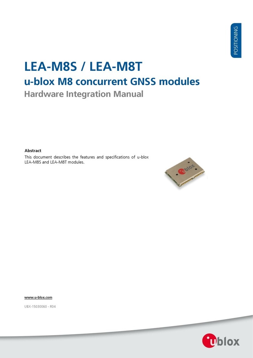
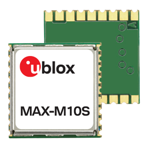
Ublox LEA-M8F Quick setup guide

LEA-M8F
u-blox M8 time and frequency reference
GNSS module
Hardware Integration Manual
Abstract
This document describes the hardware features and design-
in
aspects for the LEA-M8F time and frequency reference module. This
device incorporates the u-blox M8 concurrent GNSS IC
that can
receive GPS, GLONASS, BeiDou and QZSS signals.
It provides a low
phase noise 30.72MHz system reference oscillator disciplined by
GNSS, a precise and jitter-free time-
pulse and features high
sensitivity signal acquisition and single satelli
te timing with
automatic hold over during signal outage.
www.u
-blox.com
UBX
-14000034 - R03

LEA-M8F - Hardware Integration Manual
UBX-14000034 - R03 Early Production Information Page 2 of 30
Document Information
Title LEA-M8F
Subtitle u-blox M8 time and frequency reference GNSS module
Document type Hardware Integration Manual
Document number UBX-14000034
Revision and Date R03 19-Aug-2014
Document status Early Production Information
Document status explanation
Objective Specification Document contains target values. Revised and supplementary data will be published later.
Advance Information Document contains data based on early testing. Revised and supplementary data will be published later.
Early Production Information Document contains data from product verification. Revised and supplementary data may be published later.
Production Information Document contains the final product specification.
This document applies to the following products:
Product name Type number ROM/FLASH version PCN reference
LEA-M8F LEA-M8F-0-00 FLASH FW2.20 FTS1.01 N/A
u-blox reserves all rights to this document and the information contained herein. Products, names, logos and designs described herein may in
whole or in part be subject to intellectual property rights. Reproduction, use, modification or disclosure to third parties of this document or
any part thereof without the express permission of u-blox is strictly prohibited.
The information contained herein is provided “as is” and u-blox assumes no liability for the use of the information. No warranty, either
express or implied, is given, including but not limited, with respect to the accuracy, correctness, reliability and fitness for a particular purpose
of the information. This document may be revised by u-blox at any time. For most recent documents, visit www.u-blox.com.
Copyright © 2014, u-blox AG.
u-blox®is a registered trademark of u-blox Holding AG in the EU and other countries. ARM®is the registered trademark of ARM Limited in
the EU and other countries.

LEA-M8F - Hardware Integration Manual
UBX-14000034 - R03 Early Production Information Contents
Page 3 of 30
Contents
Contents..............................................................................................................................3
1Hardware description ..................................................................................................5
1.1 Overview .............................................................................................................................................. 5
1.2 Architecture.......................................................................................................................................... 6
1.3 Pin description for LEA-M8F designs ..................................................................................................... 7
1.4 Connecting power................................................................................................................................ 8
1.4.1 VCC .............................................................................................................................................. 8
1.4.2 V_BCKP......................................................................................................................................... 8
1.4.3 VCC_RF......................................................................................................................................... 8
1.5 Interfaces.............................................................................................................................................. 8
1.5.1 UART............................................................................................................................................. 8
1.5.2 USB ............................................................................................................................................... 8
1.5.3 Display Data Channel (DDC) .......................................................................................................... 9
1.5.4 SPI................................................................................................................................................. 9
1.5.5 DDC interface for External DAC Control...................................................................................... 10
1.6 I/O and Control Pins............................................................................................................................ 10
1.6.1 RESET_N...................................................................................................................................... 10
1.6.2 D_SEL.......................................................................................................................................... 10
1.6.3 FREQ_PHASE_IN0 / EXINT0, FREQ_PHASE_IN1 / EXTINT1............................................................. 11
1.6.4 REF_FREQ_OUT ........................................................................................................................... 11
1.6.5 TIMEPULSE / TP2 ......................................................................................................................... 11
1.7 Device Configuration.......................................................................................................................... 11
2Design .........................................................................................................................12
2.1 Layout: Footprint and paste mask ....................................................................................................... 12
2.1.1 Placement ................................................................................................................................... 12
2.1.2 Antenna connection and ground plane design ............................................................................ 13
2.1.3 Antenna micro strip connection................................................................................................... 15
2.2 GNSS Antenna Connection................................................................................................................. 16
2.2.1Passive Antenna Connection ....................................................................................................... 16
2.2.2 Active antenna connection .......................................................................................................... 17
3Migration to u-blox M8 modules ..............................................................................18
3.1 Software migration............................................................................................................................. 18
3.2 Hardware migration LEA-6T -> LEA-M8F ............................................................................................ 18
Supply Voltage .................................................................................................................19
4Product handling ........................................................................................................20
4.1 Packaging, shipping, storage and moisture preconditioning ............................................................... 20
4.2 Soldering ............................................................................................................................................ 20

LEA-M8F - Hardware Integration Manual
UBX-14000034 - R03 Early Production Information Contents
Page 4 of 30
4.3 EOS/ESD/EMI precautions ................................................................................................................... 23
4.4 Applications with cellular modules...................................................................................................... 26
Appendix ..........................................................................................................................28
Recommended parts...................................................................................................................................... 28
Manufacturer....................................................................................................................28
Order No. ..........................................................................................................................28
Comments.........................................................................................................................28
Related documents...........................................................................................................29
Revision history................................................................................................................29
Contact..............................................................................................................................30

LEA-M8F - Hardware Integration Manual
UBX-14000034 - R03 Early Production Information Hardware description
Page 5 of 30
1Hardware description
1.1 Overview
The u-blox LEA-M8F module is a standalone GNSS time and frequency reference product featuring the high
performance u-blox M8 positioning engine. The device provides multi-GNSS synchronization for cost-sensitive
network edge equipment including Small Cell and Femto wireless base-stations. The LEA-M8F module is a fully
self-contained phase and frequency reference based on GNSS, but can also be used as part of a complete timing
sub-system including macro-sniff (network listen), Synchronous Ethernet and packet timing.
The LEA-M8F module includes a low-noise 30.72 MHz VCTCXO meeting the master reference requirements for
LTE Small Cells and providing 100 ppb autonomous hold-over. An external TCXO or OCXO can also be
measured and controlled for TD-LTE, LTE-Advanced and other applications requiring extended hold-over.
External sources of synchronization are supported through time-pulse and frequency inputs and a message
interface. This allows measurements from macro-sniff, Synchronous Ethernet or packet timing to be combined
with measurements from GNSS.
The industry standard LEA form factor in the leadless chip carrier (LCC) package makes the LEA-M8F easy to
integrate, while combining exceptional timing and frequency performance with highly flexible design and
connectivity options. SMT pads allow fully automated assembly with standard pick & place and reflow-soldering
equipment for cost-efficient, high-volume production enabling short time-to-market.
For product features see the LEA-M8F Data Sheet [1].
To determine which u-blox product best meets your needs, see the product selector tables on the u-blox
website www.u-blox.com.

LEA-M8F - Hardware Integration Manual
UBX-14000034 - R03 Early Production Information Hardware description
Page 6 of 30
1.2 Architecture
Figure 1 shows a block schematic view of the module’s internal organization.
Figure 1: LEA-M8F Block Diagram
The device contains all the elements required to implement a multi-GNSS frequency and time synchronization
system. It comprises a u-blox M8030 GNSS receiver, RF LNA/SAW filter and disciplined VCTCXO. A FLASH
memory contains the FTS firmware and provides configuration storage.

LEA-M8F - Hardware Integration Manual
UBX-14000034 - R03 Early Production Information Hardware description
Page 7 of 30
1.3 Pin description for LEA-M8F designs
Function PIN No I/O Description Remarks
Power VCC 6 I Supply Voltage Provide a clean and stable supply.
GND 7,
13-
15,
17
I Ground Assure a low impedance GND connection to all GND pins of
the module, preferably with a large ground.
V_BCKP 11 I connect to VCC. (Back-up mode not supported)
VDDUSB 24 I USB Power Supply To use the USB interface connect this pin to 3.0 – 3.6 V
derived from VBUS.
If no USB serial port used connect to GND.
Antenna RF_INPUT 16 I GPS/GLONASS/
BeiDou/signal input
from antenna
Use a controlled impedance transmission line of 50 Ωto
connect to RF_IN.
Don’t supply DC through this pin. Use V_ANT pin to supply
power.
VCC_RF 18 O Output Voltage RF
section
Can be used to power an external active antenna
Ω
). The max
power consumption of the Antenna must not exceed the
datasheet specification of the module.
Leave open if not used.
V_ANT 19 I Antenna Bias voltage Connect to GND (or leave open) if Passive Antenna is used. If
an active Antenna is used, add a 10 Ωresistor in front of
V_ANT input to the Antenna Bias Voltage or VCC_RF
Reserved 20 I Leave open
UART TxD1/MISO/
TX ready
3 O Serial Port 1 or SPI
Data i/p
Communication interface o/p function dependent on D_SEL. It
can also can be programmed as TX ready for DDC interface.
Leave open if not used.
RxD1/MOSI 4 I Serial Port 1 or SPI
Data o/p
Communication interface i/p dependent on D_SEL with
internal pull-up resistor to VCC. Leave open if not used. Don’t
use external pull up resistor.
USB USB_DM 25 I/O USB I/O line USB2.0 bidirectional communication pin. Leave open if
unused. For example implementations see section 1.5.2
USB_DP 26 I/O USB I/O line
System RESET_N 10 I Hardware Reset
(Active Low)
Leave open if not used.
TIMEPULSE/TP2/
SAFEBOOT_N
28 I/O Timepulse Signal Configurable Timepulse signal (one pulse per second by
default). Leave open if not used.
FREQ_PHASE_IN0/
EXTINT0
27 I TimePulse/Frequency General purpose frequency/phase measurement input 0,
Alternate function: External Interrupt 0
FREQ_PHASE_IN1/
EXTINT1
21 I TimePulse/Frequency General purpose frequency/phase measurement input 1
Alternate function: External Interrupt 1
REF_FREQ_OUT 9 I VCTCXO o/p Buffered output from the disciplined internal 30.72MHz
VCTCXO
SDA
/CS_N
1
I/O
DDC Data Pin
or SPI chip sel.
DDC Data. Leave open if not used.
or SPI chip select: dependent on DSEL
SCL
/SCLK
2 I/O DDC Clk Pin
or SPI clk
DDC Clock. Leave open if not used.
or SPI clock: dependent on DSEL
SAFEBOOT_N 12 I Test-point for service access. Leave open, do not drive low.
D_SEL 5 Selects the
interface protocol
Used to select UART+DDC or SPI
Open = UART+DDC; low = SPI on pins 1,2,3,4
SDA_DAC 22 I/O DDC Data pin For DAC control of external Freq Reference Only
SCL_DAC 23 O DDC Clk pin For DAC control of external Freq Reference Only
Table 1: LEA-M8F Pinout

LEA-M8F - Hardware Integration Manual
UBX-14000034 - R03 Early Production Information Hardware description
Page 8 of 30
1.4 Connecting power
The u-blox LEA-M8F module has three power supply pins: VCC, V_BCKP and VDD_USB.
1.4.1 VCC
The VCC pin provides the main supply voltage. During operation, the current drawn by the module can vary by
some orders of magnitude. For this reason, it is important that the supply circuitry be able to support the peak
power for a short time. For specification see the LEA-M8F Data Sheet [1].
Use a proper GND concept with preferably low ESR decoupling capacitors at the module supply input.
Do not use any resistors or coils in the power line.
1.4.2 V_BCKP
This pin must be connected to the main module supply VCC.
1.4.3 VCC_RF
The VCC_RF pin provides a filtered source of DC to power an active antenna or external LNA. For more
information, see section 2.2.
1.5 Interfaces
The following interfaces are available for communication with a host for control and data handling.
1.5.1 UART
The LEA-M8F module includes a Universal Asynchronous Receiver Transmitter (UART) serial interface RxD/TxD
supporting configurable baud rates. See the LEA-M8F Data Sheet [1] for the supported baud rates.
The signal input and output levels are 0 V to VCC with inverted logic. An interface based on RS232 standard
levels (+/- 12 V) can be implemented using level shifters such as a Maxim MAX3232.
The interface does not support hardware handshake signals or synchronous operation.
Designs must allow access to the UART and the SAFEBOOT_N pin for future service, updates and
reconfiguration.
1.5.2 USB
A USB 2.0 (Full Speed, 12 Mb/s) compatible interface is available for communication as a development option.
The module is not designed to use the USB interface in an operational sense as the message latency cannot be
guaranteed.
The USB_DP pin has a pull-up resistor to signal a full-speed device to the USB host. The VDD_USB pin requires
connection to a 3 V (nom.) source to enable the USB interface. If the USB interface is not used, connect
VDD_USB to GND.
u-blox provides Microsoft® certified USB drivers for Windows XP, Windows Vista, Windows 7 and Windows 8
operating systems. These drivers are available for down-load at our website: www.u-blox.com
The USB port is for non-operational use e.g. for evaluation or firmware down-load

LEA-M8F - Hardware Integration Manual
UBX-14000034 - R03 Early Production Information Hardware description
Page 9 of 30
1.5.2.1 USB external components
The USB interface requires some external components to comply with the USB 2.0 specification. These are
shown below in Figure 2 and listed in Table 2. To comply with USB specifications, VBUS must be connected
through an LDO (U1) to pin 24 (VDD_USB) to regulate the 5 V VBUS down to a nominal 3.3 V for the module.
The LEA-M8F module USB interface is intended to be used as a USB self-powered device deriving its power
supply from VCC. However, the module power supply (VCC) can be turned off independently of the host VBUS
supplying VDD_USB. With VDD_USB active, the USB host would receive a signal indicating that the device is
present and ready to communicate. This should be avoided by disabling the LDO (U1) using the enable signal
(EN) of the VCC-LDO enabled by e.g. VCC. Depending on the characteristics of the LDO (U1) it is recommended
to add a pull-down resistor (R11) at its output to ensure VDD_USB is not floating if the LDO (U1) is disabled or
the USB cable is disconnected i.e. VBUS is not supplied.
Module
VDD_USB
LDO
VDD_USB
R4
USB_DP
USB_DM
R5
C24 C23
D2
VBUS
DP
DM
GND
USB Device Connector
U1
EN R11
EN
Figure 2: USB Interface
Name Component Function Comments
U1 LDO Regulates VBUS (4.4 …5.25 V)
down to a voltage of 3.3 V.
Almost no current requirement (~1 mA) if the GNSS receiver is operated as a
USB self-powered device.
C23,
C24
Capacitors Required according to the specification of LDO U1
D2 Protection
diodes
Protect circuit from overvoltage
/ ESD when connecting.
Use low capacitance ESD protection such as ST Microelectronics USBLC6-2.
R4, R5 Serial
termination
resistors
Establish a full-speed driver
impedance of 28…44 Ω
A value of 27 Ωis recommended.
R11 Resistor 100 kΩis recommended for USB self-powered setup. For bus-powered setup,
R11 can be ignored.
Table 2: Summary of USB external components
1.5.3 Display Data Channel (DDC)
An I2C compatible Display Data Channel (DDC) interface is available for serial communication with an external
host CPU. The interface only supports slave mode operation (master mode is not supported). The DDC protocol
and electrical interface are fully compatible with the Fast-Mode of the I2C industry standard. The DDC pins SDA
and SCL have internal 10 kΩpull-up resistors.
For more information about the DDC implementation, see the u-blox M8 Receiver Description Including Protocol
Specification [2]. For bandwidth information, see the LEA-M8F Data Sheet [1]. For timing, parameters consult the
I2C-bus specification [8].
The u-blox M8 DDC interface supports serial communication with u-blox cellular modules. See the
specification of the applicable cellular module to confirm compatibility.
1.5.4 SPI
An SPI interface is available for communication to a host CPU, however its interface connections are shared with
the UART and DDC interface pins.The SPI interface is not available in the default configuration but can be

LEA-M8F - Hardware Integration Manual
UBX-14000034 - R03 Early Production Information Hardware description
Page 10 of 30
enabled by connecting pin 5 (D_SEL) to ground - see 1.6.2 below. For speed and clock frequency specifications,
see the LEA-M8F Data Sheet [1].
1.5.5 DDC interface for External DAC Control
A dedicated DDC (I2C) interface (pins SDA_DAC, SCL_DAC) is provided for implementations in which the LEA-
M8F controls an external voltage controlled frequency reference via a DAC. This is set up via FTS specific
configuration messages. See the u-blox M8 Receiver Description Protocol Specification [2] and the u-blox M8F
Applications Guide [3] for more information. The DDC pins SDA_DAC and SCL_DAC have internal 10 kΩpull-
up resistors.
When the LEA-M8F is configured to discipline a voltage controlled oscillator via the dedicated DDC interface
(SDA_DAC, SCL_DAC) a choice must be made with respect to the DAC component. The recommended types
(TI or Microchip) offer 16 or 12 bit resolution respectively and should be chosen for the desired performance/cost
requirements. This section shows a suggested circuitry for implementing a 16 bit TI DAC analog filter
combination connected to a VCTCXO/VCOCXO. Note that 12 bit DAC may not provide sufficient resolution if
used over the full circuit voltage range and hence may compromise the controlled frequency performance.
Implementing a circuit using a smaller DAC voltage range and adding the output to a fixed low noise offset
voltage would be beneficial.
Figure 3: 16 bit DAC connection for VCOCXO control
1.6 I/O and Control Pins
1.6.1 RESET_N
RESET_N is an input-only pin with an internal pull-up resistor. The LEA-M8F performs an automatic reset
function on application of the power supply but this input may also be used to re-start the device during
operation if necessary. The pin must be held low for at least 10 ms to ensure RESET_N is detected. Leave
RESET_N open for normal operation. The RESET_N input complies with the power supply VCC voltage level and
can be actively driven high. Use this pin only to reset the module. Do not use RESET_N to turn the module on
and off since the reset state increases power consumption.
1.6.2 D_SEL
The D_SEL pin selects the available communication interfaces available at the module pins. This allows a choice
between UART+DDC or SPI control of the module, see Table 3 below. If D_SEL is left open both UART and DDC
are available. If pulled low, a single SPI interface is available. See the LEA-M8F Data Sheet [1].

LEA-M8F - Hardware Integration Manual
UBX-14000034 - R03 Early Production Information Hardware description
Page 11 of 30
PIN PIN 5 (D_SEL) = “high” (left open) PIN 5 (D_SEL) = “Low” (connected to GND)
1 DDC SDA SPI CS
2 DDC SCL SPI CLK
3 UART TX SPI MISO
4 UART RX SPI MOSI
Table 3: D_SEL pin configuration
1.6.3 FREQ_PHASE_IN0 / EXINT0, FREQ_PHASE_IN1 / EXTINT1
These two frequency/phase inputs are provided for connecting an external source of phase (pulse stream) or
frequency reference into the module. The pulse stream can be derived from a frequency reference or external
synchronization source. The module will measure and report the phase or frequency offset of this input with
respect to the current synchronization source and optionally steer the related oscillator to bring the externally
derived pulses into alignment.
NB. These two pins have an alternate legacy function as external interrupts and are also called EXTINT0,EXTINT1
for compatibility with standard u-blox M8 functionality.
1.6.4 REF_FREQ_OUT
This pin carries a low phase noise buffered output from the module’s disciplined 30.72MHz VCTCXO (CMOS
buffer via on-module resistor).
1.6.5 TIMEPULSE / TP2
The timepulse signal is output from this pin. This pin is the standard u-blox M8 TP2 output, hence all timepulse
settings must be made with respect to TP2 in UBX control messages.
The timepulse output pin also functions as the SAFEBOOT_N input pin at start up, initiating a special Safe Boot
Mode operation from ROM if held LO during reset (for example for Flash firmware recovery). As a result,
applications using the timepulse output should ensure that this pin is not held LO during start-up in normal
operation. This can be achieved safely by re-buffering the timepulse output using the VDD_IO supply. This pin
has an internal pull-up resistor of nominally 11 kΩ.
1.7 Device Configuration
The device configuration can be modified using UBX protocol configuration messages. Configuration settings
for the FTS functionality are explored further in the accompanying Application Guide [3]. All modified settings
remain effective until power-down or reset. The configuration can be saved permanently in SQI flash using the
UBX-CFG-CFG message. For a full explanation of all configuration messages, refer to the u-blox M8 Receiver
Description Protocol Specification [2].

LEA-M8F - Hardware Integration Manual
UBX-14000034 - R03 Early Production Information Design
Page 12 of 30
2Design
2.1 Layout: Footprint and paste mask
This section describes the footprint and provides recommendations for the paste mask for the u-blox M8F LCC
module.
These are recommendations only and not specifications. Note that the copper and solder masks have the same
size and position.
To improve the wetting of the half vias, reduce the amount of solder paste under the module and increase the
volume outside of the module by defining the dimensions of the paste mask to form a T-shape (or equivalent)
extending beyond the copper mask. For the stencil thickness, see section 4.2.
Consider the paste mask outline when defining the minimal distance to the next component. The exact
geometry, distances, stencil thicknesses and solder paste volumes must be adapted to the specific
production processes (e.g. soldering) of the customer.
17.0 mm [669 mil]
22.4 mm [881.9 mil]
1.0 mm
[39 mil]
0.8 mm
[31.5 mil]
2.45 mm
[96.5 mil]
1.1 mm
[43 mil]
3.0 mm
[118 mil]
2.15 mm
[84.5 mil]
0.8 mm
[31.5 mil]
Stencil: 150
µ
m
15.7 mm [618 mil]
17.0 mm [669 mil]
20.8 mm [819 mil]
0.8 mm
[31.5 mil]
0.6 mm
[23.5 mil]
Figure 4: LEA-M8F footprint Figure 5: LEA-M8F paste mask
2.1.1 Placement
A very important factor in achieving maximum performance is the placement of the receiver on the PCB. The
connection to the antenna must be as short as possible to avoid jamming into the very sensitive RF section.
Make sure that RF critical circuits are clearly separated from any other digital circuits on the system board. To
achieve this, position the receiver digital part towards your digital section of the system PCB. Care must also be
exercised with placing the receiver in proximity to circuitry that can emit heat. The RF part of the receiver is very
sensitive to temperature and sudden changes can have an adverse impact on performance.
The RF part of the receiver is a temperature sensitive component. Avoid high temperature drift
and air vents near the receiver.

LEA-M8F - Hardware Integration Manual
UBX-14000034 - R03 Early Production Information Design
Page 13 of 30
Non 'emitting'
circuits
PCB
Digital & Analog circuits
Non
'emitting'
circuits
Antenna
Digital Part
RF Part
1
2
3
4
5
6
7
8
9
10
11
12
13
14
28
27
26
25
24
23
22
21
20
19
18
17
16
15
RF & heat
'emitting'
circuits
PCB
Digital & Analog circuits
RF& heat
'emitting'
circuits
Antenna
1
2
3
4
5
6
7
8
9
10
11
12
13
14
28
27
26
25
24
23
22
21
20
19
18
17
16
15
Figure 6: Placement (for exact pin orientation see LEA-M8F Data Sheet [1])
2.1.2 Antenna connection and ground plane design
The LEA-M8F module can be connected to passive patch or active antennas. The RF connection is on the PCB
and connects the RF_IN pin with the antenna feed point or the signal pin of the connector, respectively. Figure 7
illustrates connection to a typical five-pin RF connector. One can see the improved shielding for digital lines as
discussed in the GPS Antenna Application Note [5]. Depending on the actual size of the ground area, additional
vias should be placed in the outer region. In particular, the edges of the ground area should be terminated with
a dense line of vias.
Figure 7: Recommended layout (for exact pin orientation see the LEA-M8F data sheet [1])

LEA-M8F - Hardware Integration Manual
UBX-14000034 - R03 Early Production Information Design
Page 14 of 30
As seen in Figure 7,an isolated ground area is created around and below the RF connection. This part of the
circuit MUST be kept as far from potential noise sources as possible. Make certain that no signal lines cross, and
that no signal trace vias appear at the PCB surface within the area of the red rectangle. The ground plane should
also be free of digital supply return currents in this area. On a multi layer board, the whole layer stack below the
RF connection should be kept free of digital lines. This is because even solid ground planes provide only limited
isolation.
The impedance of the antenna connection has to match the 50 Ωimpedance of the receiver. To achieve an
impedance of 50 Ω, the width W of the micro strip has to be chosen depending on the dielectric thickness H,
the dielectric constant εrof the dielectric material of the PCB, and on the build-up of the PCB (see section 2.1.3).
Figure 8 shows two different builds: A 2-layer PCB and a 4-layer PCB. The reference ground plane is on layer 2 in
both designs. Therefore, the effective thickness of the dielectric is different.
Module
micro strip line
Ground plane
Module
micro strip line
Ground plane
PCB
PCB
Either don't use these layers or fill with ground planes
H
H
Figure 8: PCB build-up for micro strip line. Left: 2-layer PCB, right: 4-layer PCB
General design recommendations:
•The length of the micro strip line should be kept as short as possible. Lengths over 2.5 cm (1 inch) should be
avoided on standard PCB material and without additional shielding.
•For multi-layer boards, the distance between micro strip line and ground area on the top layer should at
least be as large as the dielectric thickness.
•Routing the RF connection close to digital sections of the design should be avoided.
•To reduce signal reflections, sharp angles in the routing of the micro strip line should be avoided. Chamfers
or fillets are preferred for rectangular routing; 45-degree routing is preferred over Manhattan style
90-degree routing.
Antenna
Antenna
Antenna
PCB
PCB PCB
1
2
3
4
5
6
7
8
9
10
11
12
13
14
28
27
26
25
24
23
22
21
20
19
18
17
16
15
1
2
3
4
5
6
7
8
9
10
11
12
13
14
28
27
26
25
24
23
22
21
20
19
18
17
16
15
1
2
3
4
5
6
7
8
9
10
11
12
13
14
28
27
26
25
24
23
22
21
20
19
18
17
16
15
Wrong better best
Figure 9: Recommended micro strip routing to RF pin (for exact pin orientation see LEA-M8F Data Sheet [1])
•Do not route the RF-connection underneath the receiver. The distance of the micro strip line to the ground
plane on the bottom side of the receiver is very small (some 100 µm) and has huge tolerances (up to 100%).
Therefore, the impedance of this part of the trace cannot be controlled.
•Use as many vias as possible to connect the ground planes.

LEA-M8F - Hardware Integration Manual
UBX-14000034 - R03 Early Production Information Design
Page 15 of 30
•In order to avoid reliability hazards, the area on the PCB under the receiver should be entirely covered with
solder mask. Vias should not be open. Do not route under the receiver.
2.1.3 Antenna micro strip connection
There are many ways to design wave-guides on printed circuit boards. Common to all is that calculation of the
electrical parameters is not straightforward. Freeware tools like AppCAD from Avago Technologies or TXLine
from Applied Wave Research, Inc. are of great help. They can be downloaded from
http://www.avagotech.com/pages/appcad or http://www.hp.woodshot.com/ and www.mwoffice.com.
The micro strip is the most common RF interconnect configuration for printed circuit boards. The basic
configuration is shown in Figure 10 and Figure 11. As a rule of thumb, for an FR-4 material the width of the
conductor is roughly double the thickness of the dielectric to achieve 50 Ωline impedance.
For the correct calculation of the micro strip impedance, not only must one consider the distance between the
top and the first inner layer, but also the distance between the micro strip and the adjacent GND plane on the
same layer.
Use the Coplanar Waveguide model for the calculation of the micro strip dimensions.
Figure 10: Micro strip on a 2-layer board (Agilent AppCAD Coplanar Waveguide)
Figure 10 shows an example of a 2-layer FR4 board with 1.6 mm thickness and a 35 µm (1 ounce) copper
cladding. The thickness of the micro strip is comprised of the cladding (35 µm) plus the plated copper (typically
25 µm). Figure 11 is an example of a multi layer FR4 board with 18 µm (½ ounce) cladding and 180 µ dielectric
between layer 1 and 2.

LEA-M8F - Hardware Integration Manual
UBX-14000034 - R03 Early Production Information Design
Page 16 of 30
Figure 11: Micro strip on a multi layer board (Agilent AppCAD Coplanar Waveguide)
2.2 GNSS Antenna Connection
2.2.1 Passive Antenna Connection
A design using a passive antenna requires more attention to the layout of the RF section. Typically, a passive
antenna is located near electronic components; therefore take care to reduce electrical noise that may interfere
with the antenna performance. Passive antennas do not require a DC bias voltage and can be directly connected
to the RF input pin, RF_IN. Sometimes, they may also need a passive matching network to match the impedance
to 50 Ω.
Figure 12 shows a minimal setup for a design with a good GNSS patch antenna.
Figure 12: Module design with passive antenna (for exact pin orientation see the LEA-M8F Data Sheet[1])
Use an antenna that has sufficient bandwidth to receive all GNSS constellations. See the recommended
types in the Appendix.

LEA-M8F - Hardware Integration Manual
UBX-14000034 - R03 Early Production Information Design
Page 17 of 30
2.2.2 Active antenna connection
Active antennas have an integrated low-noise amplifier. Typically, they require an additional 5 to 20 mA that
will contribute to the total GNSS system power consumption.
If the supply voltage of the u-blox M8 receiver matches the supply voltage range of the antenna (e.g. 3.0 V), use
the filtered supply voltage at VCC_RF to supply the antenna DC power. The V_ANT pin provides a current
limited supply connection to the RF_IN pin for antenna LNA biasing, see Figure 13 below.
Figure 13: Active antenna design, external supply from VCC_RF (for exact pin orientation see LEA-M8F Data Sheet [1])
For powering an active antenna with an alternative voltage to the module VCC, use an external supply as shown
in Figure 14.
Figure 14: Active antenna design, direct external supply (for exact pin orientation see the LEA-M8F Data Sheet [1])
When the VCC_RF voltage does not match with the antenna supply voltage, use a filtered external
supply as shown in Figure 14.

LEA-M8F - Hardware Integration Manual
UBX-14000034 - R03 Early Production Information Migration to u-blox M8 modules
Page 18 of 30
3Migration to u-blox M8 modules
u-blox is committed to ensuring that products in the same form factor are backwards compatible over several
technology generations. Utmost care has been taken to minimize impact on function and performance and to
make u-blox M8 modules as compatible as possible with earlier modules.
Make sure that the RF path (antenna and filtering parameters) matches that of the GNSS constellations used.
To use BeiDou, review the bandwidth of the external RF components and the antenna. For information about
power consumption, see the LEA-M8F Data Sheet [1].
It is highly advisable that customers consider a design review with the u-blox support team to ensure the
compatibility of key functionalities.
3.1 Software migration
For an overall description of the module software operation, see the u-blox M8 Receiver Description
including Protocol Specification [2]
For software migration details, see the u-blox 7 to u-blox M8 Software Migration Guide [4].
3.2 Hardware migration LEA-6T -> LEA-M8F
This section compares the functionality when a design is migrated from a LEA-6T to a LEA-M8F. Most pins are
compatible however, the following items have changed:-
•A single timepulse (TP2) output
•USB interface not recommended for operational use
•No back-up battery operation supported
•Interface option serial/SPI selectable by D_SEL line
•No antenna supervisor(status) function
•Timepulse 2 replaced with output frequency signal REF_FREQ_OUT
The Timepulse output from LEA-M8F must be allowed to float during start-up and reset (see section 1.6.5)
Table 4 outlines the difference in pin connections between the two modules.

LEA-M8F - Hardware Integration Manual
UBX-14000034 - R03 Early Production Information Migration to u-blox M8 modules
Page 19 of 30
Pin
No.
LEA-6T LEA-M8F Remarks for Migration
Pin Name Typical Assignment Pin Name Typical Assignment
1 SDA2 DDC Pins SDA2/CS_N
DDC data or SPI chip
select
Depends on D_SEL (pin 5) status
2 SCL2
DDC Pins SCL2/SCLK
DDC clock or SPI clock
Depends on D_SEL (pin 5) status
3
TxD1
Serial Port 1
TxD1/MISO
UART TX or SPI MISO Depends on D_SEL (pin 5) status
4 RxD1 Serial Port 1 RxD1/MOSI UART RX or SPI MOSI
Depends on D_SEL (pin 5) status
5 NC Leave open DSEL Interface type
selection
Used to select UART+DDC or SPI only
Open = UART+DDC; GND = SPI on pins
1,2,3,4
6 VCC Supply Voltage VCC Supply Voltage No difference
7
GND
Ground
GND
Ground
No difference
8 VCC_OUT Leave open if not
used.
VCC_OUT Leave open if not used. No difference
9 Timepulse TimePulse2 o/p REF_FREQ_OUT VCTCXO o/p Module VCTCXO signal o/p
10 RESET_N
Hardware Reset
(Active Low)
RESET_N
Hardware Reset (Active
Low)
11 V_BCKP Backup voltage
supply
V_BCKP
Backup voltage
supply
Back-up operation not supported -
Connect to Vcc
12
SAFEBOOT_
N
GND Reserved Leave Open Test-point for service access
13
GND
GND
GND
GND
No difference
14
GND
GND
GND
GND
No difference
15 GND GND GND GND No difference
16 RF_IN RF input RF_IN RF input No difference
17 GND GND GND GND No Difference
18 VCC_RF
O/P Voltage for RF
section
VCC_RF
O/P Voltage for RF
section
No difference
19 V_ANT Ant. Bias V V_ANT Ant. Bias V No difference
20 AADET_N
Active Antenna
Detect
Reserved
Leave Unconnected
No Antenna Supervision
21 NC
No Connection
FREQ_PHASE_I
N1/ EXTINT1
2nd Freq/ PPS input
22 NC
No Connection
SDA_DAC
DDC pin for Ext DAC
o/p
.
23 NC
No Connection
SCL_DAC
DDC pin for Ext DAC
o/p
24 VDD USB USB Voltage
Source VDD USB USB Voltage Source Not supported for operational use
25 USB_DM USB I/O Line - USB I/O Line USB I/O Line - Not supported for operational use
26 USB_DP USB I/O Line + USB I/O Line USB I/O Line + Not supported for operational use
27 EXTINT0 Ext. Interupt FREQ_PHASE_IN
0/ EXTINT0 1st Freq/ PPS input
28 Timepulse Timepulse signal Timepulse/TP2/
SAFEBOOT_N
Timepulse signal
SAFEBOOT_N
Timepulse is TP2
Must float during reset (see 1.6.5)
Table 4: Pin-out comparison LEA-6T vs. LEA-M8F

LEA-M8F - Hardware Integration Manual
UBX-14000034 - R03 Early Production Information Product handling
Page 20 of 30
4Product handling
4.1 Packaging, shipping, storage and moisture preconditioning
For information pertaining to reels and tapes, Moisture Sensitivity levels (MSL), shipment and storage
information, as well as drying for preconditioning see the LEA-M8F Data Sheet [1].
Population of Modules
When populating the modules, make sure that the pick and place machine is aligned to the copper pins
of the module and not on the module edge.
4.2 Soldering
Soldering paste
Use of "No Clean" soldering paste is strongly recommended, as it does not require cleaning after the soldering
process has taken place. The paste listed in the example below meets these criteria.
Soldering Paste: OM338 SAC405 / Nr.143714 (Cookson Electronics)
Alloy specification: Sn 95.5/ Ag 4/ Cu 0.5 (95.5% Tin/ 4% Silver/ 0.5% Copper)
Melting Temperature: 217 °C
Stencil Thickness: See section 2.1
The final choice of the soldering paste depends on the approved manufacturing procedures.
The paste-mask geometry for applying soldering paste should meet the recommendations.
The quality of the solder joints on the connectors (’half vias’) should meet the appropriate IPC
specification.
Reflow soldering
A convection type-soldering oven is highly recommended over the infrared type radiation oven.
Convection heated ovens allow precise control of the temperature, and all parts will heat up evenly, regardless
of material properties, thickness of components and surface color.
As a reference, see the "IPC-7530 Guidelines for temperature profiling for mass soldering (reflow and wave)
processes”, published in 2001.
Preheat phase
During the initial heating of component leads and balls, residual humidity will be dried out. Note that this
preheat phase will not replace prior baking procedures.
•Temperature rise rate: max. 3 °C/s. If the temperature rise is too rapid in the preheat phase it may cause
excessive slumping.
•Time: 60 - 120 s. If the preheat is insufficient, rather large solder balls tend to be generated. Conversely, if
performed excessively, fine balls and large balls will be generated in clusters.
•End Temperature: 150 - 200 °C. If the temperature is too low, non-melting tends to be caused in areas
containing large heat capacity.
Heating/ Reflow phase
The temperature rises above the liquidus temperature of 217°C. Avoid a sudden rise in temperature as the slump
of the paste could become worse.
•Limit time above 217 °C liquidus temperature: 40 - 60 s
•Peak reflow temperature: 245 °C
Table of contents
Other Ublox Receiver manuals

Ublox
Ublox EVA-M8M Quick setup guide

Ublox
Ublox NEO-D9C Use and care manual

Ublox
Ublox NEO-M9N Use and care manual

Ublox
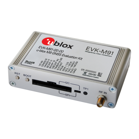
Ublox EVK-M91 User manual

Ublox
Ublox EVA-7M User manual

Ublox
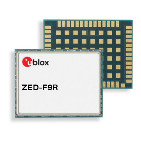
Ublox ZED-F9R Use and care manual

Ublox
Ublox EVK-F9T User manual

Ublox
Ublox EVK-7 User manual

Ublox
Ublox ZED-F9R Use and care manual

Ublox
Ublox Navilock NL-82002U User manual