UGO BASILE 37370 User manual

UGO BASILE S.R.L.
ugobasile
.com
instruction manual
Plantar Test (
Hargreaves Apparatus
)
Cat. No. 37370

UGO BASILE S.R.L.
Via Di Vittorio, 2
21036 GEMONIO, VA, ITALY
Phone: +39 0332 744574
instruction manual
Plantar Test
Cat. No. 37370
www.
ugobasile
.com
Serial No.
SAFETY CONSIDERATIONS
ALTHOUGH THIS INSTRUMENT HAS BEEN DESIGNED WITH INTERNATIONAL SAFE-
TY STANDARD, THIS MANUAL CONTAINS INFORMATION, CAUTIONS AND WARN-
INGS WHICH MUST BE FOLLOWED TO ENSURE SAFE OPERATION AND TO RETAIN
THE INSTRUMENT IN SAFE CONDITIONS.
SERVICE AND ADJUSTMENTS SHOULD BE CARRIED OUT BY QUALIFIED PERSON-
NEL, AUTHORIZED BY UGO BASILE ORGANIZATION.
ANY ADJUSTMENT, MAINTENANCE AND REPAIR OF THE OPENED INSTRUMENT UN-
DER VOLTAGE SHOULD BE AVOIDED AS MUCH AS POSSIBLE AND, WHEN INEVITA-
BLE, SHOULD BE CARRIED OUT BY A SKILLED PERSON WHO IS AWARE OF THE
HAZARD INVOLVED.
CAPACITORS INSIDE THE INSTRUMENT MAY STILL BE CHARGED EVEN IF THE IN-
STRUMENT HAS BEEN DISCONNECTED FROM ITS SOURCE OF SUPPLY.
Instruction Manual dated October 2013
Revision 0

www.ugobasile.com
Plantar Test
(Hargreaves Apparatus)
General
Determination of acute nociceptive thermal threshold in laboratory animals has primarily relied upon the tail ick and
hot plate methods.
Although both methods are used frequently in pharmacological studies, they are not without limitation. In addition,
neither method has been extended to investigating behavioural responses to hyperalgesia.
The Plantar Test represents a remarkable advance in methodology, as it combines the best features of all other methods
of measuring pain sensitivity. Unique to the Plantar Test, the animal is unrestrained and unhandled during experi-
ments.
PAIN and INFLAMMATION
For Rats
Cat. No. 37370
AUTOMATIC
MEASUREMENT OF THE
ANIMAL RESPONSE
Main Features
l Automatic detection of paw with-
drawal (no visual score needed!)
l I.R. intensity adjustable in the
interval 01-99 (in one digit steps)
l Software included
l Modular animal enclosure, from 3 to 12 spaces,
conveniently designed to restrain mice or rats
l Optional 37300 Radiometer for calibration
l Data portability via the included memory key
l NEW: orofacial stimulation by optional holders
For Mice
Ugo Basile: more than 10,000 citations

CHECK-LIST
Cat. No. 37370 Plantar Test
(Hargreaves Apparatus)
CLIENTE / CUSTOMER______________________________________________
Ordine No. / Order No. ____________________ Data / Date____/_____/______
UB code CAT.No.
Q.ty DESCRIPTION DESCRIZIONE
37370-001 1 CONTROL UNIT UNITÀ DI CONTROLLO
37370-002 1 MOVABLE I.R. SOURCE UNITÀ DI STIMOLAZIONE I.R.
37000-003 1 COMPLETE BASE BASE COMPLETA
37370-327 4 SUPPORTING COLUMNS COLONNE DI SUPPORTO
37370-005 1 FRAMED GLASS PANE PANNELLO IN VETRO CON CORNICE
3 x M-S 085 37000-006 1 MODULAR ANIMAL ENCLOSURE
(3 MODULES) GABBIA MODULARE
(3 MODULI)
E-WP 008 1 MAINS CABLE EUROPE CAVO RETE EUROPA
E-WP 008-1 USA USA
E-FF 002 2 FUSES (2AF) FUSIBILI (2AF)
E-AU 041 USB
pen-drive 37370-302 1 INSTRUCTION MANUAL MANUALE DI ISTRUZIONE
52050-10 CUB SOFTWARE SOFTWARE CUB
52010-323 1 USB CABLE CAVO USB
OPTIONAL
37000-145 1 PANEL MOUNT PRINTER STAMPANTE A PANNELLO
37400-305 1 PACKAGE OF 10 PAPER ROLLS PACCO DA 10 ROTOLI CARTA
37370-278 1 ADDITIONAL STIMULATION BASE BASE STIMOLAZIONE AGGIUNTIVA
DATE / / Serial No. IMBALLATO DA / PACKED BY
Universal Input 85-264 VAC, 50-60Hz
IMPORTANT/IMPORTANTE:
Check the shipment for completeness immediately after receipt: should you find any discrepancy, please fill in the following part and transmit it to
our fax no. +39 0332 745488
Al ricevimento della merce controllate che la spedizione sia completa: in caso di discrepanza, completate il formulario di seguito riportato ed in-
viatelo al nostro fax no. 0332 745488
FROM: Name Company/Institution
DATE REF.
NOTE
MOD.04 REV 0

Page i
37370 Instruction Manual (Rev. 0)
C O N T E N T S
1GENERAL ..........................................................................................................1
1.1PRINCIPLE OF OPERATION .....................................................................................1
2INSTRUMENT DESCRIPTION...........................................................................2
2.1THE MOVABLE I.R. SOURCE (HEAT STIMULATOR)...................................................2
2.2THE PLATFORM/GLASS-PANE/ENCLOSURE ASSEMBLY ...........................................2
2.2.1ANIMAL ENCLOSURE 3
2.3CONTROLLER .......................................................................................................3
2.3.1COMMAND DISPLAY MODULE 3
2.3.2GRAPHIC DISPLAY 4
2.3.3KEYBOARD 4
2.3.4FUNCTION KEY ABBREVIATIONS 4
3DATA ACQUISITION & DATA PRINT-OUT ......................................................5
3.1DATA PORTABILITY ...............................................................................................5
3.2PANEL-MOUNT PRINTER 37000-145......................................................................6
3.357145 MINIPRINTER .............................................................................................6
4INSTALLATION .................................................................................................6
4.1UNPACKING &PRELIMINARY CHECK ......................................................................6
4.2NOTES ON THE INSTRUCTION MANUAL ....................................................................7
4.3ASSEMBLING THE EQUIPMENT................................................................................7
4.3.1ASSEMBLING &POSITIONING THE ENCLOSURE 7
4.3.2HOW TO HANDLE THE PLANTAR TEST 7
4.4ENVIRONMENT ......................................................................................................8
4.5BEFORE APPLYING POWER....................................................................................8
4.5.1FUSE HOLDER 8
4.5.2MAIN SWITCH 8
4.5.3MAINS CORD 9
4.6CONNECTIONS ......................................................................................................9
4.6.1BACK PANEL 9
4.7INSTALLATION OF CUB SOFTWARE ......................................................................10
4.8INTENDED USE ....................................................................................................10
4.9GENERAL SAFETY INSTRUCTIONS.........................................................................10
4.10ADDITIONAL SAFETY CONSIDERATION ..................................................................10
5OPERATION ....................................................................................................11
5.1SWITCHING ON...................................................................................................11
5.2DISPLAY CONTRAST ............................................................................................11
5.3SETTING I.R. INTENSITY.......................................................................................11
5.4CARRYING OUT THE TEST ON THE ANIMAL.............................................................12
5.4.1NOTE ON WET SURFACES 12
5.5DURHAM HOLDERS FOR OROFACIAL STIMULATION ................................................12

Page ii
37370 Instruction Manual (Rev. 0)
5.6HOW TO SET A CUSTOMIZED EXPERIMENTAL CONFIGURATION............................... 12
5.6.1SEQUENCE NUMBER 13
5.6.2EXPERIMENT NUMBER 14
5.6.3ANIMAL GENDER 14
5.6.4CUT-OFF TIME 14
5.7CONFIGURATION FILE ......................................................................................... 14
5.7.1FROM THE MEMORY KEY TO THE INSTRUMENT 15
5.7.2UPLOADING 15
5.7.3DOWNLOADING 16
5.7.4FROM MEMORY KEY TO PC 16
5.7.5FROM PC TO INSTRUMENT 16
6OPERATING WITH MINI PRINTER AND PC.................................................. 16
6.1HOW TO SET THE DATA OUTPUT TO PC ................................................................ 16
6.2HOW TO SET THE DATA OUTPUT TO MINIPRINTER.................................................. 16
6.3DATUM FORMAT ................................................................................................. 17
6.4QUICK SETTING OF THE 37370 PLANTAR TEST ..................................................... 18
7MEMORY MANAGEMENT .............................................................................. 19
7.1MEMORY RESET ................................................................................................. 20
7.1.1“MEMORY FULL”MESSAGE 20
7.2SETTING TIME &DATE ........................................................................................ 21
8REPRODUCIBILITY OF THE TEST ................................................................ 21
9CALIBRATION ................................................................................................ 21
9.1RADIOMETER...................................................................................................... 22
9.2CALIBRATION VIA THE 37300 I.R. RADIOMETER.................................................... 22
9.3CALIBRATION WITHOUT I.R. RADIOMETER ............................................................ 23
10MAINTENANCE............................................................................................... 23
10.1ELECTRICAL....................................................................................................... 24
10.1.1BATTERY REPLACEMENT 24
10.2REPLACING THE BULB ........................................................................................ 25
10.3CLEANING THE OPTICS THOROUGHLY .................................................................. 25
10.4CLEANING THE GLASS PANE............................................................................... 26
10.5REPLACING THE GLASS PANE.............................................................................. 26
10.6LONG INACTIVITY................................................................................................ 26
10.7CUSTOMER SUPPORT ......................................................................................... 26
11INSTRUMENT SPECIFICATIONS................................................................... 27
12ORDERING INFORMATION............................................................................ 28

12.1SPARE PARTS .....................................................................................................28
12.2OPTIONAL ..........................................................................................................28
12.3THERMAL MINIPRINTER .......................................................................................29
13BIBLIOGRAPHY ..............................................................................................29
13.1METHOD PAPER..................................................................................................29
13.2PAPERS MENTIONING UGO BASILE PLANTAR TEST ...............................................29
13.3DURHAM HOLDERS FOR OROFACIAL STIMULATION ................................................30
14APPENDIX .........................................................................................................1
FIGURE INDEX
Figure 1 “I.R. Source”......................................................................................................................2
Figure 2 “Panel-Mount Printer and USB Pen-Drive” .......................................................................6
Figure 3 “Power Module”.................................................................................................................8
Figure 4 “Back Panel”......................................................................................................................9
Figure 5 “Acquired Data Window”.................................................................................................17

Page 1
37370 Instruction Manual (Rev. 0)
Plantar Test (Hargreaves Apparatus)
Cat. 3 7 3 7 0
1 GENERAL
The Hargreaves’ Method (see paragraph 12-BIBLIOGRAPHY) enables the researcher
to discern a peripherally mediated response to thermal stimulation caused by drugs in the
unrestrained rat.
The Basile Plantar Test has been designed to perform this high sensitivity in-vivo test on
the experimental animal under optimum conditions.
The Plantar Test represents a remarkable advance in methodology, as it combines the
best features of all other methods of measuring pain sensitivity:
it allows bilateral testing, like the Randall-Selitto (paw pressure) method.
the behavioral end point is detected automatically, as with the Tail Flick method.
it stimulates the glabrous normal skin of the foot, as opposed to the unique tissue
of the tail, as does the Hot Plate method.
repeated testing does not result in sensitization, an advantage shared only with
the Tail Flick method.
orofacial stimulation, by optional holders, see paragraph 5.5.
Unique to the Plantar Test, the animal is unrestrained and unhandled during experi-
ments, which enables other more subjective measures of behaviour to be recorded.
These measures, unavailable with any other method of analgesia testing, provide addi-
tional information about the effect of the drug and the state of the animal.
1.1 Principle of Operation
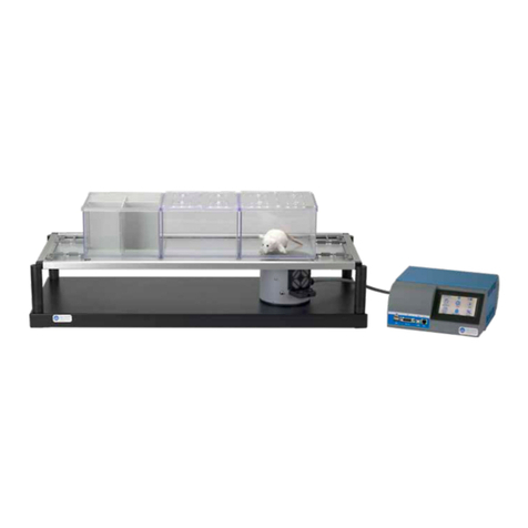
The Plantar Test basically consists of a movable I.R. (infrared) generator placed below a
glass pane upon which the operator deposits the rat, see picture. A Perspex enclosure
defines the space within which the animal is unrestrained. It is divided in three compart-
ments, which help the operator to carry out a rapid “screening” work: up to 12 animals
can be tested with no appreciable delay in between.
After the acclimation period, the I.R. source placed under the glass floor (see the picture)
is positioned by the operator directly beneath the hind paw. A trial is commenced by de-
pressing a key, positioned on the stimulating unit. An additional start key is located on the
front panel of the Controller.

Page 2
37370 Instruction Manual (Rev. 0)
When the rat feels pain and withdraws its paw, the I.R. source switches off and the reac-
tion time counter stops. The withdrawal latency to the nearest 0.1s is automatically de-
termined.
2 INSTRUMENT DESCRIPTION
The Instrument consists of:
1) a movable I.R. Source, see paragraph 2.1
2) a Platform/Glass-Pane/Animal-Enclosure Assembly, see paragraph 2.2
3) a Controller lodged in a cabinet of original design, incorporating a Co-
mand/Display Module, see paragraph 2.3.
2.1 The Movable I.R. Source (Heat Stimulator)
The I.R. Source 37370-002 is lodged into a cy-
lindrical vessel of aluminum, fitted with a side
handle, which the operator glides over the sur-
face of the base platform (see figure 1).
At both sides of the handle (1), a START key is
provided, to help both left (2) and right (3)
handed operators.
The cylinder contains a halogen bulb coupled to
an I.R. filter, which cuts off the visible part of the
spectrum. The bulb is cooled by a quietly oper-
ating fan.
When the rat feels pain and withdraws its paw,
a suitable electronic circuitry switches off the
bulb and to stop the second counter, thus de-
termining the withdrawal latency to the nearest
0.1 second.
Figure 1 “I.R. Source”
2.2 The Platform/Glass-Pane/Enclosure Assembly
The I.R. Vessel glides on the large base platform 37000-003. The Glass Pane 37370-
005 is inserted into a consistent frame, whose external dimensions are 86(w)x35(d)cm,
held in position by its own weight on the top of the four supporting columns 37370-327,
fitted to the platform.
3 2
1

Page 3
37370 Instruction Manual (Rev. 0)
2.2.1 Animal Enclosure
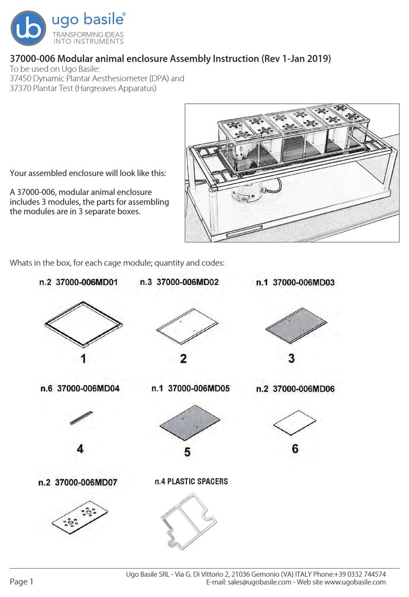
A modular enclosure 37000-006 of
original design, combines 3 animal
cages.
Removable partitions enable the us-
er to divide each of the 3 cages into
2 or 4 spaces, thus obtaining up to
12 spaces.
The enclosure is duly held in position
on the framed glass pane, by the
spacers provided.
Six separate lids make it easier to de-
posit/remove the rats individually.
The cage dimensions are approx.
20(d)x62(w)x14(h)cm.
Each of the 3 compartment is hence
dimensioned 20x20x14(h)cm.
2.3 Controller
The controller front panel encompasses the COMMAND-DISPLAY MODULE, see para-
graph 2.3.1 and the slot for the memory key, see paragraph 3.1-Data Portability.
The back panel, see paragraph 4.6.1, embodies the power module and the connection
module, see also paragraph 4.6.
2.3.1 Command Display Module
This module of original design is located on the instrument front panel, and comprises a
graphic display and a command keyboard.
The multifunction liquid-crystal graphic-display monitors the withdrawal latency to the
nearest 0.1 second; latency time is the time elapsing from the moment the START key is
activated to the moment the animal withdraws its paw.
Removable
partitions
Separate
Lids

Page 4
37370 Instruction Manual (Rev. 0)
The graphic display presents all available commands: the operator sets the experiment
configuration via the command keyboard located on the right of the display.
2.3.2 Graphic Display
When the instrument is switched on, our
logo with the two mice is displayed.
By depressing F4 (ESC), you enter the user
area.
The four lines of the top area show:
1) the actual date
2) the actual time
3) the instrument serial number
4) the firmware version
In all menus, the last two lines show the functions available by depressing the corre-
sponding key on the right of the display.
The right portion of the display window
shows the abbreviation of the key function,
meaning:
OPR Operation
FNC Function
MEM Memory
ESC Escape
The display contrast can be modified, see paragraph 5.2-Display Contrast.
2.3.3 Keyboard
The keyboard, consisting of 4 soft push-button keys F1, F2, F3 and F4, sets the experi-
ment parameters, see paragraph 2.3.4 for reference.
2.3.4 Function Key Abbreviations
CAL Calibration
CFG Configuration
CLK Clock setting
CUT Cut-off time
DIS Display contrast
DWN Decrement
ENT Enter
EPR External printer
ESC Escape
FNC Function menu
FTR Feature menu
The F4 key, which has the
function of ESCAPE key, en-
ables the operator to leave a
menu and go back to a pre-
viousl
y
selected one.

Page 5
37370 Instruction Manual (Rev. 0)
MEM Memory menu
MPR MiniPrinter
MSK Memory stick
NO No
NUL Annulment
OK Confirm
OPR Operation menu
OUT Out
PRN Data printing selection
RES Data memory reset
STR Start
STP Stop
UP Increment
V.W Data view
YES Yes
> Shift to right
3 DATA ACQUISITION & DATA PRINT-OUT
The Plantar Test is a microprocessor controlled unit. The experimental data, stored in the
37370 internal memory and shown on its graphic display, can be directly exported to PC.
The USB connector type B connects directly into the PC USB port. This connector is lo-
cated on the instrument back panel (see paragraph 4.6.1). The connection to PC is also
possible via the serial port RS 232 C by the Delta 9-pin female connector (COM 1).
Communication is managed by the dedicated CUB Package Cat. 52050-10, supplied as
standard.
The CUB 52050 is a Windows® based Data Acquisition Software Package, which ena-
bles the research worker to route to the PC the data originated by all Ugo Basile instru-
ments and store them into individual files, ready to be easily managed by most statistical
analysis packages available on the market. See also paragraph 4.7.
Ask for details!
3.1 Data Portability
Data portability is arranged via the USB pen-drive (E-AU 041) provided with the stand-
ard package. Via the USB slot provided on the front panel, all the experimental data of
one or more sessions can be easily uploaded on the pen-drive, see B, Figure 2, in para-
graph 3.2
Programming the experiment layouts from a remote PC is also made easy by the use of
the pen-drive.

Page 6
37370 Instruction Manual (Rev. 0)
3.2 Panel-Mount Printer 37000-145
The 37370 Plantar Test
can be provided with a
panel-mount printer, Cat.
No. 37000-145, to print
the experimental data on
its 58 mm wide paper,
see Figure 2.
The printer can be or-
dered together with the
dynamic plantar aesthe-
siometer, or separately.
Its installation is extreme-
ly easy: you simply have
to replace the top panel
with a new panel incorpo-
rating the dedicated
printer.
Ask for details!
Figure 2 “Panel-Mount Printer and USB Pen-Drive”
3.3 57145 MiniPrinter
The MiniPrinter 57145 is a compact thermal printer device, supplied as an optional part,
suitable to print experimental data on 58mm wide paper, see paragraph 12.3-Thermal
MiniPrinter
See paragraph 4.6 for connection to the Plantar Test via the 10-pin cable provided with
the Mini-Printer and paragraph 6.2 to enable the data print-out on the MiniPrinter.
For further details, please refer to Mini-Printer Instruction Manual.
4 INSTALLATION
4.1 Unpacking & Preliminary Check
Check the contents of the shipment for completeness, packing list to hand, and visually
inspect the instrument as soon you take it out of the packaging. Use the supplied Check
List.
If the instrument is damaged, inform the carrier immediately, notifying our company. If af-
ter having tested it, the Plantar Test fails to meet rated performances, please contact our
after sales service, see paragraph 10.7-Customer Support.
B
A

Page 7
37370 Instruction Manual (Rev. 0)
Protect the environment!
Dispose of packaging properly, according to existing and ap-
plicable waste management rules and regulations.
4.2 Notes on the Instruction Manual
The Plantar Test Instruction Manual included in the package (on the USB pen-drive) is
necessary for the correct installation and operation of the instrument.
We recommend reading the manual with attention, as it is essential for the correct instal-
lation and operation of the instrument.
Please save the manual, ready to be consulted by the qualified personnel who use the
instrument. Print it, only if necessary.
Our Instruction Manuals are available as free download on our web, see
http://www.ugobasile.com/support/documentation.html. For any additional information
and/or assistance, you are welcome to contact our Service Department (see paragraph
10.7-Customer Support), specifying the serial number of your instrument.
4.3 Assembling the Equipment
Assemble the Plantar Test on a stable and flat bench or table surface.
Tighten the four supporting columns at the corners of the base platform, until their upper-
right-angle indentations are oriented to fit the angle blocks of the frame. The frame is
held in position by its own weight.
Lift the frame front bar 1-2 cm, to provide the clearance to insert the I.R. vessel. Make
sure the vessel glides freely over all available surface.
4.3.1 Assembling & Positioning the Enclosure
Assemble the animal enclosure, combining the 3 animal cages, as clearly indicated in the
assembly instructions included in each box. Obtain the number of spaces you need (up
to 4 per each cage), by the grey partitions provided, see also paragraph 2.2.1.
Use the four spacers provided, leaving them in place during test, to make sure the enclo-
sure is correctly positioned and held in place. This will enable the I.R. beam which comes
out from the Vessel to scan the entire enclosure floor.
4.3.2 How to Handle the Plantar Test
The Plantar Test is a relatively bulky and heavy instrument, with fragile parts, and it is
recommended that two people lift it.

Page 8
37370 Instruction Manual (Rev. 0)
Once the Plantar Test is assembled, do not attempt to lift or move the combined unit. In
particular, do not incline the base, as the framed glass may accidentally come off the
supporting columns, with the consequences you may imagine!
4.4 Environment
Avoid direct illumination of the enclosure compartments, e.g., from a
table lamp.
This will definitely upset the animals which dislike full light, not to speak of the risk to
raise their body temperature, also taking into account body heat, confined space, good
thermal insulation of Perspex and glass.
Moreover, intense light may cause the sensor to miss the paw withdrawal, as a light
source from above tends to mask the I.R. energy reflected back by the paw.
We recommend absorbing with cotton wool any occasional large emission of urine during
familiarization or test time. A plantar surface, if wet by urine, will be definitely less sensi-
tive to the thermal stimulus because of the large specific heat of any watery solution, see
also paragraph 5.4.1.
4.5 Before Applying Power
Consider the Power Module on the back side of the Control Unit, which includes (from left
to right):
the inlet connector of the
mains cord
the mains switch
the fuse holder
Figure 3 “Power Module”
4.5.1 Fuse Holder
The instrument is provided with 2 fuses, on both neutral and live. To replace fuses, if
necessary, pull out the fuse slide, see paragraph 10.1-Electrical.
It is recommended to use fast-blow fuses type F2A; make sure that only fuses with the
required rated current and of the specified types are used for replacement. The use of
repaired fuses and the short circuiting of the fuse holders must be avoided.
4.5.2 Main Switch
This two-pole toggle switch, which complies with international safety standards, provides
a visual cue, to signal the:
- OFF position by O
- ON position by I

Page 9
37370 Instruction Manual (Rev. 0)
4.5.3 Mains Cord
It is a standard cable, Cat. # E-WP008, see paragraph 12-ORDERING INFORMATION.
Make sure your power outtake is provided with a reliable ground connection.
4.6 Connections
Connect the mains cord to a power outtake, provided with a reliable earth connection,
protected by a differential earth-leakage switch (CGFI) that breaks at the threshold of
0.03A, within a max. acceptable delay of 1s. The maximum breaking compliance required
by the CGFI is 10kA at rated current is 6A.
4.6.1 Back Panel
Beside the mains module, the back panel embodies a connection module, see figure be-
low.
Figure 4 “Back Panel”
The connection module encompasses, from left to right:
USB this USB type B connector for linking the Plantar Test to the USB port of the
PC
COM1 a delta 9-pin female connector for connection to the serial port RS232C of the
PC
COM2 a second delta 9-pin connector (male) for connection to an external serial
printer
MINI
PRINTER a 20-pin connector to the Mini Printer Cat. 57145, see also (see paragraphs
3.3 and 12.3
TO I.R.
EMITTER a 7-pin circular connector to link the I.R. Emitter. This cable connector features
a push-pull latch. Pull out the knurled ring to remove the connector.
Mismatching the connection is prevented by the different individual pin arrangement.

Page 10
37370 Instruction Manual (Rev. 0)
4.7 Installation of CUB software
The CUB software is contained in the USB pen-drive provided with the instrument. Install
it on your PC.
At the first installation, a code will be generated: send the code to registra-
From the installation, you have 30 days to enter the activation key; when the 30 days trial
period expires, it will not be possible to activate the software and it will be necessary to
uninstall and install it again (ask for instruction at our Customer Support, see paragraph
10.7).
4.8 Intended Use
The Plantar Test is intended for investigation use on laboratory animals only.
4.9 General Safety Instructions
The following guidelines must be followed to ensure safe operation.
DO NOT attempt to open or perform any service work
DO NOT connect up human subjects
4.10 Additional Safety Consideration
a. Place your Plantar Test on a flat surface;
b. Pay attention when handling the glass-pane; in case of breakage, use heavy
duty gloves to handle the glass pieces and chips;
c. Do not obstruct free and comfortable access to the power module;
d. Use original accessories and spare parts only, see also paragraph 12-
ORDERING INFORMATION
e. Immediately disconnect and replace a damaged mains cable;
f. Do not operate the instrument in hazardous environments or outside pre-
scribed environmental limitations (i.e. +18C°/+24C°, 60% relative humidity,
non-condensing);
g. Do not spray any liquid on the connectors;
h. Keep inflammables far from the heating source.
UGO BASILE DOES NOT ACCEPT ANY RESPONSIBILITY FOR PROBLEMS OR
HARM CAUSED TO THINGS OR PERSONS, ARISING FROM:
incorrect electrical supply;
incorrect installation procedure;

Page 11
37370 Instruction Manual (Rev. 0)
incorrect or improper use or, in any case, not in accordance with the purpose
for which the instrument has been designed and the warnings stated in the in-
struction manual supplied with the instrument;
replacement of original components, accessories or parts with others not ap-
proved by the manufacturer;
servicing carried out by unauthorized personnel
5 OPERATION
5.1 Switching On
Switch on the 37370; the software takes some seconds to perform a complete checking
of the electronic circuit. During the checking, the display shows the mice logo. By de-
pressing ESC, the display shows the software version which is actually installed, e.g.,
“V1.0”, see paragraph 2.3.2.
The software version is necessary in case of communication with our laboratory for oper-
ational or servicing problems.
In case one of the captions MEMORY LOSS!! appears on the display, please refer to para-
graph 10.1.1-Battery Replacement.
5.2 Display Contrast
To modify the display contrast, depress the F2 (FNC) key from the Main Menu, then the
F3 (DIS) key. The display shows:
Keep the arrow keys F1 (UP ) or F2 (DWN)
depressed until you reach the desired dis-
play contrast.
The readability of the liquid crystal display
depends on the angle of view: select the
ideal contrast according to the height of the
table, the operator’s distance and so on.
5.3 Setting I.R. Intensity
Before carrying out the test on the animal,
set the I.R. intensity. Enter the I.R. setting
menu, by depressing F1 (OPR), F2 (SET)
and F1 (IR ).
The following display will appear:
Now use the F1 (UP ) or F2 (DWN) keys to set intensity to the desired value.

Page 12
37370 Instruction Manual (Rev. 0)
5.4 Carrying out the Test on the Animal
After the acclimation period, the I.R. source placed under the glass floor (see picture) is
positioned by the operator directly beneath the hind paw. A trial is commenced by de-
pressing the START key on either side of the vessel, or F1 (STR) on the front panel.
When the rat feels pain and withdraws its paw, the I.R. source switches off and the reac-
tion time counter stops. The withdrawal latency to the nearest 0.1 s is automatically de-
termined.
The datum shown on the display can be printed on the Mini-Printer or routed to the PC,
see paragraph 6-OPERATING WITH MINI PRINTER AND PC.
5.4.1 Note on Wet Surfaces
We recommend absorbing with cotton wool any occasional large emission of urine during
familiarization or test time. A plantar surface, if wet by urine, will be definitely less sensi-
tive to the thermal stimulus because of the large specific heat of any watery solution.
Be patient and dry the glass pane before the first test and at least between each test.
5.5 Durham Holders for Orofacial Stimulation
The Durham Animal Holders are the newest accessory for use with the Plantar Test and
Dynamic Plantar Aesthesiometer, manufactured by Ugo Basile.
These animal holders extend the
scope of the infrared (IR) thermal
stimulus of the Plantar Test to tri-
geminal stimulation. In fact, this
new invention allows the applica-
tion of the same stimulus to the
region innervated by the trigemi-
nal nerve.
The 37100 includes two holders,
form-moulded for testing specific
size ranges; the two sizes have
been optimized for young adult
rats and for bigger rats.
See ordering information, paragraph 12.2-Optional and bibliography, paragraph 13.3.
5.6 How to Set a Customized Experimental Configuration
This function enables the operator to personalize the basic datum by adding, in se-
quence:
sequence number (see 5.6.1)

Page 13
37370 Instruction Manual (Rev. 0)
experiment number (see 5.6.2)
animal gender (see 5.6.3)
From the main menu, depress the F2 (FNC) key, followed by the F1 (OUT) key. Depress
again the key F2 (FTR); the display shows the first setting, the sequence number.
All the available selections for each additional information are displayed in a loop. Scan
them by the F1 (UP ) or F2 (DWN) keys, select the suitable one and confirm the selection
by depressing the F4 (OK) key, or avoid one or more features by depressing the F3
(NUL) key.
The selected features will be maintained even if the instrument is turned off.
To erase one or more features previously set, simply enter this software level, highlight
the concerned feature and depress the F3 (NUL) key.
After entering the last feature (M or F), the software goes automatically back to the main
menu.
5.6.1 Sequence Number
The first additional information to be de-
fined is the sequence number. This section
is highlighted as soon as the F2 (FTR) key
is depressed.
Use the F1 (UP ) or F2 (DWN) key to set
the desired sequence number from 01 to
99 and confirm it by depressing the F4
(OK) key.
The sequence number will automatically increase by one figure at any subsequent
measurement. It trips once a datum has been acquired and recorded, indicating the fresh
sequence number ready for the next measurement.
If a sequence number is not necessary, depress the F3 (NUL) key.
IMPORTANT:
When a fresh experimental session is begun, the sequence number can be
carried on from the number reached at the end of the previous trial or a new
number can be entered, following the instructions outlined above, for exam-
ple starting from 01.
Table of contents
Other UGO BASILE Laboratory Equipment manuals
Popular Laboratory Equipment manuals by other brands

Tuttnauer
Tuttnauer EZ9Plus Cleaning and maintenance instructions

Miele professional
Miele professional A 306/1 operating instructions

Hermle
Hermle Z 446 user manual

JEOL
JEOL JNM-ECA Series user manual

Sartorius Stedim Biotech
Sartorius Stedim Biotech Biostat RM 200 Rocker operating manual

RR Mechatronics
RR Mechatronics Lorrca MaxSis user manual

coltene/whaledent
coltene/whaledent PINDEX owner's guide

VOLTCRAFT
VOLTCRAFT LSP-2165 operating instructions

GE
GE ImageQuant LAS 4000 Original instructions

Oxford Nanopore
Oxford Nanopore PromethION48 quick start guide

Thermo Scientific
Thermo Scientific Premium Series quick start guide

Maestrogen
Maestrogen Ultra Slim LED Illuminator instruction manual