UGO BASILE - I
TALY
Page 3
57800 Instruction Manual (Rev. 1)
1.1.1
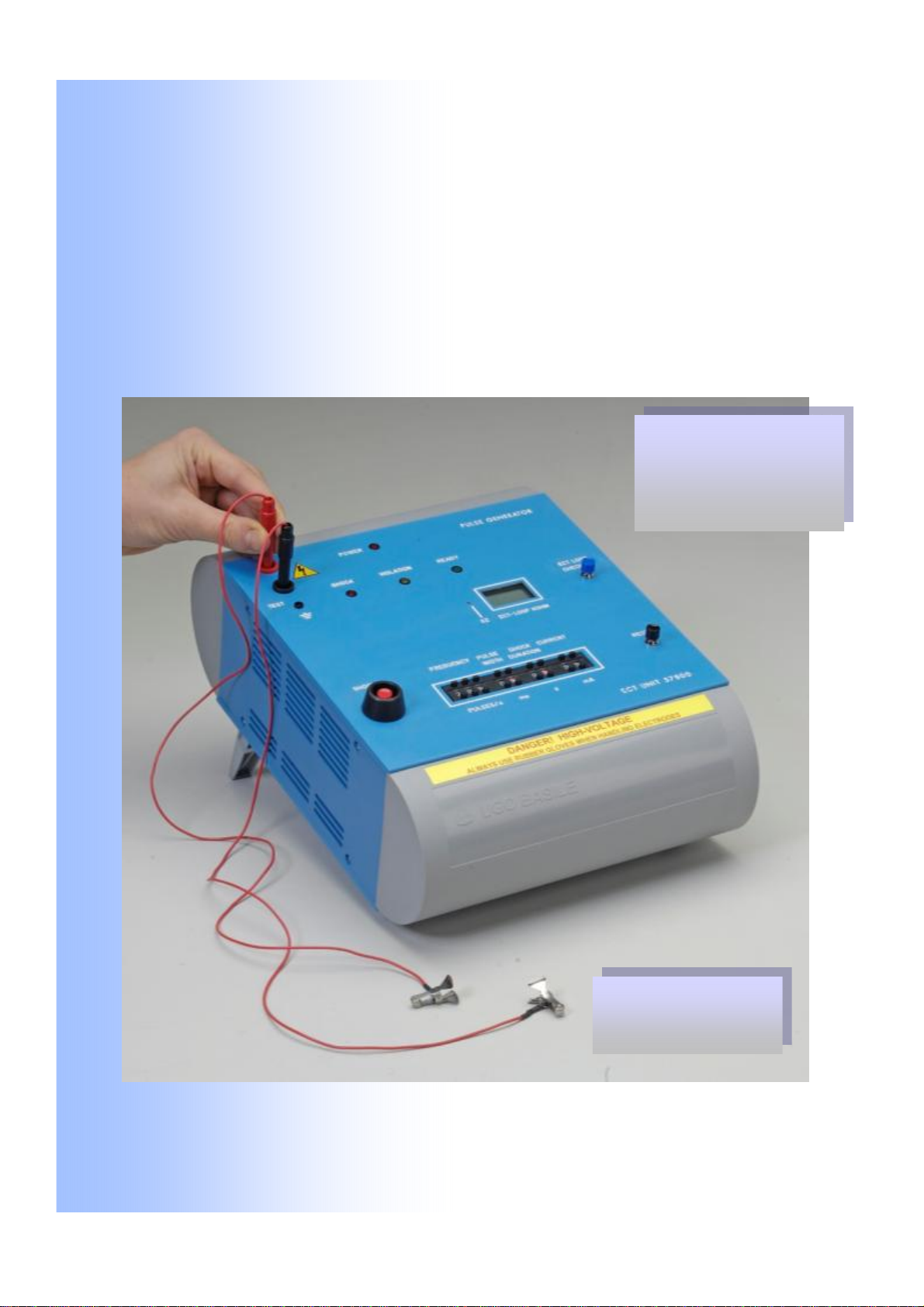
Pulse Generator
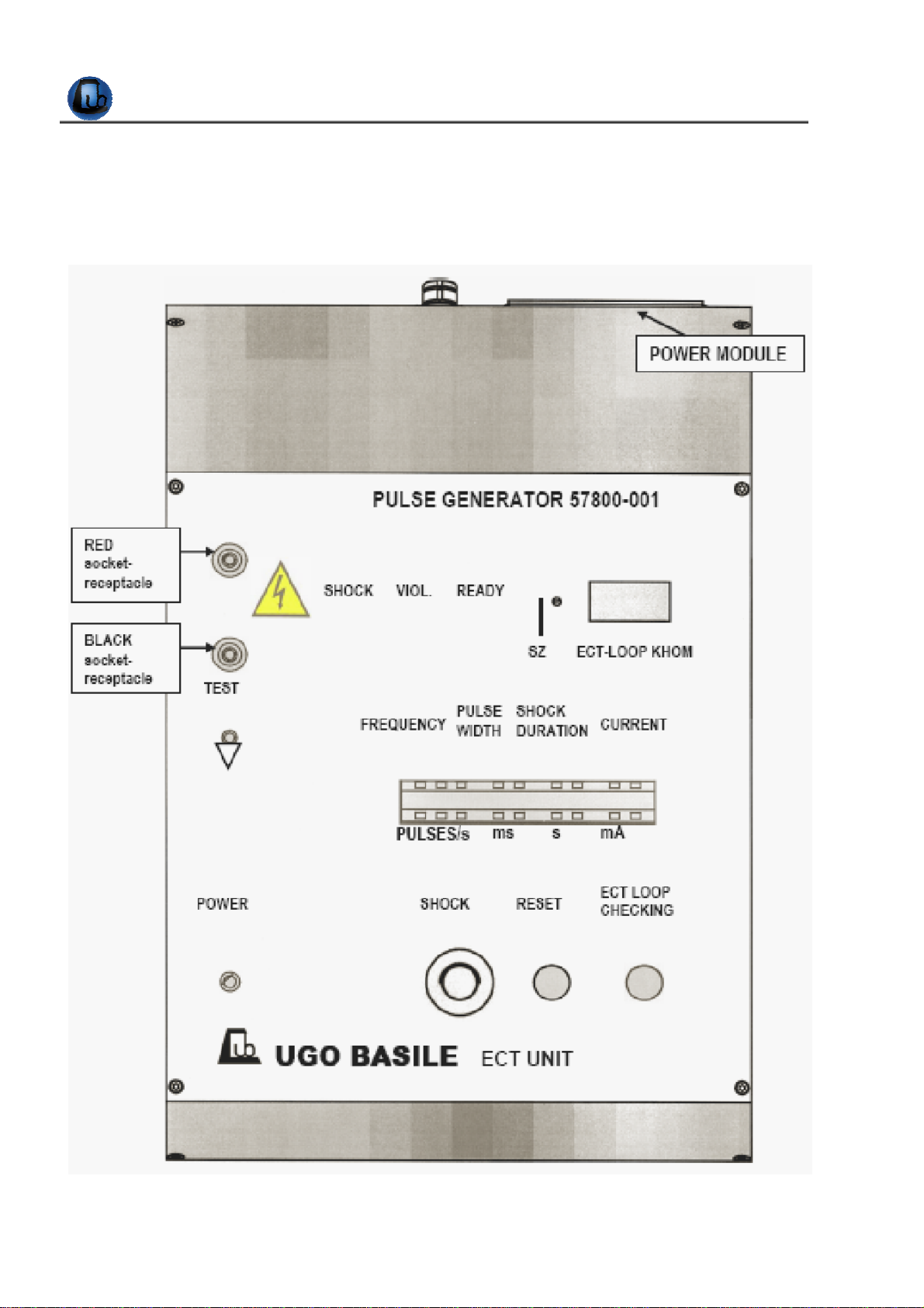
The Pulse Generator is lodged into a resilient cabinet of original design. Its upper panel,
see Figure 1 “Upper Panel”, features the following controls:-
1.1.2
Reset
When the apparatus is on, to deliver a shock, the circuit should first be reset by keeping
the RESET key depressed (for about 1 second) until the illuminated green legend
READY is ON.
This prevents inadvertent shock delivery due to accidentally depressing the shock key.
IF THE RESET AND THE SHOCK KEYS ARE ACCIDENTALLY DEPRESSED AT THE
SAME TIME, THERE IS NO OPERATION.
1.1.3
Shock
This red key causes the instrument to deliver the shock pulse train. Once the RESET
(green) LED is ON, the SHOCK key should be depressed throughout the duration of
the shock, which is monitored by the illuminated red legend.
The shock duration timer (monitored by the red LED) is in fact independent on the time
the key is depressed .
In other words, when releasing the shock key, you cut the power off.
This type of actuating arrangement operates as a safety device; even in the unlikely
event of an electronic breakdown, no shock can be delivered unless the output stage is
energized by the key in the depressed position.
1.1.4
Current Setting and “Violation”
The dual thumb-wheel “CURRENT” presets the shock current between 1 and 99 mA.
In the case the preset current cannot be delivered (for instance due to high animal im-
pedance or to disconnected electrodes), the VIOLATION legend and the “beeper” come
alive, see also paragraph 3.4-Electrode Positioning.
1.1.5
Shock Parameter Switches
These switches set the shock parameters, i.e., pulse width in ms, frequency in pulses per
second, shock duration in seconds and current in mA.
1.2 Electrodes
The ECT Unit is provided as standard with Auricular Electrodes 57800-002. Corneal
Electrodes 57800-003 are also available as optional, see paragraph 8-ORDERING IN-
FORMATION. Different types of electrodes are available on request.