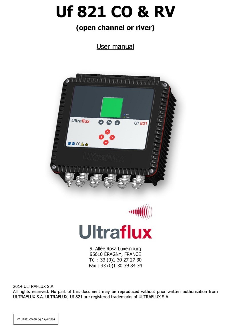
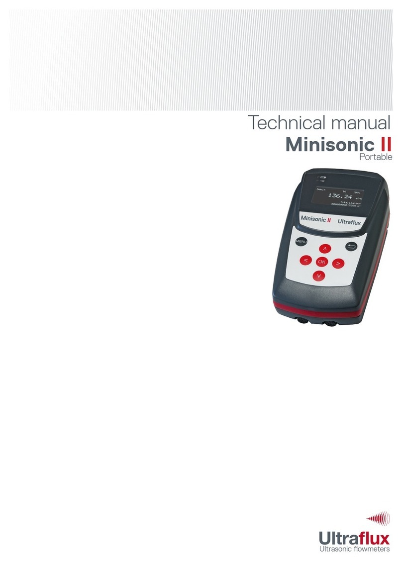
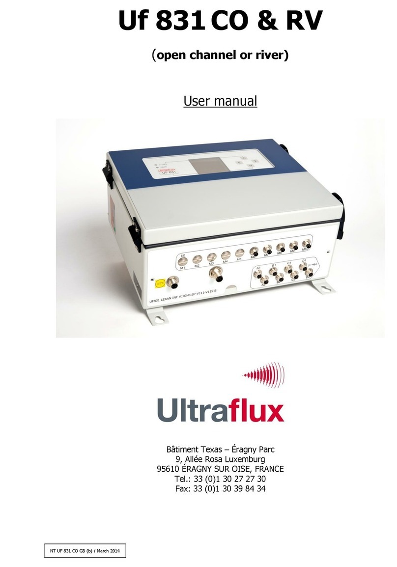
Ultraflux Uf 811 CO User manual

NT UF 811 CO GB (c) / March 2014
Uf 811 CO
(open channel)
User Manual
Bâtiment Texas –Éragny Parc
9, Allée Rosa Luxemburg
95610 ÉRAGNY SUR OISE, FRANCE
Tel.: 33 (0)1 30 27 27 30
Fax: 33 (0)1 30 39 84 34
2012 ULTRAFLUX S.A.
All rights reserved. No part of this document may be reproduced without prior written authorisation from
ULTRAFLUX S.A. ULTRAFLUX, Uf 811 are registered trademarks of ULTRAFLUX S.A.

2
NT UF 811 CO GB (c) / March 2014
TABLE OF CONTENTS
Note: A detailed table of contents is provided at the end of the manual.
Important: If you are unfamiliar with the transit time difference measuring technique, we recommend you start by
reading our training manual "Ultrasonic transit time flowmeter".
CHAPTER 1: OVERVIEW___________________________________________4
1.1 Converter overview _____________________________________________________________ 5
1.2 Dimensions and weight __________________________________________________________ 5
1.3 Working environment____________________________________________________________ 5
1.4 Protection against dust and immersion ______________________________________________ 5
1.5 Power supply __________________________________________________________________ 6
1.6 Communication ________________________________________________________________ 6
1.7 Inputs/Outputs_________________________________________________________________ 7
1.8 Ultrasound chords ______________________________________________________________ 7
1.9 Navigation keys ________________________________________________________________ 7
1.10 Operating lamps_______________________________________________________________ 8
1.11 Screen ______________________________________________________________________ 8
1.12 Functions ____________________________________________________________________ 9
1.13 Performance of the flow meter ___________________________________________________ 9
1.14 Cleaning the flow meter_________________________________________________________ 9
1.15 Recycling the flow meter ________________________________________________________ 9
1.16 CE marking__________________________________________________________________ 10
CHAPTER 2: SAFETY INSTRUCTIONS________________________________11
2.1 Using the flow meter ___________________________________________________________ 12
2.2 Symbols used on the flow meter __________________________________________________ 12
2.3 Contact address _______________________________________________________________ 13
CHAPTER 3: INSTALLATION AND WIRING ___________________________14
3.1 Wall attachment_______________________________________________________________ 15
3.2 Wiring instructions _____________________________________________________________ 16
3.3 Connector wiring ______________________________________________________________ 16
3.4 Ground connection_____________________________________________________________ 27
3.5 Connection ___________________________________________________________________ 27

3
NT UF 811 CO GB (c) / March 2014
CHAPTER 4: IMPLEMENTING A MEASURING POINT ____________________28
4.1 Choosing the measurement location _______________________________________________ 29
4.2 Installing the probes ___________________________________________________________ 29
4.3 Measurements to be taken on site ________________________________________________ 30
4.4 Analysing and processing data measured on site _____________________________________ 30
4.5 Transferring the data collected to the converter______________________________________ 31
CHAPTER 5: USING AND CONFIGURING THE Uf 811 ____________________32
5.1 Using the Uf 811 ______________________________________________________________ 33
5.2 Main configuration elements _____________________________________________________ 34
5.3 Configuring the UF 811 _________________________________________________________ 37
5.4 SIMPLE configuration mode______________________________________________________ 38
5.5 NORMAL configuration mode_____________________________________________________ 56
5.6 ADVANCED configuration________________________________________________________ 59
5.7 "Measurement" mode __________________________________________________________ 62
CHAPTER 6: FUNCTION ENGINE ___________________________________65
6.1 Principle _____________________________________________________________________ 66
6.2 Application example____________________________________________________________ 66
CHAPTER 7: PC SOFTWARE _______________________________________67
7.1 Introduction __________________________________________________________________ 68
7.2 Archiving, processing and printing of saved files _____________________________________ 82
7.3 Settings files__________________________________________________________________ 82
Appendix I: Characteristic echo signals______________________________83
Appendix II: Speed of sound in water _______________________________86
Appendix III Troubleshooting _____________________________________88
III.1 Diagnostic indications _________________________________________________________ 89
III.2 Description of fault bits ________________________________________________________ 91
III.3 Fault grid ___________________________________________________________________ 94
Appendix IV: Link protocol of the Uf 811 ____________________________95
IV.1 Serial link characteristics _______________________________________________________ 96
IV.2 Reading of N words (with N ≤ 125)_______________________________________________ 97
IV.3 Modbus / Jbus table ___________________________________________________________ 98
IV.4 CRC16 calculation algorithm____________________________________________________ 102

4
NT UF 811 CO GB (c) / March 2014
CHAPTER 1: OVERVIEW

5
NT UF 811 CO GB (c) / March 2014
1.1 Converter overview
1.2 Dimensions and weight
Height: 231 mm
Width: 221 mm
Depth: 59 mm
Weight: 2 Kg
1.3 Working environment
Temperature: from -20 to +70°C
Hygrometry: 80 % maximum
Screen reading: from -20°C to +60°C
Ventilation: no special precautions necessary
1.4 Protection against dust and immersion
IP 67: Total protection against dust; protection against immersion for 30 minutes under 1m of water. This
protection is only valid if the installation has been carried out or audited by Ultraflux.
This protection is only ensured when the connectors are connected or capped (where the connector is not in
use).
Screen
USB (optional)
Operating lamps
Navigation keys
Chord 1
Chord 2
Inputs/Outputs 1
Inputs/Outputs 2
Serial communication
Ground connection
Power supply
Wall fixing holes

6
NT UF 811 CO GB (c) / March 2014
1.5 Power supply
Range: 10–32 VDC (SELV networks)
Insulation: Safety class 3
Peak power consumption: < 12 W
Average typical consumption: < 6 W
Protection via resettable fuse (PTC)
Protection against polarity reversal
Overvoltage protection in accordance with standard EN 61000-4-5
Notes:
As the device is supplied from a protected extra low voltage network, an earth connection is not
mandatory. Nevertheless, it is strongly recommended to install an earth connection in order to
protect the installation, particularly when used outside with a long length of cable connected to the
device. The earth can be connected to the power socket or via one screw.
It is recommended to install a disconnectable bipolar circuit breaker interrupter with visible cut-off
of 2 A upstream of the flow meter power supply. It is also recommended to install lightning
arresters on each of the inputs/outputs of the flow meter.
Important:
The connectors must only be connected or disconnected with the power off and the equipment
isolated.
If the flow meter unit is opened by anyone other than an Ultraflux technician, the warranty will be
rendered null and void.
Ultraflux accepts no responsibility for incidents which may occur following a failure to respect these
instructions.
1.6 Communication
The Uf 811 has a serial link which can be wired using RS232 or RS485 mode. It also has a USB interface.
For this communication interface, the standard protocol chosen is the Slave JBUS (MODBUS). This enables
the device to be connected to an instrumentation and control system or to a computer. Ultraflux provides PC
software compatible with Windows XP or later which is used to configure the device, unload the logger and
display the various values measured.
Please refer to the appendices for the JBUS configuration.
Note:
If necessary, the 120 Ohm termination resistance for the RS485 may be added in the connector
between the Y and Z pins.
The USB interface allows a computer to be connected for configuration. This may be accessed by
removing the IP protective cap.

7
NT UF 811 CO GB (c) / March 2014
1.7 Inputs/Outputs
The Uf 811 provides the following options:
Integration of up to 4 single modules (or 2 double modules) of inputs/outputs.
Connection of the inputs/outputs to the equipment directly via connectors, without the need for
any intervention inside the flow meter.
The modules are factory-installed by Ultraflux.
The Uf 811 allows six types of inputs/outputs to be used:
Single module 1 active 4-20 mA insulated analogue output: current from 0 to 24 mA,
Single module 2 passive 4-20 mA insulated analogue inputs: current from 0 to 24 mA,
Single module 2 passive 0-10 V insulated analogue inputs: voltage from 0 to 15 V,
Single module 2 on/off outputs (50 V - 10 mA) which can be used as frequency outputs,
Single module 2 on/off inputs (5 V),
Double module 2 PT100/PT1000 temperature inputs; 2- 3- or 4-wire.
Notes:
Please refer to the descriptive sheet for each module for more details.
The sensors on the 4-20 mA loop may by powered from an external power supply.
1.8 Ultrasound chords
The Uf 811 can manage 2 ultrasound chords. Each connector corresponds to one ultrasonic chord, in other
words two probes. As standard, it is therefore necessary to use the Y-cable provided with the flow meter in
order to separate the two probe cables.
1.9 Navigation keys
Changing from one type of screen to another is done by using the "Fn" (for Function) key. This "Fn"
key in particular is used to enter "configuration" mode. The and keys allow the user to browse
through the menus for this mode.
A long press on the Fn key, or allowing approximately 1 minute to pass without using the keypad,
returns you to "measurement" mode.
Within a menu, the and keys are used to change page. These keys may also have a contextual
function which in this case will be shown at the bottom of the screen page, such as that of selecting
the measurement mode screen which is displayed by default.
After powering on the Uf 811, the screen displays the page which has been selected as priority. To
choose this "default" screen, select and validate it by pressing the "B" key in measurement mode.
To scroll through the measurement screens, use the and keys.
To access the other menus, press the "Fn" key, then successively press the key, or browse using
the and keys.

8
NT UF 811 CO GB (c) / March 2014
To enter a menu, press or .
To change page, press "A" or "B".
To change a row, select it using or and change the value using or .
If no key is pressed for approximately one minute, the Uf 811 automatically returns to
"measurement" mode and to the display chosen as priority using "B".
For a given parameter, the value to be applied is defined using the (increase) and (decrease)
keys. An extended press on one of these two keys accelerates the increase or the decrease.
1.10 Operating lamps
Two LEDs are present on the front panel:
Blue measurement LED: indicates
whether or not the flow meter is
measuring.
A flashing LED indicates normal operation.
An LED which is fixed on or off indicates abnormal or
interrupted operation.
Red, orange or green
Communication LED: indicates the
status of the external communication
of the flow meter (serial link or USB).
Flashing green light for each dialog on the serial link.
Long red flashing light on each dialog error on the serial
link.
Fixed orange light when the flow calculation is in degraded
mode or when a related function is faulty.
Fixed red light when the flow calculation is faulty.
1.11 Screen
LCD: graphic (14 rows x 20 characters).
Backlighting: permanent or timed.
Screen reading: from -20°C to +60°C.

9
NT UF 811 CO GB (c) / March 2014
1.12 Functions
Recording options: The flow meter is used to record the measurement data (logger function). Up
to 30 variables can be recorded (for example: average flow, minimum flow, maximum flow, water
level). A total of 530,000 readings can be recorded. The frequency and sequencing of the
recordings can be adjusted.
Echo display: It is possible to display the measurement echo for each chord, which allows you in
particular to check the quality of the measurement and directly view the effect of certain corrective
actions (positioning and alignment of the probes, adjustment of the settings, cleaning of the
probes, etc.).
Four flow volume totalizers which can count the positive flows, negative flows or total flows,
regardless of their sign,
Filtering of the measurement using a first-order filter allowing the non-significant flow
fluctuations to be smoothed,
Storage of the measurement in memory in the event of a momentary loss of the echo (due, for
example, to the passing of air bubbles) or other faults (adjustable storage interval),
Setting the measurement to zero if the flow is below a programmable value,
Readjustment of the zero if it is possible to completely stop the flow.
1.13 Performance of the flow meter
Uncertainty over measured speed: up to ±0.5 %.
Repeatability: up to 0.1 %.
Linearity: up to 0.1 %.
Typical uncertainty on the flow rate calculation: from 0.5 to 5 % depending on the application and
the number of chords.
Important: The accuracy of the measurement also depends on the accuracy with which the geometry of
the measuring point is measured, the dimensions of the probe pairs, the distance between the probes and
the length the wave has to travel between two probes. An inaccuracy on one of these values may
compromise the accuracy of the measurement.
1.14 Cleaning the flow meter
The box may be cleaned with water, diluted alcohol or detergent using a sponge or a soft cloth. Do not use
abrasive materials or solvents.
1.15 Recycling the flow meter
In the context of decree no. 2005-829 dated 20 July 2005 relating to the collection, treatment and disposal
of electrical and electronic equipment in France, Ultraflux delegates the responsibility for financial and also
logistical recovery to the user, who will manage their own waste.
10
NT UF 811 CO GB (c) / March 2014
1.16 CE marking
The Uf 811 complies with CE certifications:
EN 55016-2-1
Measurement of conducted emissions Criterion A
EN 55016-2-3
Measurement of radiated emissions from 30 MHz –6 GHz
EN 61000-4-6
Immunity to induced conducted disturbances Criterion B
EN 61000-4-2
Immunity to electrostatic discharges Criterion B
EN 61000-4-3
Immunity to radiated electromagnetic fields Criterion A
EN 61000-4-4
Immunity to rapid transients in bursts Criterion B
EN 61000-4-5
Immunity to shock waves Criterion B
EN 62311
Human exposure to electromagnetic fields

11
NT UF 811 CO GB (c) / March 2014
CHAPTER 2: SAFETY INSTRUCTIONS

12
NT UF 811 CO GB (c) / March 2014
2.1 Using the flow meter
The flow meter, equipped with ultrasonic measuring probes, is used to measure the flow of a liquid in an
open channel.
It is important to correctly configure the flow meter for its measurement results to be correct. You are
recommended to call on qualified staff from Ultraflux to ensure this is the case. This is strongly advised if
your equipment is used to regulate a process, intervene in a monitoring system, or in the case of other
applications for which an incorrect flow measurement would lead to risks.
In normal operation, the flow meter must not heat up to a level liable to cause burns. It is not necessary to
take any particular precautions to allow it to cool. Should the temperature of the unit rise abnormally, it is
recommended to power off the flow meter and call Ultraflux for expert advice. In the event of a fire inside
the flow meter, power it off without opening or touching it, then call the competent services in order to
secure the premises.
The flow meter must not be used beyond the possibilities and specifications given in this manual. The flow
meter must be stored in a dry place, with the packaging provided by Ultraflux in order to protect the parts
liable to be damaged by a shock. It is recommended to wear PPEs (Personal Protective Equipment) adapted
for the handling and installation of the flow meter (safety boots, protective gloves).
The flow meter must only be modified or disassembled by Ultraflux personnel. Ultraflux accepts no
responsibility should this rule not be respected. No consumables are used for the operation of the flow
meter.
The connectors must only be connected or disconnected with the power off and the equipment isolated.
Ultraflux accepts no responsibility for incidents which may occur following a failure to respect these
instructions.
2.2 Symbols used on the flow meter
User manual must be read before use
Disconnect the flow meter and power it off before opening the unit or connecting or
disconnecting inputs and outputs.

13
NT UF 811 CO GB (c) / March 2014
2.3 Contact address
For any requests for information, please contact us at:
ULTRAFLUX
9, Allée Rosa Luxemburg
95610 ERAGNY
FRANCE
http://www.ultraflux.net
E-mail : ultraflux@ultraflux.fr
Tel.: 33 (0)1 30 27 27 30
Fax: 33 (0)1 30 39 84 34
2012 ULTRAFLUX S.A.

14
NT UF 811 CO GB (c) / March 2014
CHAPTER 3: INSTALLATION AND WIRING

15
NT UF 811 CO GB (c) / March 2014
The units do not pose any particular danger to users. It is however recommended to wear personal
protective equipment during assembly, including: gloves, safety boots, impact goggles. This equipment will
allow you to avoid any risk when installing the flow meter.
It is recommended to follow the assembly method described below in order to avoid any risk of injury.
Assembly must be carried out or inspected by Ultraflux to ensure the unit is leakproof and will operate
correctly.
Important: Avoid installing the Uf 811 close to a frequency converter. If this cannot be avoided,
interference filters must be installed. It is highly recommended to contact us if this situation arises.
It is also recommended to separate the paths of the probe cables and the power cables.
3.1 Wall attachment
Make attachment holes on a wall which is sufficiently solid. Firmly screw the flow meter to the wall so that it
does not fall (take care with cavity walls).
A clearance of 80 mm must be left around the unit to allow the connectors to be connected.
221 mm
231 mm
80 mm

16
NT UF 811 CO GB (c) / March 2014
3.2 Wiring instructions
Wiring must be carried out by a person with electrical accreditation. The flow meter must be powered off
before installing or uninstalling. The isolation devices must be locked and tagged. The wiring must respect
the diagrams provided for the power supply and for the inputs/outputs.
It is sometimes necessary to protect the inputs/outputs, the power supply and the ultrasonic chords. You are
strongly recommended to contact Ultraflux to obtain a diagnosis on this point. Ultraflux accepts no
responsibility in the event of the incorrect use of the flow meter, and in such cases, the Ultraflux guarantee
would not be valid.
3.3 Connector wiring
Preliminary comments:
If using an armoured cable, be careful with the "cutting edge" of the armour after cutting it to
strip the wire. This edge may be very sharp. It is recommended to cover the cut edge of the
armour with insulating tape to prevent any accidents.
The armour must remain outside the plugs. The shielding must pass through the connector in
order to prevent interfering signals from damaging the quality of the measurement. Remember
to allow sufficient lengths to be able to access the locations of the probes and the
inputs/outputs.
The length recommendation in the assembly diagrams must be complied with in order to ensure
good contact between wire and pin and provide leaktightness.
The recommended wire cross-sections must be complied with in order to be compatible with the
connectors.
The recommended tightening torques must be complied with in order to ensure leaktightness
and the good mechanical strength of the flow meter.
Note: All connectors are supplied with the flow meter.
Tools required:
18 mm open-ended wrenches
Combination pliers
Cutting pliers
Stripping pliers
Cutter
10-m tape
Torque wrench
4 mm flat screwdriver

17
NT UF 811 CO GB (c) / March 2014
3.3.1 Communication connector
Depending on whether the RS232 or RS485 interface has been selected, connect the RX TX or A, B pins to
ground.
Notes:
The serial link is electrically insulated.
If the UF 811 is the last device on the RS485 network, a termination resistance of 120 Ohm
must be added to the connector between pins A and B.
Only one of the two interfaces may be in operation at any one time.
The connector used is a male 5-pin M12 type connector with inverted B coding.
View of the base
The pins have the following functions:
Pin
Functions
1
RS 485 : A / RTx (-)
2
RS 485 : B / RTx (+)
3
RS 232 : Tx (Output Uf 811)
4
RS 232 : Rx (Input Uf 811)
5
GND ISO
Note: the pin number is engraved directly on the connector.

18
NT UF 811 CO GB (c) / March 2014
Recommended length to strip, tightening torque and cross-section of cable:
Cross-section of conductor
0.25 mm² … 0.75 mm²
Cross-section of AWG conductor
24 … 18
External diameter of cable
6 mm … 8 mm
Tightening torque Wrench M12
0.4 Nm
Tightening torque Screw terminals
0.2 Nm
Tightening torque Set screw
0.8 Nm … 1 Nm
Plug fitting:
a
Thread on the parts.
b
Strip the cable by 35 mm.
Strip the conductors by 4 mm.
Splay the armour and place it around the
protector ring.
Cut off the excess braiding.
Feed the wires through the box.
Fit the armour, the packing and the ring
clip.
Turn the set screw to fasten the cable in
place.
Screw down the conductor wires.
Fit the connector.
Firmly tighten the set screw.

19
NT UF 811 CO GB (c) / March 2014
3.3.2 Input/output connectors
The Uf 811 can contain up to 4 single I/O modules or 2 double I/O modules.
2 connectors (I/O 1 & I/O 2) are provided for connection. Their wiring depends on the type and location of
the modules determined when the order is placed.
The location of the modules and their types are shown on the test report supplied with the device when it is
delivered.
Locations 1 & 2 are connected to connector I/O 1.
Locations 3 & 4 are connected to connector I/O 2.
The connectors used are female 8-pin type M12 connectors with A coding.
View of the base
For the I/O 1 connector, the pins have
the following functions:
For the I/O 2 connector, the pins have
the following functions:
Pin
Function
Pin
Function
1 I/O 1
Location 2 pin 1
1 I/O 2
Location 4 pin 1
2 I/O 1
Location 2 pin 2
2 I/O 2
Location 4 pin 2
3 I/O 1
Location 2 pin 3
3 I/O 2
Location 4 pin 3
4 I/O 1
Location 2 pin 4
4 I/O 2
Location 4 pin 4
5 I/O 1
Location 1 pin 1
5 I/O 2
Location 3 pin 1
6 I/O 1
Location 1 pin 2
6 I/O 2
Location 3 pin 2
7 I/O 1
Location 1 pin 3
7 I/O 2
Location 3 pin 3
8 I/O 1
Location 1 pin 4
8 I/O 2
Location 3 pin 4

20
NT UF 811 CO GB (c) / March 2014
1) Wiring of the relay modules
The pins have the following functions:
Pin
Function
1
relay A
2
relay A
3
relay B
4
relay B
2) Wiring of the current output modules
The pins have the following functions:
Pin
Function
1
current (+)
2
current (-)
3
-
4
-
3) Wiring of the current input modules
The pins have the following functions:
Pin
Function
1
current A wire 1
2
current A wire 2
3
current B wire 1
4
current B wire 2
4) Wiring of the voltage input modules
The pins have the following functions:
Pin
Function
1
voltage A(+)
2
voltage A(-)
3
voltage B(+)
4
voltage B(-)
This manual suits for next models
1
Table of contents
Other Ultraflux Measuring Instrument manuals

Ultraflux
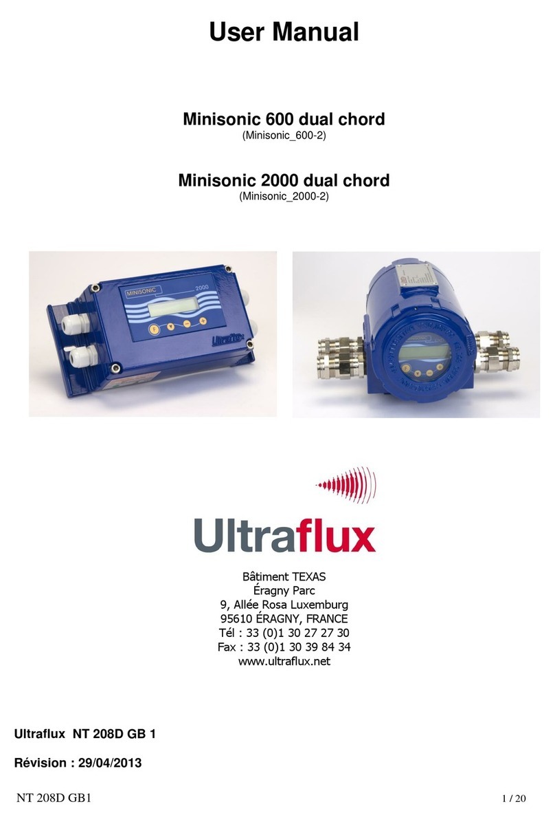
Ultraflux Minisonic Series User manual

Ultraflux
Ultraflux Uf 811 User manual

Ultraflux
Ultraflux UF 801-P User manual

Ultraflux
Ultraflux Uf 841 User manual

Ultraflux
Ultraflux Minisonic II Portable User manual

Ultraflux
Ultraflux UF 831 User manual

Ultraflux
Ultraflux Minisonic_600-2 User manual

Ultraflux
Ultraflux Uf 821 User manual

Ultraflux
Ultraflux MiniSonic P User manual

Ultraflux
Ultraflux UF 801-PB User manual