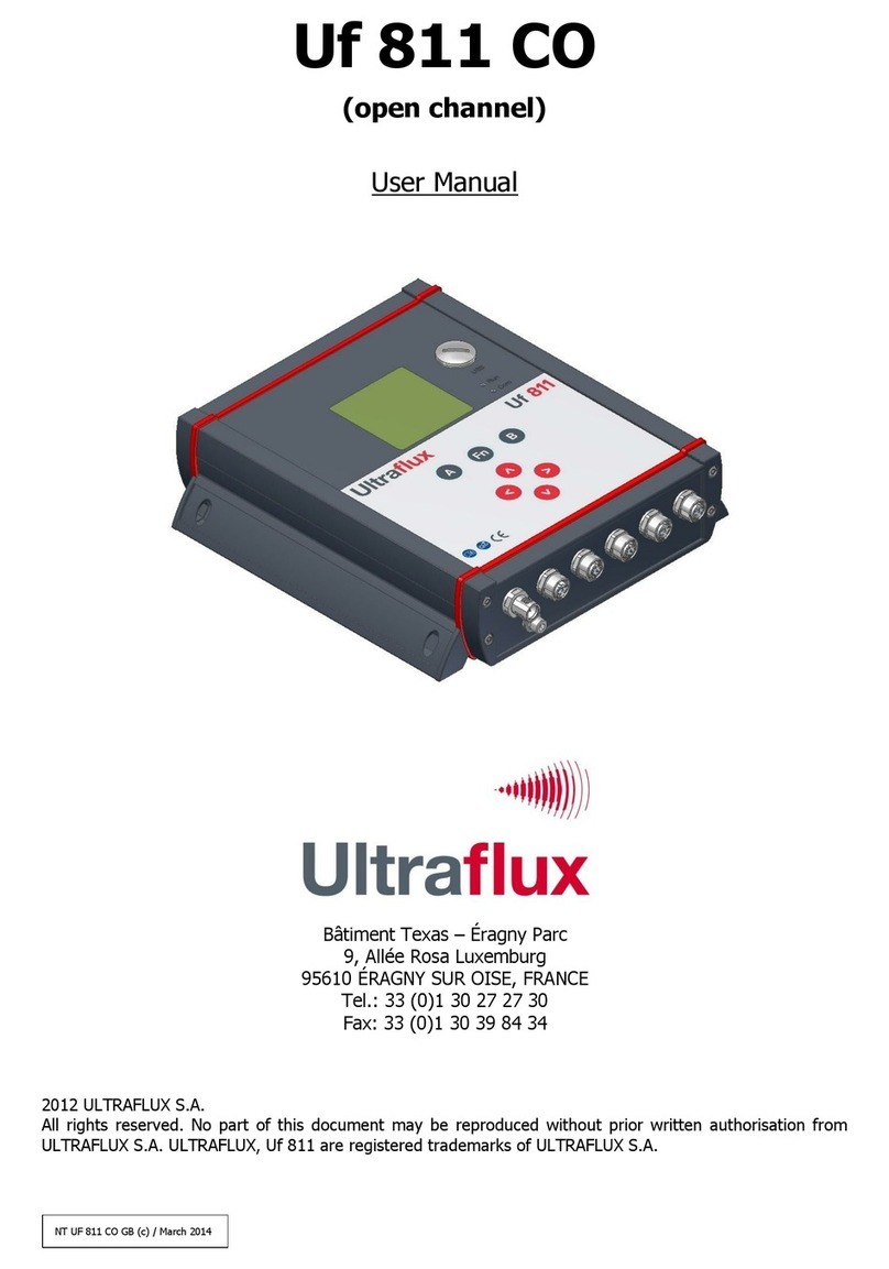
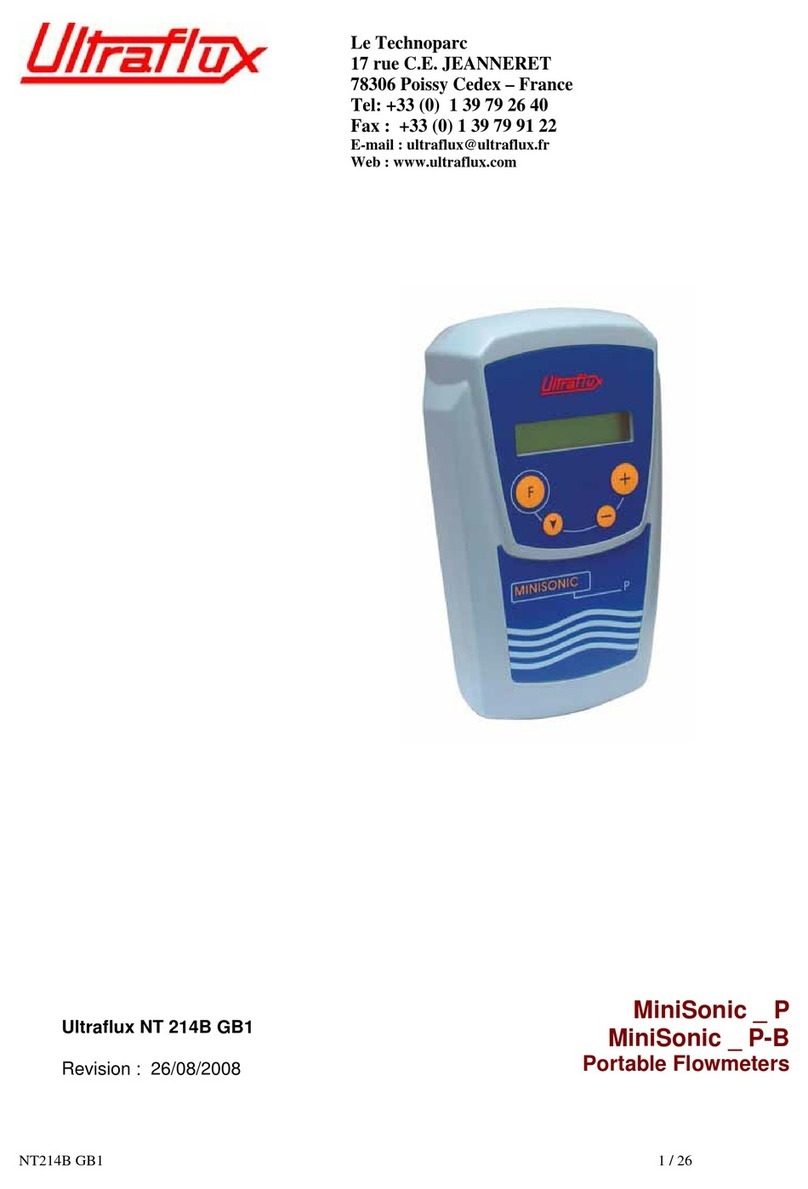
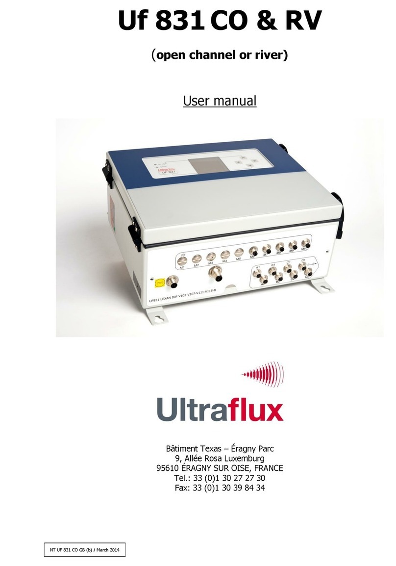
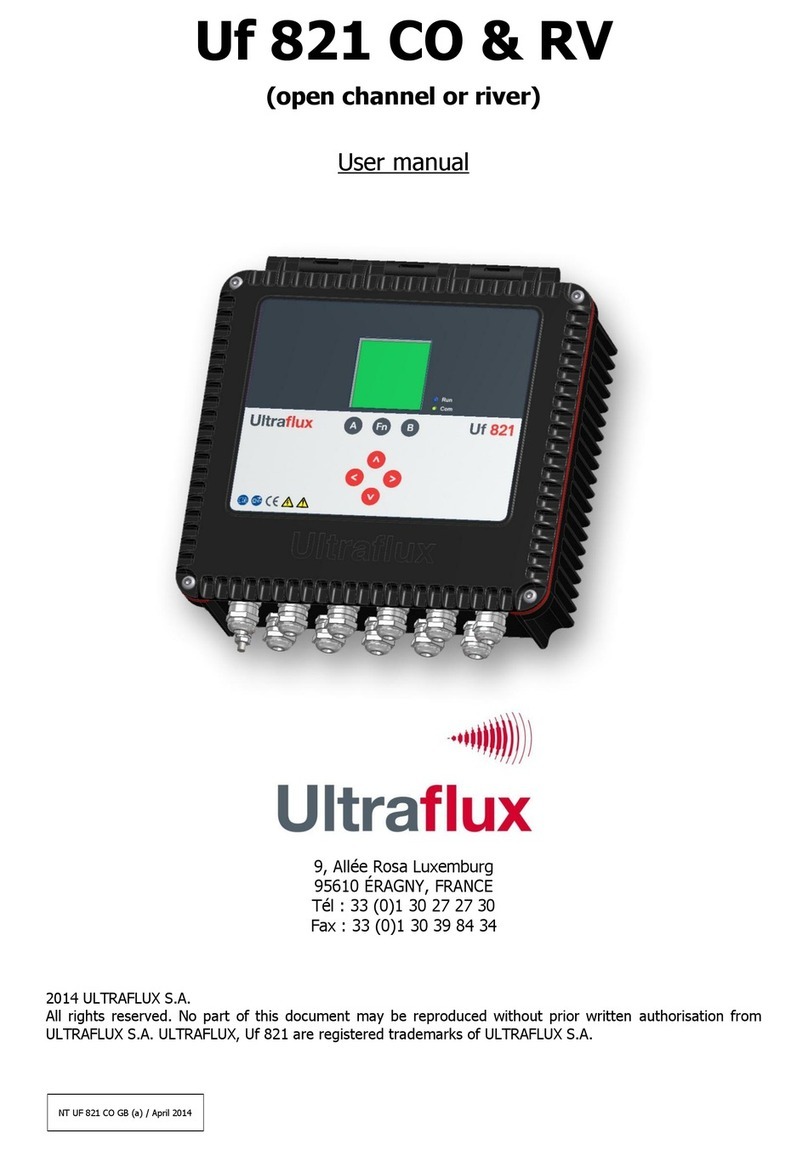
Ultraflux Minisonic II Portable User manual

Ultrasonic flowmeters
Technical manual
Minisonic II
Portable

2
Introduction
Thank you for choosing the Minisonic II Portable; we hope you will appreciate all its metro-logical qualities and ease of use.
The purpose of this manual is to guide you as simply as possible towards using the instrument confidently to achieve results
that match your expectations.
Specializing in ultrasonic flow meters since 1974, Ultraflux develops, manufactures and sells solutions based on the principle
of dierential ultrasonic transit times.
This method provides non-intrusive, constant and bi-directional flow measurements.
Ultraflux flow meters allow non-intrusive or intrusive, constant or occasional flow measurements on any type of homogeneous
fluid (liquid or gas) and through any type of homogeneous material.
Always aiming to better serve its customers’ needs while preserving the environment, Ultraflux has been committed for many
years to a quality improvement and sustainable development policy.
Since it started in 1974, Ultraflux has developed and manufactured all its products in France, in order to ensure that its
production processes are reliable and meet the standard required.
ISO certification
Ultraflux is certified ISO 9001 and ISO 14001.
You can download our certificates via the below links: ISO9001 – Ultraflux certificate ISO14001
Ultraflux quality certificates
ATEX certifications
Some Ultraflux products are also certified for use in ATEX explosive atmospheres. Download the ocial documents:
Ultraflux ATEX Certification Ultraflux ATEX Notification

3
Contents
Introduction 2
Contents 3
Safety instructions 4
CE marking 5
Contact address 5
Recycling the device 6
Connecting the inputs / outputs 7
Power supply and battery charging cable 8
Pulse and analog outputs 9
Measuring probes connector 10
USB connector 11
Applying a measuring point 12
Creating a measuring point 12
Choosing a location for the probes 12
Choosing a measuring mode 13
Positioning the probes 13
Take readings on straight pipe runs 14
Selecting the probe type 17
Fitting the probes and connecting them 18
Configuring the Minisonic 19
Description of navigation 19
Presentation of the measurement screens 22
Configuration menus 23
Set-up example 32
Low power mode 34
Software update procedure 36
Logger / Data upload and exploitation 38

4
Safety instructions
Using the device
Equipped with ultrasonic probes, the device measures the flow of a fluid (gas or liquid) in a pipe. The device must be properly
configured to obtain correct results.
You are recommended to have the device configured by qualified Ultraflux personnel. This is strongly recommended if your
equipment is used to regulate a process, as part of a monitoring system or in the case of other applications where an incorrect
flow measurement would carry a risk.
In normal operation, the device should not become so hot as to cause burns. No special precautions are required to allow it
to cool down. If the temperature of the enclosure should become abnormally high, it is essential to switch o the device and
send it to Ultraflux for expertise. If the device should catch fire, switch it o without opening or touching it, then call the
relevant departments to protect the premises.
The device must not be used beyond the capacities and specifications indicated in this manual. It should be stored in a dry
place. It is recommended that you wear suitable PPE (Personal Protection Equipment) when handling and installing the de-
vice.
The device may only be modified or disassembled by Ultraflux personnel, otherwise, Ultraflux declines all liability.
Connectors must be plugged in and removed with the device switched o and isolated. Ultraflux cannot be held responsible
for incidents caused by failure to follow these instructions.
Equipment connected to the device
All equipment connected to the device must comply with the applicable safety standard and be equipped with safety ex-
tra-low voltage (SELV) circuits (double insulation between the primary and secondary).
Maintenance of the device
Maintenance operations on the device may only be carried out by Ultraflux personnel (after-sales service), using only parts
supplied by Ultraflux.
Temperature limits for the Minisonic II converter
Use from - 20°C à 50°C
Charging from 0°C à 45°C
Storage from -20°C à 50°C

5
CE marking
Ultraflux Minisonic II Portable flowmeters comply with CE certifications.
EN 55016-2-1 Conducted emissions measurements - criterion A
EN 55016-2-3 Radiated emissions measurements from 30MHz to 6GHz
EN 61000-4-6 Immunity to induced conducted disturbances - Criterion B
EN 61000-4-2 Immunity to electrostatic discharges - Criterion B
EN 61000-4-3 Immunity to radiated electromagnetic fields - Criterion A
EN 61000-4-4 Electrical Fast Transient / Burst Immunity - Criterion B
EN 61000-4-5 Surge immunity - Criterion B
IEC 60529 Degrees of protection provided by enclosures (IP Code)
Contact address
For any request for information, do not hesitate to contact us:
Postal address
Bâtiment Texas
9 Allée Rosa Luxemburg
Éragny Parc – Parc des Bellevues
95610 Éragny sur Oise
Delivery address
Bâtiment Texas
9 Allée Rosa Luxemburg
Éragny Parc – Parc des Bellevues
95610 Éragny sur Oise
After-sales
sav@ultraflux.fr
+33 (0)1 30 27 29 30
Email address contact@ultraflux.fr

6
Recycling the device
In accordance with decree no. 2005-829 of 20 July 2005 and decree no. 2009-1139 of 22 September 2009 concerning the
obligations to collect, treat and dispose of electrical and electronic equipment, batteries and accumulators in France, Ultraflux
delegates responsibility for the financial and logistical recovery to users who will manage their waste themselves. Separate
collection and recycling of your waste at the moment of disposal will help preserve natural resources and guarantee recycling
respectful of the environment and human health. For more information on the recycling centre nearest to your site, contact
your City Hall or waste disposal department.

7
Figure 2 - Connectors on the lower face
Figure 1 - Connectors on the upper face
Power supply connectorProbe connector
USB connector Output connector
Connecting the inputs / outputs

8
Power supply and battery charging cable
Figure 3 - Power supply connector
Charging the Minisonic II
Plug the charger into a 100-240V ac 50/60 Hz mains supply, then insert the plug in the power supply connector. The green
«Charging» LED should come on. It goes out when charging is complete.
You can check the device’s charging progress on the information screen.
Important:
Using a power supply dierent from the one supplied with the device is not covered by the Ultraflux guarantee.
Battery pack service life
The battery pack service life depends on the number of charge/discharge cycles. The service life may be shortened by in-
correct use or maintenance. For example, if the batteries are left discharged for a long period of time or are subjected to
incomplete charge/discharge cycles.
The battery pack can be replaced. Although this is expected and easy to do, nevertheless it must be done in our workshops
for it to be covered by our guarantee.
We cannot be held responsible for any unauthorized operation.

9
Pulse and analog outputs
Figure 4 - Connector outputs
Pin Function Wire
1 -
2 -
3 -
4 Pulse output A
5 Pulse output A
6 Pulse output B
7 Pulse output B
8 Analog. output -
9 Analog. output +
10 P 24 V - ISO 3
11 -
12 -
Analog output -
Analog output +
Wires to be used on the Minisonic II to go to a reciever that sup-
ply the power to the measurement loop (Minisonic II : 4-20 mA
passive)
Output P24v ISO3
Analog output +
Wires to be used on the Minisonic II to go to a reciever that
do not supply the power to the measurement loop (Minisonic II :
4-20 mA active)
Passive analog output
Active analog output

10
Measuring probes connector
The device is fitted with a connector to accommodate a pair of probes which are linked by a Y-cable.
Figure 7- Probe connector and connection «Y» cable
1
2
Tags on the wires stand for:
1 Connector to be plugged on the UPSTREAM sensor
2
Connector to be plugged on the DOWNSTREAM sensor

11
Figure 8- USB connector and Adapters: USB Key
USB connector
The device can be used like a USB key on a computer or a USB key may be connected through an adapter to it for file trans-
fers.

12
Applying a measuring point
Creating a measuring point
In addition to the flow meter, there are certain items required, when creating a measuring point
• A pair of probes
• A positioning terminal board
• A Y-cable supplied with the device
• All the accessories supplied in the case (Coupling gel...)
Figure 9- Terminal board with probes and Y-cable
Choosing a location for the probes
The following paragraphs set out the main precautions to be taken when choosing a location for the probes.
To achieve the most accurate measurement possible, it is necessary to have what is called ‘a developed flow profile’. The aim
is to obtain a hydraulic profile which is as predictable and symmetrical as possible.
Figure 10a- Symmetrical hydraulic profile Figure 10b- Asymmetrical hydraulic profile

13
Choosing a measuring mode
The external probes may be installed in dierent ways, depending on the number of times the ultrasonic wave reflects o the
pipe wall. There are four programmable types in the device.
«Direct» or «/» mode «Reflex» or «V» mode
«N» mode «W» mode
Figure11 - Summary of mounting modes
V mode is to be preferred, since it is suitable for use in the majority of cases.
The longer the path, the more eective the measurement principle. (Significant up and downstream transit time dierence).
However, the ultrasonic echo weakens as the distance increases and will therefore be dicult to process. A
compromise must therefore be found between precision and ease of transmitting and receiving the ultrasound waves. This
compromise depends on the application (fluid, wall quality, diameter, etc.).
In practice, multiple reflection modes are reserved for smooth pipes with no clogging or corrosion.
Positioning the probes
Measuring probes must be positioned in such a way as to avoid zones where there is a risk that air bubbles or sediment could
be present.
Figure 12- Asymmetrical hydraulic profile

14
Measurement close to an elbow
Take readings on straight pipe runs
The rules to be applied to obtain the ideal measurement conditions, depending on the arrangement of the pipes, are known.
The following paragraphs provide information on the general rules to be followed.
The following indications show, for liquids, the minimum distances (L) to be complied with before and after a disturbance
depending on the pipe’s inside diameter (D), so that the errors induced by these disturbances remain less than ±1 %.
V «Reflex» mode : Distance > (3x) the diameter of the pipe
/ «Direct» mode: Distance > (5x) the diameter of the pipe
V «Reflex» mode : Distance > (15x) the diameter of the pipe
/ «Direct» mode: Distance > (20x) the diameter of the pipe
V «Reflex» mode : Distance > (15x) the diameter of the pipe
/ «Direct» mode: Distance > (20x) the diameter of the pipe
V «Reflex» mode : Distance > (3x) the diameter of the pipe
/ «Direct» mode: Distance > (5x) the diameter of the pipe
V «Reflex» mode : Distance > (15x) the diameter of the pipe
/ «Direct» mode: Distance > (20x) the diameter of the pipe

15
Measurement close to a valve
Measurement close to a divergent.
Measurement close to a convergent.
V «Reflex» mode : Distance > (15x) the diameter of the pipe
/ «Direct» mode: Distance > (20x) the diameter of the pipe
V «Reflex» mode : Distance > (5x) the diameter of the pipe
/ «Direct» mode: Distance > (8x) the diameter of the pipe
V «Reflex» mode : Distance > (30x) the diameter of the pipe
/ «Direct» mode: Distance > (40x) the diameter of the pipe
V «Reflex» mode : Distance > (3x) the diameter of the pipe
/ «Direct» mode: Distance > (5x) the diameter of the pipe
V «Reflex» mode : Distance > (10x) the diameter of the pipe
/ «Direct» mode: Distance > (15x) the diameter of the pipe
V «Reflex» mode : Distance > (3x) the diameter of the pipe
/ «Direct» mode: Distance > (5x) the diameter of the pipe

16
Note:
The values given must be multiplied by 2.5 for gases.
Convergents with an overall angle less than 16° are ignored and are considered as straight runs (this is not the case for di-
vergents).
Locations not recommended:
Vertical pipe with downflow, especially in where there is a free flow
Recommended locations:
Pipes with upflow.

17
Selecting the probe type
The two probes are chosen to suit the pipe diameter.
The probe frequency has an important eect on measurement quality (see main measurement index).
The Minisonic can be used with a number of probe types which are adapted to the dierent pipe diameter ranges.
The table below sets out the average usage ranges for probes according to their frequencies.
Frequencies Pipe diameter
2 MHz 10 - 100 mm
1 MHz 40 - 1 000 mm
500 KHz 100 - 10 000 mm
Note: The values provided in the table correspond to the pipe inner (nominal) diameter.
Figure 13- Probes for portable
2 MHz 1 MHz 500 kHz

18
Fitting the probes and connecting them
The probes (sensors) must be installed and aligned very carefully in order to obtain good flow rate measurement accu-
racy.
Preparing the pipe
To install external (clamp-on) probes, thoroughly clean the pipe where the probes will be installed. (See distance
between probes ‘here’.) The pipe must be cleaned with absorbent paper or a piece of cloth. If the pipe is very dirty or
corroded, use a wire brush or a scraper. There is no need to remove sound paint. It is even recommended that you leave
it in place to prevent any corrosion. The same applies for most plastic coatings. However, if the paint is blistered and
comes away easily (test it by scraping with your nail or a pointed tool), remove it from the local area. Porosity impairs
the propagation of ultrasound waves.
Fitting the probe
First move the probes apart to the distance calculated by the device.
Then apply coupling gel on the probe/pipe contact surface.
Attach the probes to the pipe using straps or a dedicated support. Check the presence and continuity of the coupling
(the formation of a layer of air between the pipe wall and the probe must be avoided at all costs). To avoid this problem,
do not slide the probes too much (which could aect the coupling film).
Figure 14a - Preparing the pipe
Figure 14b - Fitting the probes

19
Configuring the Minisonic
Description of navigation
The Minisonic II Portable is equipped with a screen and a keypad for configuring it and viewing measurements directly.
Keypad
The keypad has seven keys which have dierent uses in dierent menus. However, navigation between the fields and
menus is always based on the same principles:
Switches between the measurement viewing
screens and the main configuration menu
Takes you back to the previous screen.
Changes measuring screen, moves within the
menus or changes parameter values.
Goes into the menus in reverse video and is used
to validate the parameters selected.
The menus detailed in this manual correspond to the
Normal
mode of the setup level menu.

20
2
1
3
4
5
Types of screen
The Minisonic II Portable is based on several types of screen which are encountered during navigation and which
operate in the same way.
Alphanumeric field editing screen:
These screens allow all the device’s alphanumeric fields, such as the name of the pipe, configuration names, etc., to be
edited.
Figure 14 - Alphanumeric field editing screen
0 1 2 3 4 5 6 7 8 9 _ -
ABCDEFGHIJKL
MNOPQRSTUVWX
Y Z . ,
Totalisateur
<-
Pompe Refoul.
cl
ok
1
Field currently being edited
Totalisateur
<-
Pompe Refoul.
cl
ok
0 1 2 3 4 5 6 7 8 9 _ -
ABCDEFGHIJKL
MNOPQRSTUVWX
Y Z . ,
Allows the field currently being edited to be viewed. A character is selected using the multi-directio-
nal keys; it can then be replaced by selecting a character on the keypad.
2
Alphanumeric keypad
Selects characters to place in the field by pressing «OK».
3
«Delete» key
This key deletes characters in the field being edited.
4
« CapsLock » key
Switches the upper case keypad to a lower case keypad.
5« OK » key
Confirms the field and exits the screen.
Table of contents
Other Ultraflux Measuring Instrument manuals

Ultraflux
Ultraflux Minisonic_600-2 User manual

Ultraflux
Ultraflux UF 831 User manual

Ultraflux
Ultraflux MiniSonic P User manual

Ultraflux
Ultraflux Uf 821 User manual

Ultraflux
Ultraflux UF 831 User manual

Ultraflux
Ultraflux Uf 811 User manual

Ultraflux
Ultraflux Uf 811 CO User manual

Ultraflux
Ultraflux UF 801-P User manual

Ultraflux
Ultraflux UF 801-PB User manual

Ultraflux
Ultraflux Minisonic Series User manual