unication G Series User manual

Please contact us with our Toll Free phone number.:888-657-2963
or leave a message on the Unication Website : http://www.unication.com
or http://www.unicationusa.com
Thank you.
A Complete Paging Solution for all Dispatch
Systems. Dual Band, Dual Protocol.
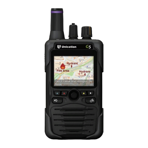
Fire Area
Hydrant
Hydrant
1901 E Lamar Blvd, Arlington, TX
76006
Provides Analog 2-Tone, P25 Conventional, P25 Trunking(Phase I, Phase II), Dual Band and Dual Protocol
For before your digital upgrade, during your digital upgrade, and after your digital upgrade. A single device with
every coverage.
Provides Fast, Efficient Dispatch
In less than 20 Seconds, dispatch can transmit voice / text / image messages and map information to all personnel.
In less than 30 Seconds, all send / receive acknowledgements will be completely collected.
In less than 40 Seconds, all personnel will have responded with their times of arrival and current status.
Provides Status Information on All Personnel
A constantly updating Duty On / Off, Power On / Off Pager Status System ensures that Dispatch always knows how
many firefighters are on hand, and firefighters always have a clear line of information back to Dispatch, guaranteeing
both efficiency and personnel safety.

INDEX
Content Page
1
2
Preface; Why we design the G series Voice Pager
Part A :
What is the special of G series Voice Pager ?
Part B :
16
26
Part C :
G Series Voice Pager Features & Specifications
Part D :
G Series Voice Pager Operations

Preface; Why we design the G series Voice Pager
Utilizing voice pagers to alert volunteer firefighters of emergency incidents has been a fire
department tradition for decades, and from generation to generation, the unnamed heroes of
volunteer fire departments have given a huge contribution to our society.
Thanks to technological trends, fire department communication systems are moving toward digital
and trunked radio systems, and away from the analog radio system. Firefighter’ s current analog
voice pagers are not capable of use with these new digital communication systems, and radio
manufacturers have made it clear there are no plans to develop a suitable product. The reason,
from a business point of view, is that the number of users and market size, when compared to
other public safety industries, are quite small. This has unfortunately caused a frightening trend
with some volunteer firefighters moving away from emergency paging systems to use substitute
solutions such as alpha pagers, cell phone text messages or smart-phone APPs.
These substitute solutions sacrifice the safety of volunteer firefighters due to the fact that
firefighters receive a paging and go to the incident, put on fire rescue gear and join the fire rescue
mission, and they don’ t know the critical information about the circumstance of the fire venue (e.g.
the usage of the building, the material of the building, whether explosive chemical inside the
building or not. etc.) which easily puts these volunteer fighters into dangerous situation. The critical
information is communicated by rescuers who arrived at the incident prior, and they use the radio
system to communicate with each other. The ability for fire fighters to use their voice pagers to
listen to the on-site radio communications while en route to an incident allows them to understand
critical information about the incident location and on scene information being transmitted. This is
the reason volunteer firefighters have used voice paging, rather than other paging systems, for
decades.
Unication has been dedicated to developing radio systems for 25 years. In the past, we designed
and made M3, M4, and M5 voice pager. We have over 20 years of experience designing voice
pager’ s and have worked hard to implement the features that customers demand. Unication deeply
considered the technology gap of current voice pagers in the market, and we spent three years
developing Unication’ s G-Series Voice Pager, designing it to meet all environments of different
radio communication systems, both now and in the future.
Part A :
1

B1. Unication products are designed to support both current and future fire dispatch
systems and Volunteer Firefighter paging systems.
Based on the Federal's plan, the current communication system will be updated into P25
Trunking radio system adopted by the Public Safety (Firefighters and Police, etc.) so that
communication instance can be increased by roaming. Multi-TGID helps different on-duty
teams to communication with others and save more frequency resources.
The plan is great for the improvement of communication systems, but there are no appropriate
products available for the needs of volunteers on this updated system. Unication values the
safety and contribution of firefighters nationwide, and we have designed the G Series Voice
Pager to make up for the product lacking and offer a solution to volunteer firefighters
nationwide.
B1-1. Currently, the North American fire department communication systems can be classified
as Analog 2 Tones (LB, VHF, UHF),Digital Convention DMR / P25C (VHF, UHF) and
P25 Trunking Pgase 1 / or Phase 2 (700-800 MHz)
B1-2. Voice Pager for Volunteer Firefighter Dispatch System is Analog 2 Tones (LB, VHF, UHF)
only
B1-3. This situation causes some regional fire stations in Convention Digital (P25C / DMR) P25
Trunking system to not receive instant communication and information from the fire
location when firefighters are en route. It becomes a problem of volunteers' safety.
B1-4. Unication G Series Voice Pager solves all Volunteer Dispatch equipments which can't
receive the instant communication from the spot.
What is the special of G series Voice Pager ?
Part B :
2

Current Fire
Communication System
Volunteer
Dispatch System Suggested types
of Unication Pager
Now
1
2
3
4
5
6
7
In the following
3 years
Now In the following
3 years
Analog 2 Tones
( LB, VHF, UHF )
Analog 2 Tones
( LB, VHF, UHF )
Analog 2 Tones
( LB, VHF, UHF )
Convention Digital
( VHF, UHF )
Convention Digital
( VHF, UHF )
P25 Trunking
( Phase#1 )
P25 Trunking
( Phase#1 )
Not change
Not change
Not change
It will be turned to
Conventional
Digital (DMR /
P25C)
P25 Trunking
Phase#1 or
Phase#2
P25 Trunking
Phase#1 or
Phase#2
P25 Trunking
Phase#2
Analog 2 Tones
Analog 2 Tones
Analog 2 Tones
(Adopt mobile
phone text
message)
(Adopt mobile
phone text
message)
(Adopt mobile
phone text
message)
(Adopt mobile
phone text
message)
Follow the
radio system
Follow the
radio system
Follow the
radio system
Follow the radio
system ( Secure the
safety of Volunteer
Firefighter)
Follow the radio
system ( Secure the
safety of Volunteer
Firefighter)
Follow the radio
system ( Secure the
safety of Volunteer
Firefighter)
Follow the radio
system ( Secure the
safety of Volunteer
Firefighter)
Unication G1
( LB / VHF / UHF )
Unication G3
( VHF / UHF )
Unication G3
( VHF / UHF )
Unication G4
Unication G5 Dual
Band ( VHF+700 /
UHF+700-800MHz )
Unication G5 Dual
Band ( VHF+700 /
UHF+700-800MHz )
Unication G4
( Phase#1 & Phase#2
Available )
3
▀Unication G Series Voice Pager solves all Volunteer Dispatch equipments

B2. G Series Voice Pager adopts the design for running in various kinds of harsh
environment
Generally, volunteer’ s firefighters are most of the user of Voice Pager. Volunteers have their
jobs and dedicate themselves to the society in the free time. The working environment of these
volunteers may be crucial to electronic devices, such as extremely hot summer ( +40˚C ),
frozen cold ( -20˚C ), poured rain or dusted room, which may cause that pagers are broken.
Unication's design of G Series Voice Pager is considered through the thinking of the use in
such kinds of environments.
B2-1. More Robust Housing
G Series adopts rugged outer mechanism and high density elastic rubber so that it can
endure higher pressure and power of crash than the common plastic outer. Based on the
test from Unication's ALT lab, Unication pager can endure the falling from 1.8 m high.
B2-2. More ristric water-proof design ( IP 67 )
G Series is able to work in the Dust Environmental Test Chamber for 8 hours under the
decompression of maximum 2kPa (20mbar).
B2-3. More ristric dust-proof design ( IP 67 )
G Series is able to work in the Dust Environmental Test Chamber for 8 hours under the
decompression of maximum 2kPa (20mbar).
B2-4. Durability while withstanding rough operating environment
Passed by Unication ALT lab and proved by Thermal Shock test
B2-5. Eco-Friendly
It acquired ROHS certification and rechargeable battery is used.
B2-6. Explosion Proof
4

Support for up to 64 Receiving Table ( 32 Zone /
8 Channels per Zone ). Receiving Table can be
set to Single Channel on, Multi-channel, Normal
or Priority Scan.
( Users can switch channel knobs to select
dispatch / On Site, Fire Fighting, Team
Communication Channel, Priority or Normal
Scan Mode to listen to both channels on duty )
B3. Multi-functional receiving table is for users to set up the own receiving mode
B3-1. G Series Voice Pager provides 8 Zones by software settings and 8 channels
corresponding to Channel knobs, which means 64 channels for selecting. (Unication can
modify the provided channels to 256 channels)
B3-2. (a) G4 (G5 Series) 's first 4 zones (A~D) 32 channels' receiving mode must be
programmed in PPS (Pre-programming System). It can't be modified through any
methods but PPS.
(b) The zone E's 8 channels can be planned only for Control center's use. It can be
programmed, increased, modified or deleted through OTAP (on the air
programming).
(c) The last 3 zones ( F、G、H ) can be for Scanner mode used and set by users. Users
can assign the frequency scanned by first scan mode to a specific channel for next
use. Users can switch the channel knobs to the channel assigned by the frequency
and start their control. Users can also assign a new frequency to that used channel.
B3-3. Each receiving table can be set (by PPS) as the following receiving mode The detail is as
follows.
5

A
B
C
D
E
F
Conventional
System
Single Frequency
6
System Settings
● There are 4 kinds of settings
Receiving Mode Settings by the
System
●There are 3 kinds of settings
under the conventional system
Receiving frequency and
Bandwidth Setting
●( There are 3 options : 6.25KHz /
12.5KHz / 25KHz )
●Set up corresponding receiving
frequency, transmitting
frequency and bandwidth.
* This setting only appears in the
radio sytem instead of the voice
pager system.
* This setting should not appear in
the catalog of G4/ G5 but only in
the one of U3, U4 and U6 Radio.
Data Rate Settings
There are 3 types of settings
currently:
1. 9.6kbps ( Regular )
2.19.2kbps ( TA Requirement )
Encryption Key Setting
( Remark : G4 / G5 offers AES 256
encryption, every channel possess
individual encryption key)
Set up the encryption type and
decryption key of the channel
(receiving/ transmitting frequency)
(Note 1: It requires coordination with the
encryption device on the transmission
end)
(Note 2: Retain this option in the G4/ G5
PPS but it will be set as default, users
do not need to key in by themselves.
Set up the decryption key of every
receiving channal on the Scan List
(Note: It requires coordination with
transmission end to set the encryption
key)
(Note: Same as E1)
Set up the decryption key of every
receiving channal on the Scan List
(Note: It requires coordination with
transmission end to set the encryption
key)
(Note: Same as E1)
Set up the Data Rate of every
channel (receiving / transmitting)
(Note: The Repeater used should be
matched up)
Set up the Data Rate of every
(receiving / transmitting) channel's
frequency in the Scan List.
Set up every channel in the Scan
List. (Data Rate of receiving/
transmitting frequency)
(Note: The Repeater used should be
matched up)
Set up the Data Rate of every
(receiving / transmitting) channel's
frequency in the Scan List.
Set up every channel in the Scan
List. (Data Rate of receiving/
transmitting frequency)
(Note: The Repeater used should be
matched up)
Set up the transmitting frequency
and bandwidth of the
corresponding receiving frequency
Set up receiving frequency and
bandwidth
Set up the frequency and
bandwidth of the Priority and each
secondary frequency in the Scan
List
Set up every Scan Frequency and
bandwidth in the Scan List
TGID of the receiving channel and
the name of the department which
uses this channel settings
Set up the code of receiving
channel ( e.g. CH14 ) and the
name of the department which
uses this frequency
Set up the code of priority
receiving channel and the name
of the department which uses this
frequency (only one can be
progrmmed)
Set up the code of secondary
receiving frequency (can Set up
more than one) and the name of
the department which uses this
frequency
Setting the code of the channel
that would be received (can be
more than one) and the name of
the department which uses this
frequency
●Pager alerts when the TGID
matches. (Vibration/ Alert Tone/
Display Backlight Colour/ Display
Text Information) Alert mode can
be set by users through PPS.
●The display will show the
frequency, channel information,
name of the department, the
called receiving group and
message receiving time. The
users can see the information in
the Message Box, and set whether
all the information should be
displayed or only few of the items.
Multi-frequency Priority Scan Multi-frequency Priority Scan
▀ Every Receiving Table can be set with the following parameters by PPS in accordance with the users'
requirements to satisfy the users' needs.
7
Every TGID that the users would try to listen,
can be Set upd with an individual encryption
key.
(Note 1: Individual encryption key programming will
be available with both the software and PPS)
(Note 2: However, it will be set as default and users
do not need to set up by themselves)
Every TGID that the users would try to listen,
can be Set upd with an individual encryption
key.
(Note 1: Individual encryption key programming will
be available with both the software and PPS)
(Note 2: However, it will be set as default and users
do not need to set up by themselves)
Set up the decryption key of every receiving
channal on the Scan List
(Note: It requires coordination with transmission end to
set the encryption key)
(Note: Same as E1)
Set up the Data Rate of every (receiving /
transmitting) channel's frequency in the Scan
List.
Set up every channel in the Scan List. (Data
Rate of receiving/ transmitting frequency)
(Note: The Repeater used should be matched up)
Set up the Data Rate of every (receiving /
transmitting) channel's frequency in the Scan
List.
Set up every channel in the Scan List. (Data
Rate of receiving/ transmitting frequency)
(Note: The Repeater used should be matched up)
Set up the Data Rate of every (receiving /
transmitting) channel's frequency in the Scan
List.
Set up every channel in the Scan List. (Data
Rate of receiving/ transmitting frequency)
(Note: The Repeater used should be matched up)
1. Set up the transmitting frequency and
bandwidth of every site's Control Channel in
the Trunking System
2. Set up the transmitting frequency and
bandwidth of the corresponding receiving of
every district (site)'s Traffic Channel.
Set up the Control Channel of every district
(site) in the Trunking System.
Set up the Control Channel of every district
(site) in the Trunking System.
Set up the code of every site in the Trunking
system (Note: i.e. the code of the Control
Channel Frequency and TGID)
As well as the code of every site's Traffic
Channel
(Note : e.g. A5 represents Area 5, and the frequency,
which is used by the Control Channel of Area A5)
(Note 2 : A5 - CH14 represents the frequency of the
14th Traffic Channel from Area A5)
Set up the spare frequency of Control Channel
in every district (site) ( Assign one of the
frequency from the Traffic Channel )
Free Scan
(AS Scanner)
P25 Trunking
Phase 2 System
Frequency Scan and TGID Scan
Auto Detection
Auto Detection
Base on systemBase on system
P25 Trunking
Phase 1 System

8
▀ Every Receiving Table can be set with the following parameters by PPS in accordance with the users'
requirements to satisfy the users' needs.
G
H
Pager Status operate on customer's radio system
Pager operate on different
system Receiving Table
Setting
Settings of the end of Message
Note: There are 2 ways of how the calls ended
1. Receiving ends after receiving the Ending
Code.
2. Delay N, that it will be ended after a period of
time (users can set the time when there are
no signal. (Ending Code will not be
transmitted in this setting under the
conventional system. It must take the time,
which has no signal received, as an
activation of turning off the speaker, but it is
afraid that is the Hand Time during the
conversation. Therefore, Delay N is used to
handle this. )
Protocols used by each receiving frequency
Settings
( Note:There are 3 types of settings for selecting the
protocols used by every communicating frequency)
1. Every frequency is allowed to be set with one
protocol. The options of protocols are as
follows:
(a) Analog Signal
(a1) CSII (a2) Two-Tone
(a3) 5-Tone (a4) MDC
(a5) CTCSS (a6) CDCSS
(b) Digital Signal
(b1) DMR (b2) P25C
(b3) P25 / Phase#1 (b4) P25 / Phase#2
2. Every frequency can set up Auto Detection
(one of the Analog protocol, and one of the
Digital protocol; The assigned protocols can
be alternated Analog with Digital, however,
there are only some of them cannot be
occurred colaterally.
(1) CT or CD (only one of them can be
chosen)
(2) 2-Tones or 5-Tones (only one of them can
be chosen)
(3) DMR and P25C
(4) P25 Phase#1 and Phase#2), it represents
that it is able to detect the protocol used by
the signal in the air with the device itself, and
based on that protocol to decode and
demodulate.
3. Auto Detection (no additional assigned
protocols) this condition will delay receiving
and it is commonly used with Free Scan
(Scanner)
Set up the protocols used by
the each channel.
Set up the protocols used by
the each channel.
Set up the protocols used by
the each channel.
Multi-frequency priority
scan mode
Single frequency
Receiving Mode
Multi-frequency priority
scan mode
Set up the receiving end
message condition of each
channel
1. Normally the time set
should be longer than the
Hang Time, read the
Selective Code after
that.(That means when
there is a TGID, which is
designated to listen, the
speaker will be turned on.)
1. Set up the ways how should
the Priority channel end, 2
types of castcode settings
are provided, Ending code
will be the first. Once the
Ending code has not been
received, Delay N will be
enabled. (i.e. the device will
be switched to Standby
mode automatically, when
there is no message
received during the time set.)
2. It is not necessary to set the
way how should the signal
end for Secondary
frequency. (Since it will
switch back to Priority
frequency once it is the Stay
Time, no matter there is any
signals or not.
1. Set up the ways of how
should the receiving end for
every Scan frequency.

9
Not Support Not Support
Free Scan
Pager Setting as Scanner
P25 / Phase # 2
Auto Detection
P25 / Phase # 1
Pager Setting operate on Trunking system
1. The way of Ending Code is commonly
used in the Trunking System. After each
receiving device received the Ending
Code, it will swtich back to Control
Channel.
2. However, Delay N should be set up as
well, in order to avoid that the users cannot
receive any Ending Code, when they
moved the another area with weakened
signals. (Ending Code is used together
with Delay N)
3. The definition of Out of Range Alert should
be Delay N→ back to Control channel →
When there is none of the Control Channel
signals found, then activate Scan to (scan)
search for Control Channel from all the
sites. → No signal → send out Out of
Range Alert → Set up the interval time of
the alert based on the PPS.
Not Support

10
▀ Every Receiving Table can be set with the following parameters by PPS in accordance with the users'
requirements to satisfy the users' needs.
I
Pager Status operate on customer's radio system
Pager operate on different
system Receiving Table
Setting
Every receiving group of frequency Settings
1. There are 2 types of receiving groups
settings for every frequency
(a) Monitoring Mode (b) Selective Call
2. Selective Call is set that the talk group ID
(TGID) which would receive a certain specific
frequency.
3. Selective Call can be set more than one
TGID under the conventional system/ Single
frequency, however, since every freqeuncy
can set multiple protocols, so the TGID,
which would be listened, should be matched
up with the set protocols of the frequency to
set up different protocols with the same TGID
coding.
4. When it is in the Multi-frequency Priority
Scan Receiving Mode under the
Conventional system, Selective Call can be
set by Priority frequency normally (i.e.
multiple TGID can be set). However, when it
is with other Secondary frequency, it is
usually set as Monitoring Mode due to the
short stay time and it is unable to catch the
TGID in the Header certainly.
5. Multi-frequency Normal Scan Receiving
Mode in the Conventional system
(Note: the operating methods are different. If there
is signal, the frequency will stay. It will switch to
another frequency when the signal of that frequency
ended (Ending Code or Delay N) If the call has not
ended but the user would try to stop it and switch to
another frequency, please press the Back key.
In these frequencies of Scan, if the protocols
of some of the frequency are set as DMR or
P25C, it can also be set as Selective Call
and numerous TGID can be set. Since the
voice packages will transmit TGID and it can
distinguish Selective Call when it is the
protocols of DMR and P25C. However, if
Analog is being used with that frequency,
only Monitoring Mode can be used.
6. The operation of this Trunking system is
different from the normal Radio Trunking
system.
Multi-frequency priority
scan mode
Single frequency
Receiving Mode
Multi-frequency priority
scan mode
Set up by each channel and
protocols.
(Each channel is allowed to
set Multi-protocol and each
protocol is allowed to set
several TGIDs.)
Set up by each channel and
protocols.
(Each channel is allowed to
set Multi-protocol and each
protocol is allowed to set
several TGIDs.)
Set up by each channel and
protocols.
(Each channel is allowed to
set Multi-protocol and each
protocol is allowed to set
several TGIDs.)

11
Free Scan
Pager Setting as Scanner
P25 / Phase # 2
P25 / Phase # 1
Pager Setting operate on Trunking system
Set up by each channel and
protocols.
(Each channel is allowed to
set Multi-protocol and each
protocol is allowed to set
several TGIDs.)
Set up by each channel and
protocols.
(Each channel is allowed to
set Multi-protocol and each
protocol is allowed to set
several TGIDs.)
Auto Detection

12
B4. Provide a bidirectional communication way instead of one-way broadcast to increase the
sufficiency of the resource of dispatching volunteers. Through the connection between
Voice Pager and Volunteers' mobile phones, the mobile phones can tell Dispatch Center
whether volunteers are on / off duty, out of range, receiving messages and their
reactions to the dispatch messages (Example: Volunteers can answer that they can go
or how long they will arrive there. These messages can be set as can messages in PPS
and programmed into voice pagers. All reactions and situation reports can be collected
and shown through Unication's PS&DRT system)
Volunteer's resource is very precious, so saving resource should be essential. Chinese motto is
said as "Joy comes never more than once but sorrows never come singly", which indicates the
importance of saving resource about equipments.
Current Dispatch Center send one-way messages so that it can't control the quantity of On-Duty
volunteers, the arriving time of these volunteers, the situation of fire spot and the time when fire
disasters happen. It causes that too many volunteers are allocated to slight accidents while few
volunteers are allocated to serious disasters.
For the purpose of solving resource allocation, Unication designs this function to stop the waste
of volunteers' resource.
B4-1. The status of Voice Pager On/Off, On/Off Duty or Out Of Dispatch Center Signal
Coverage Area is sent to Dispatch Center's computers through the Bluetooth in Voice
Pager and mobile phone's network. Dispatchers can know the real time status of each
pager.
B4-2. When Dispatch Center is dispatching, Voice Pager react to Dispatch Center that this
pager receives messages (excluding Off Duty message) Dispatch Center can utilize
Unication PS&DRT to see the statistics of all reaction and status of pagers. The status of
each pager can be observed as well.
B4-3. Volunteers can respond to Dispatch Center whether they go or not by the provided
functions of Voice Pager after receiving Dispatch Center's message. Volunteers can
select can messages to reply to Dispatch Center in the screen of replying messages.
(Note: Currently, Voice Pager provides reply selections (Default) such as "Arrive in 10
minutes". Dispatch Center can also set up can messages and program them into Voice
Pager.)
Unication PS&DRT (Pager Status & Dispatch Response Tracking) collects the status of
each pager (such as how many volunteers receive messages, how many volunteers can
go and how long volunteers arrive there) after volunteers reply to Dispatch Center.

B5. Less waste of report time, less damage to lives and wealth (Provide Text message
receiving function for 911 call center to receive instant text messages and do fire
dispatch)
This function is for the reduction of reporters, dispatching and arriving time. According to the
test result of this function, 3-5 minutes can be saved.
The saving of speed can improve firemen's control of fire disasters to reduce the damage to
lives and wealth.
Unication's Fire Fighting Solution (Two Way Radio System) provides more sufficient function.
B5-1. G series pager provides the function of receiving text messages and photos (this function
is for analog, digital such as DMR/P25C and P25 Trunking system) (P.S Unication's
unique E&TC equipment can also transit Text and Image data in the P25 Trunking Radio
system not supporting text and image)
B5-2. If people call 911, the 911 operators can do one-key operation to send text messages to
dispatch centers through HTML or Email as they are keying in the information from
people. Through the E&TC (Encoder & Dispatch Center) device installed in dispatch
centers, the messages (address of the fire incident) from 911 centers and dispatch
centers can be sent to the nearby fire stations. Fire stations can also call volunteers by
text messages.
B5-3. When fire stations receive dispatch messages, a voice pager charger amplifier installed in
fire stations alerts, and then a scrolling text marquee or screen connected to the charger
amplifier shows the address of accident spot. The charger amplifier's alert can even open
fire stations' garage rolling shutter. Voice Pager Charger Amplifier provides connectable
equipment controlling devices, and it can be customized based on what fire stations
need.
B5-4. When dispatch center call volunteers, voice messages and map having fire incident cam
be sent to voice pagers through Unication E&TC device. This method improves the
speed of arriving the fire incident for volunteers.
B5-5. This function can also be fulfilled in Unication Two-Way radio. Unication Two-Way radio
can show the relatively position of fire incident and fire trucks through GPS. Unication
radio can also show the position of fire hydrant in the range of 1 Km.
13

14
B6. Provide multiple and clear reminders of messages
B6-1. Provide four kinds of reminders for each Dispatch
(a) Alert Tone
(a1) Alert tone can be assigned to different message group
(b) Vibration
(b1) Vibration can be assigned to different message group
(c) Alert tone and vibration
(c1) Alert tone and vibration can be assigned to different message group
(d) Several backlight colors alert
(d1) Different backlight color can be assigned to different message group

1115
B5. Less waste of report time, less damage to lives and wealth (Provide Text message
receiving function for 911 call center to receive instant text messages and do fire
dispatch)
This function is for the reduction of reporters, dispatching and arriving time. According to the
test result of this function, 3-5 minutes can be saved.
The saving of speed can improve firemen's control of fire disasters to reduce the damage to
lives and wealth.
Unication's Fire Fighting Solution (Two Way Radio System) provides more sufficient function.
B5-1. G series pager provides the function of receiving text messages and photos (this function
is for analog, digital such as DMR/P25C and P25 Trunking system) (P.S Unication's
unique E&TC equipment can also transit Text and Image data in the P25 Trunking Radio
system not supporting text and image)
B5-2. If people call 911, the 911 operators can do one-key operation to send text messages to
dispatch centers through HTML or Email as they are keying in the information from
people. Through the E&TC (Encoder & Dispatch Center) device installed in dispatch
centers, the messages (address of the fire incident) from 911 centers and dispatch
centers can be sent to the nearby fire stations. Fire stations can also call volunteers by
text messages.
B5-3. When fire stations receive dispatch messages, a voice pager charger amplifier installed in
fire stations alerts, and then a scrolling text marquee or screen connected to the charger
amplifier shows the address of accident spot. The charger amplifier's alert can even open
fire stations' garage rolling shutter. Voice Pager Charger Amplifier provides connectable
equipment controlling devices, and it can be customized based on what fire stations
need.
B5-4. When dispatch center call volunteers, voice messages and map having fire incident cam
be sent to voice pagers through Unication E&TC device. This method improves the
speed of arriving the fire incident for volunteers.
B5-5. This function can also be fulfilled in Unication Two-Way radio. Unication Two-Way radio
can show the relatively position of fire incident and fire trucks through GPS. Unication
radio can also show the position of fire hydrant in the range of 1 Km.

Part C :
G Series Voice Pager Features & Specifications
System Spec. and Feature Details
P25 Trunking (Phase I, Phase II)
Unication P25 Trunking
Unication DMR Trunking
Trunking Mode
only
Conventional
and Talk arround
Mode only
Trunking and
Convention Mode
all are Available
Available
Channel Number
setting
Available
Channel Band
Width
Available
Receiving Table
setting
Analog only (Available Protocol)
(1) CT / CD ( in P25 System for Mutual Aid ) PPS
selectable
(2) either 2-Tones or 5-Tones PPS selectable
(3) CSQ ( Carrier Squelch )
(4) Unication DVOA ( Digital Voice Over Analog )
(5) MDC 1200
(6) Pager Auto Detection (1) (2) (3) (4)
Digital only (Available Protocol) :either P25 or
DMR (Option)
Both Digital or Analog are available A2-1 Auto
Detection and Demodulation
User can switch channel knob to selected system
Trunking ( P25 / DMR ) and Conventional ( P25 /
DMR / Analog
※Since user selected Conventional mode, the
available protocol as A2-3.
512 Receiving Table setting (54 via PPS / 8 for
user manual setting ( at free scan feature) )
8 ( CH ) x 64 (Zone), support 512 channels
20 KHz / 12.5 KHz / 6.25 KHz
a. Available Dispatch and on site Radio System
b. Receiving Feature
G3 - AG2 - A G4 - AG4 G5 G5 - A
VHF /UHF
UHF + VHF / VHF + UHF
700/800 MHz
700/800 MHz + VHF
700/800 MHz + UHF
Phone APP
G2 Single Band Support
G3 Dual Bamd Support
G4 Single Band Support
G5 Dual Band Support
G*- A Support
16

Features
System Spec. and Feature Details
Available Receiving Message Type : Voice / Text / image
Re-get unclear received : Dispatch message unclear received auto
requiest "Resent" amd auto get clear message from PSDRT
system including site address ( Cellphone APP )
Quick Call II over P25 Feature
Call Alert Feature
When receiving a clear dispatch message, the pager will auto
acknowledge back to dispatch through the PS&DRT system.
The pager can manually transmit a canned acknowledgement
message through the phone app PS&DRT back to dispatch.
Encryption AES-256
Power tun on auto self test function
Pager status bar display function
When user switches the " Duty ON/OFF " status,the pager will
auto acknowledge and inform the dispatch center (PS & DRT)
The “Out of Range” feature will remind the user and also inform
this status to the dispatch center (PS & DRT)
Multi Channel priority Scan (main
channel with TGID) ( Secondary
channel monitoring only )
Multi Channel Normal Scan
(Monitoring only)
Free Scan (Full Band 2.5KHz a step /
monitoring only)
Operate in
Convention
System
b. Receiving Feature
c. Unique Features
d. Others Features
Available Receiv-
ing Mode setting
in each Receiv-
ing Table
Operate in
Trunking
System
Single Channel (with multi TGID)
Multi-TG Scan
Monitor Mode
System Spec. and Feature Details
G3 - AG2 - A G4 - AG4 G5 G5 - A
VHF /UHF
UHF + VHF / VHF + UHF
700/800 MHz
700/800 MHz + VHF
700/800 MHz + UHF
Phone APP
G2 Single Band Support
G3 Dual Bamd Support
G4 Single Band Support
G5 Dual Band Support
G*- A Support
17

Features
Since dispatching message, receiving LCM Backlight and Alert tone
will follow different dispatch channel ID, shows out different color
backlight and alert tone which is assigned by PPS.
Today:
Unread message display
Unacknowledged message display
Alarmed message and memo display
Function Settings:
• Display contrast
• Display brightness
• Auto power On/Off time setting
• On / Off Duty time setting
• Near field wireless communication device on / off selected
• Alarm setting
• Text font size setting
• Receiving portfolio manual selection
• Alert Mode setting (Vibrator, alert tone, both or silent)
• Unread / UnAck meesage remind
• SQ level
• Clear Memory
Function Setting status display:
• Auto power On/Off status
• Duty On / Off status
• Alarm On / Off status
• Key tone On/ Off
• Alert Mode
Voice Memo function:
• Memo recording
• Memo review / play / delete
• Memo alert time setting
d. Others Features
Standby Receiving Table status display function
Dispatch CH cap code display
Voice / Text / Image review, play and delete
Free Scan
Receiving Table setting by knob, which support dual band, digital /
analog mode
G2
- A
G2
- A
G4
- A
G4 G5 G5
- A
System Spec. and Feature Details
VHF /UHF
UHF + VHF / VHF + UHF
700/800 MHz
700/800 MHz + VHF
700/800 MHz + UHF
Phone APP
G2 Single Band Support
G3 Dual Bamd Support
G4 Single Band Support
G5 Dual Band Support
G* - A Support
System Spec. and Feature Details
G3 - AG2 - A G4 - AG4 G5 G5 - A
VHF /UHF
UHF + VHF / VHF + UHF
700/800 MHz
700/800 MHz + VHF
700/800 MHz + UHF
Phone APP
G2 Single Band Support
G3 Dual Bamd Support
G4 Single Band Support
G5 Dual Band Support
G*- A Support
18
Other manuals for G Series
2
This manual suits for next models
6
Table of contents
Other unication Pager manuals

unication
unication G4 User manual

unication
unication G4 User manual

unication
unication Messenger m90 User manual

unication
unication Alpha Elegant User manual

unication
unication Alpha Gold User manual

unication
unication Alpha Elegant User manual

unication
unication G4 User manual

unication
unication Alpha Legend User manual

unication
unication E5 User manual

unication
unication G Series User manual