5
Revised 15/12/21
01865 767676
www.unicol.com
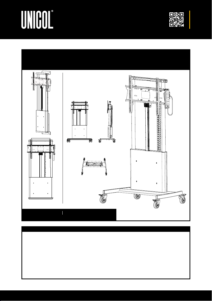
AVMW – STEP 2
Identify floor plate, loosen grub screws to gain
access to bottom holes. Measure 134mm (a) from
the wall. (Consider skirtings). Mark and drill. Using
suitable anchors fix floor plate.
NOTE: The wall has to be capable of supporting 5
times the load of the combined display and unit.
Therefore, it may be necessary to reinforce the floor
and wall before starting this installation.
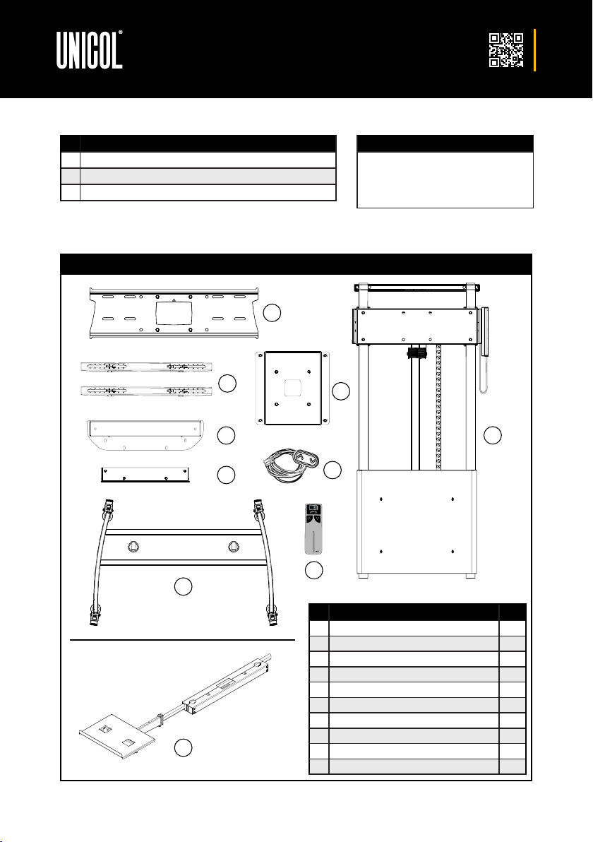
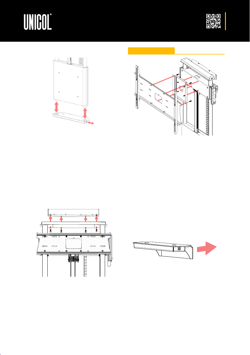
AVMW – STEP 1
The rear of the unit is inaccessible once wall fitted
so it is important to cable up first. (Do not fit screen).
When using a PZX1 or PZX3 for 33-70” screens,
remove rear covers and follow AVMT Steps 2, 3 & 4.
When using a PZX9 for 71-100” screens, remove
rear covers and follow AVMT Steps 2 & 4, but
replace AVMT Step 3 with the above.
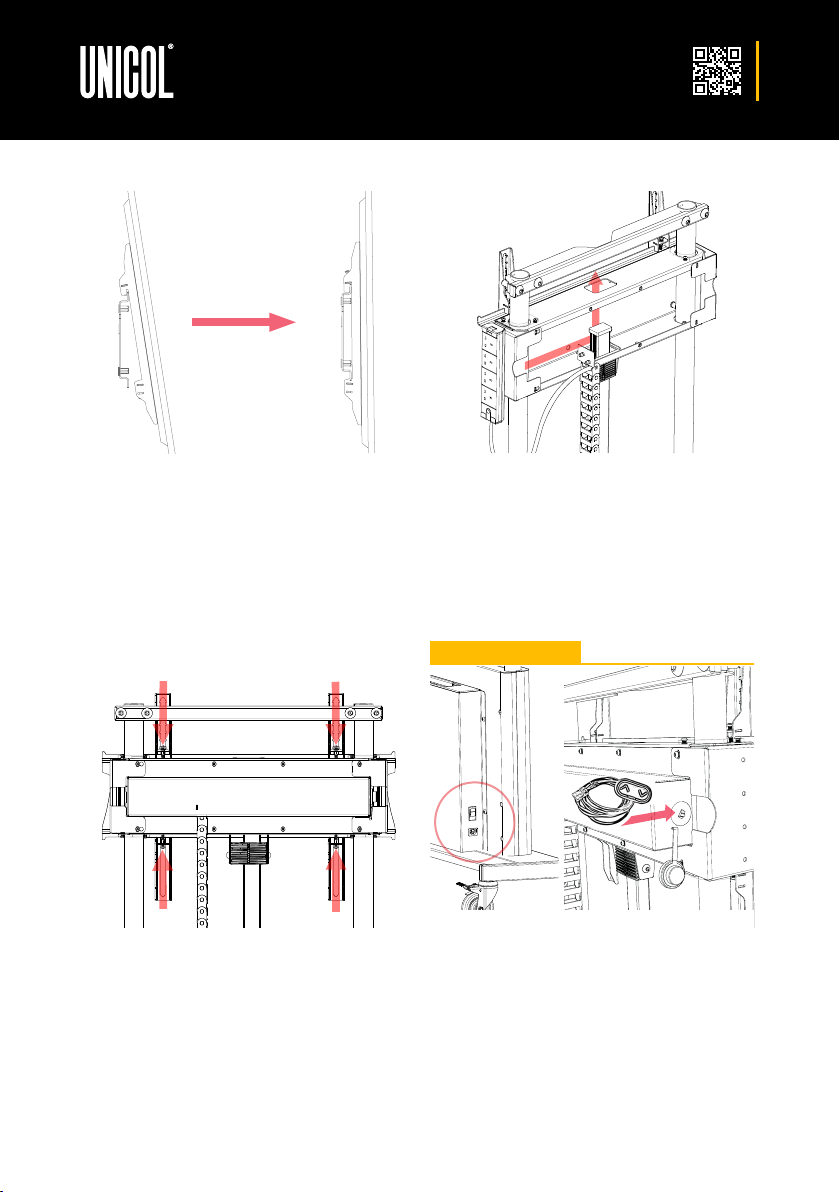
AVMW – STEP 3
Using the 4 x M10 x 25 hex head screws loosely fix
one of the wall brackets to the top plate. Discard
the other wall bracket. There is a small amount of
adjustment in the slots, which can be used when
levelling unit in the next step.
AVMW – FLOOR TO WALL
a
Additional
converter
plate
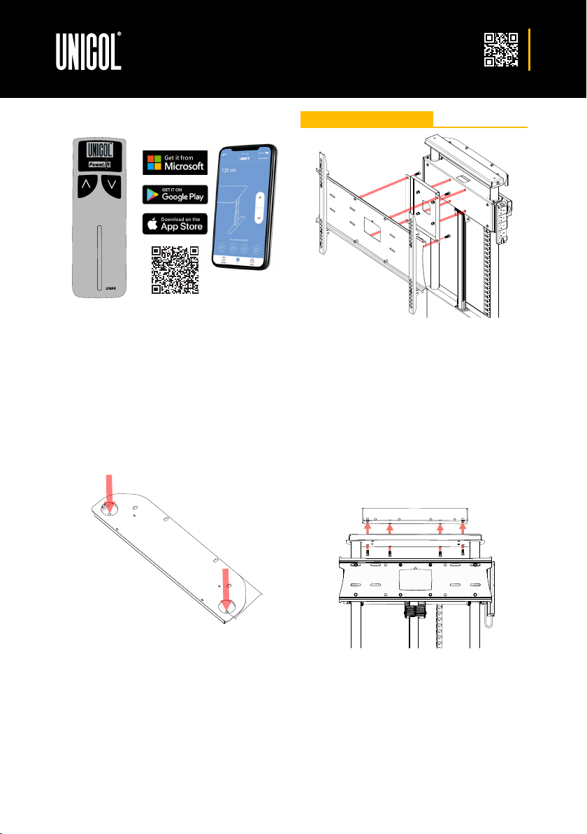
STEP 2
As soon as power is connected you have 3 minutes
to pair the App by pointing your phone at the unit.
When bluetooth has connected your phone press
‘Connect’. Continue to follow the instructions on
the App to operate the unit.
Note: This App was built for desks but is
recommended by LINAK to operate this unit.
Hand Held Remote LINAK Desk Control App