manuals.online logo
Brands
  1. Home
  2. •
  3. Brands
  4. •
  5. unicraft
  6. •
  7. Batteries Charger
  8. •
  9. unicraft MBC-Series User manual

unicraft MBC-Series User manual

MBC 55 S
Operating Instructions
Battery Charger
MBC 55 S
MBC-SERIES
MBC 550 S
MBC 750 S
MBC 550 S
2MBC-Series | Version 1.05
Imprint
Product identification
Battery Charger Item number
MBC 55 S 6850500
MBC 550 S 6850505
MBC 750 S 6850510
Manufacturer
Stürmer Maschinen GmbH
Dr.-Robert-Pfleger-Str. 26
D-96103 Hallstadt
Fax: 0049 (0) 951 96555 - 55
E-Mail: [email protected]
Internet: www.unicraft.de
Indications regarding the operating instructions
Original instruction
Edition: 21.08.2017
Version: 1.05
Language: English
Author: ES/MS
Indications regarding the copyright
Copyright © 2017 Stürmer Maschinen GmbH, Hallstadt,
Germany.
The contents of these operating instructions are the sole
property of the company Stürmer.
Passing on as well as copying of this document, the use
and distribution of its content are prohibited if not explic-
itly permitted. Contraventions are liable to compensa-
tion.
Subject to technical modifications and error.
Content
1 Introduction.................................................................. 3
1.1 Copyright............................................................ 3
1.2 Customer service................................................ 3
1.3 Limitation of liability ............................................ 3
2 Safety ............................................................................ 3
2.1 Symbol explanation ............................................ 3
2.2 Personal protective equipment........................... 4
2.3 Safety labels on the device ................................ 4
3 Intended Use ................................................................ 4
4 Technical Data ............................................................. 5
4.1 Table................................................................... 5
4.2 Type plate........................................................... 5
5 Transport, packaging, storage ................................... 5
6 Description of device .................................................. 5
6.1 Representation MBC 55 S .................................. 5
6.2 Representation MBC 550 S / MBC 750 S........... 6
6.3 Scope of delivery MBC-Series............................ 6
7 Settings and functions ................................................ 6
7.1 Control lights....................................................... 6
7.2 Buttons to select the operating mode ................ 6
7.3 Digital Display..................................................... 7
7.4 Functions and operating modes......................... 7
7.5 Charging mode: „Set Capacity“ ......................... 8
7.6 Saving the charging cycles................................ 8
8 General information for the users.............................. 8
8.1 Nominal capacity of the battery- Ah................... 8
8.2 Principles for charging batteries ........................ 8
8.3 Battery types....................................................... 8
8.4 Supported Batteries............................................ 9
9 Setting up and connecting.......................................... 9
9.1 Connection of the tool......................................... 9
9.2 Electrical connection .......................................... 9
10 Charging ................................................................... 10
10.1 Charging batteries connected to the vehicle . 10
10.2 Charging batteries that are not connected
to a vehicle..................................................... 10
11 Operation.................................................................. 10
11.1 Using the battery charger............................... 10
11.2 End of charging.............................................. 11
11.3 Battery Analysis .............................................. 12
12 Care, maintenance and repair ................................ 13
12.1 Care by cleaning ............................................ 13
12.2 Maintenance and repair ................................. 13
13 Disposal, recycling of used devices ...................... 14
13.1 Decommissioning........................................... 14
13.2 Disposal of electrical equipment.................... 14
14 Spare parts............................................................... 14
14.1 Ordering spare parts ...................................... 14
14.2 Spare parts drawings ..................................... 15
15 Electrical circuit diagrams...................................... 18
15.1 Electrical circuit diagram MBC 55 S............... 18
15.2 Electrical circuit diagram MBC 550 S............. 19
15.3 Electrical circuit diagram MBC 750 S............. 20
16 EC Declaration of Conformity................................. 21
Introduction
MBC-Series | Version 1.05 3
1Introduction
You have made a good choice by purchasing the UNI-
CRAFT battery charger.
Read the operating manual thoroughly before commis-
sioning the machine.
It gives you information about the proper commissio-
ning, intended use and safe and efficient operation and
main-tenance of your battery charger.
The operating manual is part of the battery charger pac-
kage. Always keep this operating manual in the location
where your battery charger is being operated. All local
accident prevention regulations and general safety in-
structions for the operating range of your battery char-
ger must also be complied with.
1.1 Copyright
The contents of these instructions are copyright. They
may be used in conjunction with the operation of the
battery charger. Any application beyond those descri-
bed is not permitted without the written approval of Stür-
mer Maschinen GmbH. For the protection of our pro-
ducts, we shall register trademark, patent and design
rights, as this is possible in individual cases. We
strongly oppose any infringement of our intellectual pro-
perty.
1.2 Customer service
Please contact your dealer if you have questions con-
cerning your battery charger or if you need technical ad-
vice. They will help you with specialist information and
expert advice.
Germany:
Stürmer Maschinen GmbH
Dr.-Robert-Pfleger-Str. 26
D-96103 Hallstadt
Repair service:
Fax: 0049 (0) 951 96555-111
E-Mail: service@stuermer-maschinen.de
Internet: www.unicraft.de
Spare part orders:
Fax: 0049 (0) 951 96555-119
E-Mail: ersatzteile@stuermer-maschinen.de
We are always interested in valuable experience and
knowledge gained from using the application which
then could be shared and be valuable to develop our
products even further.
1.3 Limitation of liability
All information and notes in these operating instructions
were summarised while taking applicable standards
and rules, the state-of-the-art technology and our long-
term knowledge and experiences into consideration.
In the following cases the manufacturer is not liable for
damages:
- Non-observance of the operating instructions,
- Inappropriate use
- Use of untrained staff,
- unauthorised modifications
- technical changes,
- Use of not allowed spare parts.
The actual scope of delivery may deviate from the ex-
planations and presentations described here in case of
special models, when using additional ordering options
or due to latest technical modifications.
The obligations agreed in the delivery contract, the gen-
eral terms and conditions as well as the delivery condi-
tions of the manufacturer and the legal regulations at the
time of the conclusion of the contract are applicablen.
2 Safety
This section provides an overview of all important safety
packages for the protection of the operating personnel
as well as for safe and fault-free operation. Other task
based safety notes are included in the paragraphs of
the individual phases of life.
2.1 Symbol explanation
Safety instructions
The safety notes in these operating instructions are
highlighted by symbols. The safety notes are introduced
by signal words which express the concern of the risk.
DANGER!
This combination of symbol and signal words indi-
cates an imminently dangerous situation which may
lead to death or severe injuries if they are not
avoided.
WARNING!
This combination of symbols and signal words indi-
cates a possibly dangerous situation which may
lead to death or severe injuries if they are not avoi-
ded.
4MBC-Series | Version 1.05
Intended Use
Tips and recommendation
It is necessary to observe the safety notes written in
these operating instructions in order to reduce the risk of
personal injuries and damages to property.
2.2 Personal protective equipment
The personal protective equipment serves to protect
persons against impairments of safety and health while
working. The staff member has to wear personal protec-
tive equipment while performing different tasks on and
with the machine which are indicated in the individual
paragraphs of these instructions.
The personal protective equipment is explained in the
following paragraph:
2.3 Safety labels on the device
Several safety labels are attached to the battery charger
which must be observed and followed.
The safety labels must not be removed. Damaged or
missing safety markings can lead to incorrect actions,
personal injury and damage to property. They must be
replaced immediately.
If the safety labels are not visible and comprehensible at
first glance, the battery charger must be taken out of
operation until new safety labels have been affixed.
The following safety labels and symbols have been affi-
xed:
Fig. 1: Safety labels on the Battery Charger |
1 Warning of dangerous electrical voltage |
2 Read operating instructions | 3 Notes
3 Intended Use
The battery charger is used exclusively for charging
rechargeable batteries. Ideal for all lead-acid batteries
with free electrolyte (wet) or with fixed electrolyte (dry),
such as hermetically sealed gel batteries.
The battery charger ABC 40 must not be used to charge
non-rechargeable or frozen batteries.
The battery charger may only be operated by persons
who have been instructed on the device.
Intended use also includes compliance with all the infor-
mation in these instructions. Any use beyond the inten-
ded use or any other use is considered misuse. Stürmer
Maschinen GmbH assumes no liability for constructive
and technical changes to the battery charger.
Claims of any kind for damage due to improper use are
excluded.
CAUTION!
This combination of symbol and signal words indi-
cates a possibly dangerous situation which may
lead to minor or light injuries if they are not avoided
ATTENTION!
This combination of symbol and signal words indi-
cates a possibly dangerous situation which may
lead to property and environmental damages if they
are not avoided.
NOTE!
This combination of symbol and signal words indica-
tes a possibly dangerous situation which may lead to
property and environmental damages if they are not
avoided.
Tips and recommendation
This symbol highlights useful tips and recommenda-
tion as well as information for all efficient and
trouble-free operation.
Protective goggles
The protective goggles serve to protect the eyes
against parts flying off.
Protective gloves
The protective gloves serve to protect the hands
against sharp components as well as against fric-
tion, abrasions or deep injuries
Protective clothes
Protective clothes are made of a tightly fitted fabric
without the protruding parts of low tear strength.
12
3
Technical Data
MBC-Series | Version 1.05 5
4 Technical Data
4.1 Table
4.2 Type plate
Fig. 2: Type plate MBC 550 S
5 Transport, packaging, storage
Delivery
Check the battery charger on delivery for any visible
transportation damage. If you notice any damage to the
device please report this immediately to the carrier or
dealer.
Transport
Packaging
All used packaging materials and packaging aids are
recyclable and should be taken to a materials recycling
depot to be disposed of.
The delivery packaging is made of cardboard, so
please dispose carefully by having it chopped up and
given to the recycling collection.
The film is made of polyethylene (PE) and the cushioned
parts of polystyrene (PS). These materials should be
taken to a collection point for recyclable materials or to
the local waste disposal company.
6 Description of device
Illustrations in these operating instructions may deviate from
the original.
6.1 Representation MBC 55 S
.
Fig. 3: Battery Charger MBC 55 S
1 Handle 5 Digital LED display
2Main housing 6 Positive charging cable
3Positive clamp 7Negative charging cable
4Front cover 8Negative clamp
Model MBC 55 S MBC 550 S MBC 750 S
Voltage 230 V /
50 Hz
230 V /
50 Hz
230 V /
50 Hz
Output 1,5 - 10 kW 1,5 - 10 kW 2,0 - 12 kW
Charging
voltage
12 / 24 V 12 / 24 V 12 / 24 V
Charging
current
50 / 50 A 50 / 50 A 70 / 70 A
Dimensi-
ons
310 x 240
x 400
380 x 310
x 950
380 x 310
x 950
Charging
capacity
4 - 550 Ah 4 - 550 Ah 4 - 700 Ah
Startup
output
300 A 300 A 450 A
Peak
output
400 A 400 A 650 A
Weight 18,9 kg 19,4 kg 29,5 kg
NOTE!
The device should be protected from humidity.
Tips and recommendation
For longer transports, make sure that the corrosion
protection is intact or renewed if necessary.
7
81
2
5
3
6
4
6MBC-Series | Version 1.05
Settings and functions
6.2 Representation MBC 550 S / MBC 750 S
.
Fig. 4: Battery Charger MBC 550 S
1 Handle
2 Positive charging cable
3 Digital LED display
4 Positive clamp
5 Front cover
6 Wheel
7 Negative clamp
8 Negative charging cable
6.3 Scope of delivery MBC-Series
- Battery Charger
- Charging cable
- Clamps
7 Settings and functions
Fig. 5: Control panel MBC-Series
7.1 Control lights
Am Bedienpanel befinden sich 15 LEDs mit folgender
Bedeutung:
4 LEDs for the charge status of the battery:
- Full: battery is charged and is in charge main-
tenance status
- Charging: battery charging
- Fault: battery is damaged
- Reverse: polarity reversal
1 LED battery charger status. LED ON:
- the battery charger is ON (colour BLUE).
1 LED operating status:
- indicates whether output is in accordance with
selected mode. Correlated with the Start/Stop but-
ton (Colour YELLOW).
3 LEDs „Function“ operating mode
- Charge, Start oder Supply (Colour YELLOW):
4 LEDs battery capacity indication „Set Capacity“:
- described in the next section (Colour YELLOW).
2 LEDs battery type indication „Battery Type“:
- described in the next section (Colour YELLOW).
7.2 Buttons to select the operating mode
- Start / Stop: starts or stops supply in the selected
mode
- Function: selects operating mode
- Set Capacity: selects battery capacity
- Battery Type: selects the type of battery to charge
- A/V (display): selects the information to show on the
display
7
81
2
5
3
6
4
1
2
3
Settings and functions
MBC-Series | Version 1.05 7
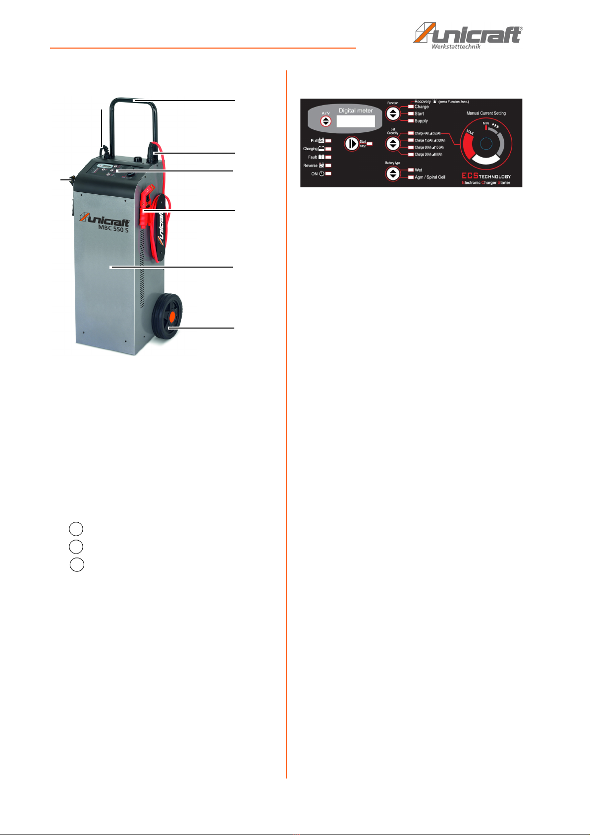
7.3 Digital Display
„A/V“ button:
The „A/V” selector button selects voltage or current dis-
play or allows the user to change the display messages
language. Pressing A/V toggles from voltage display U
to current display A, and finally the „Language“ menu.
This menu will show the message „LANGUAGE = ITA-
LIAN" or another language, depending on the selection.
Change messages language:
To enter the language selection mode, press the „A/V“
button and hold it down when the display is showing the
message „LANGUAGE = ITALIAN“. The language set-
ting is Italian by default; to scroll the language menu
press the „A/V“ button next to the display and the langu-
age shown will change instantly.
Languages supported:
- Italian
- English
Once the language is set, to quit the menu press the
„A/V“ button for a few seconds.
7.4 Functions and operating modes
All operating modes are suitable for 12V and 24V batteries!
Charge:
Battery charging mode. There are 11 phases to char-
ging the battery:
- Phase 1: Analysis 1. If the battery output is less than
10.5V the unit proceeds with the next analysis.
Outputs below 5V will cause the device to revert to
stand-by.
- Phase 2: Analysis 2. (sulphated battery). The display
shows the message "ANALYSIS" alternating with the
instantaneous voltage or current. After this step the
unit either starts the charging cycle directly or it dis-
plays the message "SULPHATED BATTERY" to inform
the operator that the battery must be recovered.
- Phase 3: Desulphation. Pulsed voltage to prevent sul-
phation of the battery.
- Phase 4: Controlled current. Charges the battery up to
the programmed limit value.
- Phase 5: Analysis 3 (elements short circuited). Checks
whether the battery has short circuited elements or is
damaged and reports the error, if present
- Phase 6: Deep Cycle Charging. Central charging cycle.
- Phase 7: Constant Voltage. Keeps the battery at the
charging end voltage.
- Phase 8: Analysis4. Checks whether the battery has
short circuited elements or is damaged and reports
the error, if present.
- Phase 11: Pulsed current cycle. Cycle that simulates the
normal life cycle of the battery.
Start: Method of starting a vehicle with a flat battery. Pos-
sibility of starting also remotely using a pushbutton
external to the battery charger. Composed of the
following steps:
- Step 1: Battery analysis. The device's „Start“ LED
flashes.
- Step 2: Fast Charging. The device enters this step if
the „START“ LED is steady on. It sets the charge
end voltage associated with the selected battery
type with the current limit defined for the „START“
step.
- Step 3: Engine Boost. When the battery charger de-
tects an engine cranking attempt it switches to the
next step. If the battery voltage reading is above
13.5V the scrolling message „START“ appears on
the display, also before the next step.
- Step 4: Boost. The scrolling message „START“ ap-
pears on the display: the battery charger is now
delivering the maximum power.
Supply:
Power supply mode to assist in vehicle programming.
This mode does not contain any charging steps, and it
consists exclusively of a stabilized power supply deli-
vering the nominal battery voltage. The purpose is that
of supplying current to support the battery to prevent it
from being drained during operations that require power
for short or long periods.
Recovery:
Method of recovery for sulphated batteries accessible
by means of a prolonged press of the "Function" button.
On the screen the message RECOVERY alternates with
the instantaneous voltage or current reading; during this
step the "Charge" LED flashes.
The battery charger performs a special charging cycle
in which higher than average voltages are forced to at-
tempt recovery of the battery. In this mode no error mes-
sages are generated during the charging cycle; a mes-
sage is displayed at the end of the cycle to indicate
whether or not the battery has been recovered on the
basis of the current absorption. Mode with 6 charging
steps, as described below:
- Step 1: Analysis1. Outputs below 2V will cause the de-
vice to revert to stand-by.
- Step 2: Desulphation. Pulsed voltage to prevent sul-
phation of the battery.
- Step 3: Controlled current. Charges the battery up to
the programmed limit value.
- Step 4: Deep Cycle Charging. Central charging cycle.
8MBC-Series | Version 1.05
General information for the users
- Step 5: High Voltage. Keeps the battery at high
voltage for 2h to attempt to break down the sul-
phate crystals that have formed in the battery.
- Step 6: Analysis2. Checks whether or not the battery
has been recovered.
7.5 Charging mode: „Set Capacity“
Preset charging bands to select the connected battery,
or for expert users, manual setting of the output current
as a percentage of the maximum current available in the
operating mode currently selected on the battery char-
ger „Manual Current Setting“.
Specifically:
- Charge: settable charging band
- Start: settable charging band
- Supply: non-settable, output current is adjusted
automatically
Charge 4Ah - 550Ah (manual):
Supports all batteries from a minimum of 4Ah up to a ma-
ximum of 550Ah. Possibility of adjusting the output cur-
rent from 0 up to the maximum supported by the opera-
ting mode currently selected on the battery charger.
Charge 150Ah - 300Ah
Suitable for batteries from 150Ah to 300Ah. The char-
ging current is regulated automatically.
Charge 80Ah - 150Ah
Suitable for batteries from 80Ah - 150Ah. The charging
current is regulated automatically.
Charge 30Ah - 80Ah.
Suitable for batteries from 30Ah - 80Ah. The charging
current is regulated automatically.
7.6 Saving the charging cycles
The battery charger saves the settings made on the
control panel of the unit. In the event of an unintentional
interruption of the charging process, the charger will
continue to run with the last stored settings, including
Start/Stop, when it is switched on again.
8 General information for the users
8.1 Nominal capacity of the battery- Ah
Current quantity (A) that a battery is able to supply in the
time (h) normally considered in 10 hours.
8.2 Principles for charging batteries
To charge a battery, the maximum current (A) must be
equal to one-tenth of the nominal capacity (Ah) of the
battery.
For example, a 60Ah battery must be charged with 6Ah
for 10 hours (6A x 10h = 60Ah).
If a current of 4 A is used to charge a 60 Ah battery,
charging will take approximately 15 hours (4 A x 15 h =
60AH), after which the battery is fully charged.
8.3 Battery types
8.3.1 Wet cell batteries
They are lead batteries in which the positive and nega-
tive plates are immersed in an aqueous solution of sul-
phuric acid. They may be hermetically sealed or equip-
ped with caps for maintenance. This is the most popular
type of battery used in vehicles.
8.3.2 Gel cell batteries
Gel batteries are lead-calcium batteries in which the po-
sitive and negative plates are immersed in a gel solution.
They aresealed batteries and are maintenance-free.
They are usually used in situations of intense use of the
battery.
Their robustness makes them particularly suited for use
on motorcycles, off-road vehicles, operating machines
and watercraft.
8.3.3 Dry cell battery
Dry cell batteries are lead-calcium batteries in which the
electrolyte solution is located in the microfibre separa-
tors between the plates. As with gel batteries, these are
sealed batteries with high performance.
ATTENTION!
Because of the high voltage reached during this
charging cycle, the battery recovery process must
be performed with the battery disconnected from the
vehicle. Recovery with the battery connected to
the vehicle may result in damage to the vehicle's
electronics.
NOTE!
The charging time of a battery also depends on the
initial degree of discharge. A heavily charged battery
takes more time to charge than a less discharged
battery.
Setting up and connecting
MBC-Series | Version 1.05 9
8.3.4 AGM battery
AGM batteries are lead-tin batteries with reverse reac-
tion and endless belt, in which the plate, the electrolyte
solution and the polymer fibre and silicone mats are spi-
rally wound. These are maintenance-free batteries with
high peak starting current, specially designed for use
under extreme and heavy conditions. They withstand
the stress of intensive charging and discharging cycles.
The charging time of a battery also depends on how low
the battery charge is at the start of the charging
process. A deeply discharged battery takes longer to
charge than a partially discharged battery.
8.4 Supported Batteries
WET: Acid electrolyte batteries.
AGM batteries with flat plate or Optima type spiral cell.
9 Setting up and connecting
The location for the installation of the battery charger
must be chosen so that the openings for the inlet and
outlet of the cooling air are not restricted.
At the same time, make sure that no conductive dust,
corrosive vapours, moisture or similar are sucked in. At
least 250 mm must remain free around the unit.
9.1 Connection of the tool
9.2 Electrical connection
ATTENTION!
All installation and preparation activities for connec-
ting the device to the power supply must be carried
out only when the device is switched off and dis-
connected from the mains.
The power connections may only be made by autho-
rized electricians.
ATTENTION!
Place the device on a level surface or position it so
that it does not tip over.
Do not use the battery charger inside a car or on the
bonnet. Never place the battery charger on top of
the battery during charging.
Use protective goggles!
Always use protective goggles and keep your face
away from the battery while connecting or dis-
connecting the battery.
ATTENTION!
Before connecting the tool, check that the device is
switched off and that the mains plug is dis-
connected.
The two output terminals must not come into contact
with each other.
CAUTION!
The fluid inside the battery is corrosive. In case of
any contact with eyes or skin, rinse immediately with
plenty of water and seek medical attention.
CAUTION!
While the battery is charging, explosive gases may
escape, so avoid open fire and sparks and do not
smoke.
NOTE!
The plug can only be plugged into the socket in one
direction.
DANGER!
Danger to life from electric current!
Contact with live components may result in direct
danger to life due to electric shock.
- Work on the electrical system must only be carried
out by qualified electricians.
ATTENTION!
Make sure that the charging terminals do not touch
when connected to the mains and that they are
connected to the battery.
10 MBC-Series | Version 1.05
Charging
10 Charging
10.1 Charging batteries connected to the
vehicle
Before you start to charge the battery, make sure the
power supply lead is NOT plugged into the mains.
Identify which pole is grounded (connected to the chas-
sis), usually the minus terminal.
10.1.1 Charging a battery with negative terminal grounded
to the vehicle’s chassis
Step 1: Connect the charging cable with the red clamp
to the positive terminal (+) of the battery.
Step 2: Connect the charging cable with the black
clamp to the vehicle chassis, but not near the
battery or fuel line.
10.1.2 Charging a battery with an earthed positive terminal
Step 1: Connect the charging cable with the black
clamp to the negative pole (-) of the battery.
Step 2: Connect the charging cable with the red clamp
to the vehicle chassis, but not near the battery or
fuel line.
10.2 Charging batteries that are not connected
to a vehicle
Step 1: Before charging, check that the power cord is
disconnected from the wall outlet.
Step 2: Connect the charging cable with the red clamp
to the positive pole (+) of the battery.
Step 3: Connect the output cable with the black clamp
to the negative pole (-) of the battery.
11 Operation
11.1 Using the battery charger
Step 1: After the charging cables have been connected
to the battery, connect the power cable from the
unit to a power outlet, making sure that the
voltage corresponds to the rated voltage of the
charger (230V-50Hz). The charger beeper will
turn on for 0.5 seconds and the LEDs on the
control panel will turn on for 2 seconds.
Step 2: The charger switches to "Stand-by", e.g.: LED
ON on, LED 12V on, LED Charge 30Ah/80Ah on,
LED Wet on. The switching on of the LEDs varies
depending on the last stored program (see
chapter „Saving charging cycles“)..
Step 3: Using the charger in standby mode and the but-
tons on the control panel, set the charging para-
meters suitable for the battery type. The set
parameters are indicated by switching on the
corresponding LED.
Use protective goggles!
Always use protective goggles and keep your face
away from the battery while connecting or dis-
connecting the battery.
Use protective gloves!
The protective gloves protect the hands from sharp-
edged components as well as from friction, abrasi-
ons or deeper injuries.
ATTENTION!
Charge in a dry environment with adequate ventila-
tion: do not expose to rain or snow.
The two output clamps must not come into contact
with each other.
CAUTION!
Do not usethe battery charger inside the vehicle or
on the motor hood.
ATTENTION!
Make sure that the battery charger is disconnected
from the mains before connecting or disconnecting
the charging cables to or from the battery.
ATTENTION!
The liquid inside the battery is corrosive, in case of
accidental contact with eyes or skin rinse immedi-
ately with water and contact a healthcare profes-
sional.
NOTE!
Make sure that both terminals of the charging cable
are in good contact with the respective terminals
(battery terminals).
Operation
MBC-Series | Version 1.05 11
11.1.1 Charging parameters MBC-Series
Fig. 6: Charging diagram MBC-Series
Selectable parameters
Step 1: Once the charging parameters have been set,
press the START/STOP button to start charging
the battery. Turning on the START/STOP and
CHARGING LEDs indicates that charging is in
progress. The display shows the charging cur-
rent and the battery voltage.
Step 2: When charging the battery, the CHARGING LED
remains on in phases I and U0.
Step 3: When the LED FULL is switched on, the battery
is 100% charged. The charger switches over to
charge conservation, constantly monitors the ef-
ficiency of the battery and maintains an optimum
charge state of the battery. In this phase, the
charger can remain connected for months.
Step 4: If the charging process is to be completed or in-
terrupted, refer to the notes in the END OF
CHARGE section
11.2 End of charging
Step 1: Once the battery is charged, unplug the power
supply cable of the battery charger from the
mains.
Step 2: Disconnect the output cable with black clamp
from the vehicle’s earthing or from the negative
terminal (-) of the battery.
Step 3: Disconnect the output cable with red clamp from
the positive terminal (+) of the battery.
11.2.1 Intentional interruption of the charging cycle
If you want to interrupt the battery charging cycle,
simply press the START/STOP key; the corresponding
LED switches off to point out that the work cycle has en-
ded. At this stage, you are recommended to disconnect
the output leads of the battery terminalsn.
11.2.2 Interruption of the charging cycle in the case of a
mains blackout
In case of power blackout of the 230V power line, the
charger stores the current charging cycle, so that the
charging process can be automatically resumed and
continued as soon as the power supply of the 230V po-
wer line has been restored. This function is particularly
important when charging the battery in the absence of
the operator, for example during very long charging cy-
cles (charge maintenance status) or when charging the
battery overnight (charging the batteries of vehicles re-
quiring daily charging). (The duration of the memory
function of the set parameters is 12 hours, after 12 hours
the charger will in any case continue charging with the
default parameters).
Function
key
According to battery capacity and duty
cycle:
- Charge
- Start
- Supply Recovery
S e t
Capacity
key
- Charge 4Ah -550Ah (manual):
suitable for all batteries from 4Ah to
550Ah maximum. The output current
can be set in a range from 0 to the
maximum value compatible with the
operating mode set on the charger.
- Charge 150Ah - 300Ah: suitable for
batteries from 150Ah to 300Ah. The
output current is regulated automati-
cally.
- Charge 80Ah - 150 Ah: suitable for
batteries from 80 to 150Ah. The out-
put current is regulated automati-
cally.
- Charge 30Ah - 80Ah: suitable for bat-
teries from 30Ah to 80 Ah. The output
current is regulated automatically.
Type key Depending on the constructional tech-
nology of the battery:
- Wet
- Agm
CAUTION!
Always attach the rubber cap to the quick connec-
tor after the charging process has been completed.
12 MBC-Series | Version 1.05
Operation
11.3 Battery Analysis
The analysis stages within the operating modes may ter-
minate with the signalling of various errors.
- Damaged Battery: the „Fault“ LED switches on and the
„Start / Stop“ LED switches off and the battery char-
ger enters Stand-By mode. The display shows the
message „Errx“ where „x“ is the number correspon-
ding to the cause of the error. Single two second
audible signal.
- Polarity reversal: the „Reverse“ LED switches on and
the display shows the message „Err7“with a
twosecond audible signal.
- Analysis step in „Charge“: the display shows the
scrolling message „ANALYSIS“ alternated with the
measured voltage or current value; the LED corre-
sponding to the function continues to flash until the
analysis is concluded. If the battery is in good con-
dition the LED becomes steady on, otherwise the
display shows scrolling message „SULPHATED-
BATTERY“ and an intermittent audible signal is
emitted.
- Analysis step in „Start“: in the preliminary analysis
function in „Start“ the LED of this mode will flash un-
til a current absorption exceeding a minimum th-
reshold.
11.3.1 Error display MBC-Series
Notification Cause Solution
E01 Leads disconnected, leads short-circuited. Position the clamps correctly and start
charging the battery again.
Battery completely short-circuited. The battery could be defective. Contact your
nearest battery service centre.
E02 Battery faulty or unrecoverable.
No current accepted after 10 hours of recovery.
The battery could be defective. Contact your
nearest battery service centre.
E03 Internal overheating of battery charger.
Battery charger overload.
Remove any objects that could be covering
the ventilation area of the battery charger or
move it to a cooler area. Wait for the battery
charger to start again automatically.
E04 Tension Error. Set again the voltage corresponding to that
of the battery. Start charging the battery
again.
One or more elements of the battery has/have
short-circuited.
The battery could be defective. Contact your
nearest battery service centre.
E05 Battery voltage too high compared to that set.
(You are attempting to charge a 24V battery with
the battery charger set at 12 Volt).
Set again the voltage corresponding to that
of the battery. Start charging the battery
again.
E06 Battery capacity excessive.
Unable to reach end condition.
Use a battery charger with greater capacity.
E07 and LED
Reserve (N)
The clamps of the output leads are not connected
correctly to the battery.
Position the clamps correctly and start
charging the battery again.
E08 Excessively high output current.
Current exceeds maximum limit.
Reduce output current when in manual
mode.
Care, maintenance and repair
MBC-Series | Version 1.05 13
12 Care, maintenance and repair
12.1 Care by cleaning
The battery charger must always be kept in a clean
condition.
All plastic parts and painted surfaces should be cle-
aned with a soft cloth.
12.2 Maintenance and repair
- Check the supply cable and the tool cables. They
must be insulated and in perfect condition. Pay spe-
cial attention to the bending points.
- Check the tool. Do not use tool parts with obvious
defects in insulation or sheathing.
- If the protective tapes of the tools have become un-
usable, they must be replaced.
- The charging clamps of the battery charger must be
kept clean and free of corrosion.
- Prevent dirt and dust from entering the battery char-
ger.
- The correct cooling air circulation must always be
ensured.
If the battery charger does not function properly, con-
tact a specialised dealer or our customer service.
Please find the contact data on chapter 1.2 Customer
service.
Immediately reassemble all protective and safety equip-
ment after completing the repair and maintenance of the
device.
Remove dust deposits. Always check that the power
connections are properly seated and that the cables
have no damage to the insulation.
After completion of maintenance or repair, the connec-
tions and cabling must be set back to their original con-
dition. Ensure that they do not come into contact with
parts that can reach high temperatures. Bundle all con-
ductors as before, making sure that the high voltage ter-
minals of the primary transformer are kept separate from
the low voltage terminals of the secondary transformers.
Use all original washers and screws to close the
housing.
ATTENTION!
Before starting cleaning, maintenance and repair
work, make sure that the device is switched off and
disconnected from the mains.
NOTE!
Repairs or maintenance work on the device may only
be carried out by qualified personnel.
Use protective gloves!
NOTE!
Never use aggressive cleaning agents for any
cleaning work. This can damage or destroy the
device.
When not in use, store the battery charger in a dry
place to avoid moisture.
NOTE!
Misuse of the battery charger or opening the elec-
tronic circuit inside the unit will void the warranty.
ATTENTION!
If the cable of the device is damaged, it may only be
replaced by a special workshop authorised by the
manufacturer, as special tools are required.
ATTENTION!
The following maintenance work can be carried out
by the operator of the device:
ATTENTION!
All other maintenance and repair work may only be
carried out by qualified personnel.
ATTENTION!
Before starting maintenance and repair work, check
that the mains plug is disconnected.
ATTENTION!
Do not direct the compressed air jet onto the circuit
boards. These must be cleaned with a very soft
brush or suitable solvents.
14 MBC-Series | Version 1.05
Disposal, recycling of used devices
13 Disposal, recycling of used devices
Please take care in your own interest and in
the interest of the environment that all com-
ponent parts of the machine are only dis-
posed of in the intended and permitted way.
13.1 Decommissioning
Immediately decommission used machines in order to
avoid later misuse and endangering of the environment
or of persons.
Step 1: Eliminate all environmentally hazardous operat-
ing materials from the used device.
Step 2: If required, disassemble the machine into easy-
to-handle and usable components and parts.
Step 3: Dispose of machine components and operating
materials by the disposal channels provided.
13.2 Disposal of electrical equipment
Electrical equipment contains a variety of recyclable
materials and environmentally harmful components.
These components must be disposed of separately and
properly. In case of doubt, contact the municipal waste
disposal department.
If necessary, a specialist waste disposal company
should be called upon to help with processing.
14 Spare parts
14.1 Ordering spare parts
The spare parts may be purchased with the authorised
dealer or directly with the manufacturer. Please find the
corresponding contact data in Chapter 1.2 Customer
service.
Indicate the following basic information for requests or
orders of spare parts:
- Type of device
- Item No.
- Position No.
- Year of construction:
- Quantity
- Required mode of dispatch (mail, freight, sea, air,
express)
- Address of dispatch
Spare part orders which do not include the above indi-
cations may not be taken into consideration. If the indi-
cations regarding the mode of dispatch are missing, the
product is dispatched at the discretion of the supplier.
You will find information regarding the device type, item
No. and year of construction on the type plate which is
fixed on the device.
Example
The front housing for the battery charger MBC 55 S must
be ordered. The front housing identified in the spare
parts drawing 1 with the number 2.
When ordering spare parts, send a copy of spare part
drawing 1 with marked component front housing and
marked position number 2 to the authorised dealer or to
the spare parts department and provide the following in-
formation:
- Type of device: Battery Charger MBC 55 S
- Item number: 6850500
- Position number: 2
Item number of your device:
Battery Charger MBC 55 S: 6850500
Battery Charger MBC 550 S: 6850505
Battery Charger MBC 750 S: 6850510
DANGER!
Risk of injury due to the use
of wrong spare parts!
Dangers may result for the user and damages as
well as malfunctions may be caused by using wrong
or damaged spare parts.
- Only use original spare parts of the manufacturer or
spare parts admitted by the manufacturer.
- Always contact the manufacturer in case of uncer-
tainties.
Tips and recommendations
The manufacturer's warranty will become null and
void if non-permissible spare parts are being used
Spare parts
MBC-Series | Version 1.05 15
14.2 Spare parts drawings
The following drawings are intended to identify the required spare parts in the event of service. If applicable, submit a
copy of the parts drawing including the highlighted components to your authorised retailer.
14.2.1 Spare parts drawing 1MBC 55 S
Fig. 7: Spare parts drawing MBC 55 S
Position Description Position Description
1 Housing 11 12V / 24V Output
2 Front cover 12 Power supply cable
3 Control panel 13 ON/OFF switch
4 Handle 14 Thermostat 13
5 Cable reels 15 Thermostat 11
6 Pliers support kit 16 Base
7 Transformer 17 Positive clamp
8 Electronic card 18 Fuse 2x80A (10 PCS)
9 Rectifier 19 Positive output cable
10 Contactor 20 Negative output cable
16 MBC-Series | Version 1.05
Spare parts
14.2.2 Spare parts drawing MBC 550 S
Fig. 8: Spare parts drawing MBC 550 S
Position Description Position Description
1 Housing 11 Rectifier
2 Front cover 12 Contactor
3 Control panel 13 12V / 24V Output
4 Handle 14 Power supply cable
5 Cable reels 15 Negative output cable
6 Pliers support kit 16 Thermostat 13
7 Axle 17 Thermostat 11
8 Wheel 18 Base
9 Transformer 19 Clamps
10 Electronic card 20 Fuse 2x80A (10 PCS)
21 Positive output cable
Spare parts
MBC-Series | Version 1.05 17
14.2.3 Spare parts drawing MBC 750 S
Fig. 9: Spare parts drawing MBC 750 S
Position Description Position Description
1 Housing 12 Contactor
2 Front cover 13 12V / 24V Output
3 Control panel 14 Power supply cable
4 Handle 15 Negative output cable
5 Cable reels 16 Thermostat 13
6 Pliers support kit 17 Thermostat 11
7 Axle 18 Base
8 Wheel 19 Clamps
9 Transformer 20 Fuse 3x100A (10 PCS)
10 Electronic card 21 Positive output cable
11 Rectifier 22 Remote start cable + control
18 MBC-Series | Version 1.05
Electrical circuit diagrams
15 Electrical circuit diagrams
15.1 Electrical circuit diagram MBC 55 S
-
Fig. 10: Electrical circuit diagram MBC 55 S
Electrical circuit diagrams
MBC-Series | Version 1.05 19
15.2 Electrical circuit diagram MBC 550 S
-
-
Fig. 11: Electrical circuit diagram MBC 550 S
20 MBC-Series | Version 1.05
Electrical circuit diagrams
15.3 Electrical circuit diagram MBC 750 S
-
-
Fig. 12: Electrical circuit diagram MBC 750 S

This manual suits for next models

3

Popular Batteries Charger manuals by other brands

Sonic Charger 12V-7A Instructions for use

Sonic

Sonic Charger 12V-7A Instructions for use

Skyrc T400Q quick start guide

Skyrc

Skyrc T400Q quick start guide

GYS ENERGY 126 manual

GYS

GYS ENERGY 126 manual

DIAL ENGINEERING IUPITER Series Instructions for use

DIAL ENGINEERING

DIAL ENGINEERING IUPITER Series Instructions for use

MASCOT 2015 user manual

MASCOT

MASCOT 2015 user manual

Legacy LOCK N LOAD L1380-C Owner's instructions

Legacy

Legacy LOCK N LOAD L1380-C Owner's instructions

MAPNA Basic manual

MAPNA

MAPNA Basic manual

OKCELL C2011300 instruction manual

OKCELL

OKCELL C2011300 instruction manual

Bg SYNC EV EVT77G Installation and user guide

Bg

Bg SYNC EV EVT77G Installation and user guide

Dolphin 12V10A Operating and users manual

Dolphin

Dolphin 12V10A Operating and users manual

Hama Uni 2Q4 quick start guide

Hama

Hama Uni 2Q4 quick start guide

HEIDELBERG Stele Solo operating instructions

HEIDELBERG

HEIDELBERG Stele Solo operating instructions

Sandberg ACTIVE 420-80 quick guide

Sandberg

Sandberg ACTIVE 420-80 quick guide

Bosch GAA18V-24N Operating/safety instructions

Bosch

Bosch GAA18V-24N Operating/safety instructions

Chicago Electric 99857 Set up and operating instructions

Chicago Electric

Chicago Electric 99857 Set up and operating instructions

Lenmar BCR261 owner's manual

Lenmar

Lenmar BCR261 owner's manual

ProMariner ProSport Portable Owner's manual and installation guide

ProMariner

ProMariner ProSport Portable Owner's manual and installation guide

Infinite Peripherals PSPG1-LP5 quick start guide

Infinite Peripherals

Infinite Peripherals PSPG1-LP5 quick start guide

manuals.online logo
manuals.online logoBrands
  • About & Mission
  • Contact us
  • Privacy Policy
  • Terms and Conditions

Copyright 2025 Manuals.Online. All Rights Reserved.