SINGLE OUTPUT MONITORED MODULE
ADDRESSABLE
TYPE FD 7203R
INSTRUCTION MANUAL 02-7203R
Ìanufacturer: UniPOS Ltd. 114 Grenaderska Street, Pleven 5800, R. Bulgaria, http://www.unipos-bg.com
INSTALLATION
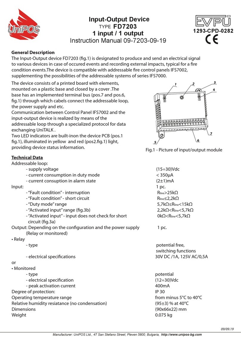
Install it according to fig.1 in the following sequence:
1.Dismantle the single output monitored module by unscrewing screws pos.7 and pos.5.
2.Installation holes and connecting wires holes are drilled on the designated places on the bottom.
3.Fix the bottom on the desired place by means of pins and screws. The connecting wires are
threaded in advance in the box.
4.Install the unit carrier to the bottom by using screws pos.5.
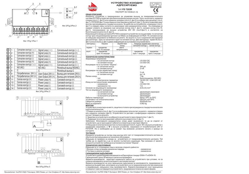
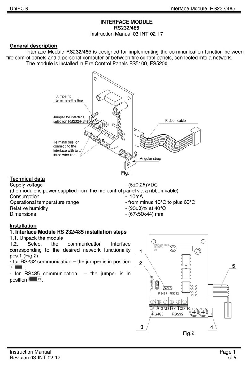
5.The electrical connection is done according to fig.3, where “A” is an external device controlled via
potential free contact and ”” -via potential contact. It is not necessary to take into consideration the
conditional beginnings and ends of the loops. It is recommended cable shoes to be used.
6.Place the cover to the bottom by using screws pos.7.
TESTING
The single output monitored module is tested after installation as a part of the site's fire alarm
system or with maintenance activities.
The output of the module is tested by the Fire Control Panel. It should be activated and the
respective indication to be on. When the menu is quitted, the single output monitored module should
be enter Duty mode.
SERVICE SCHEDULE
It is done by authorized personnel and includes the following activities:
1.Inspection for visible physical damage - monthly
2.Testing in real conditions - monthly
WARRANTY
The warrant period is 36 months from the date of sale.
The manufacturer guarantees the normal operation of the unit providing that the requirements set
herein have been observed.
The manufacturer does not bear warranty liabilities for damages caused through accidental
mechanical damage, misuse, adaptation or modification after production. The manufacturer bears
warranty liabilities for damages in the unit caused through manufacturer's fault only.
GENERAL DESCRIPTION
The single output monitored module is designed to control external devices for the fire alarm
system IFS 7000 by means of open potential free relay contact in case of detecting fire conditions.
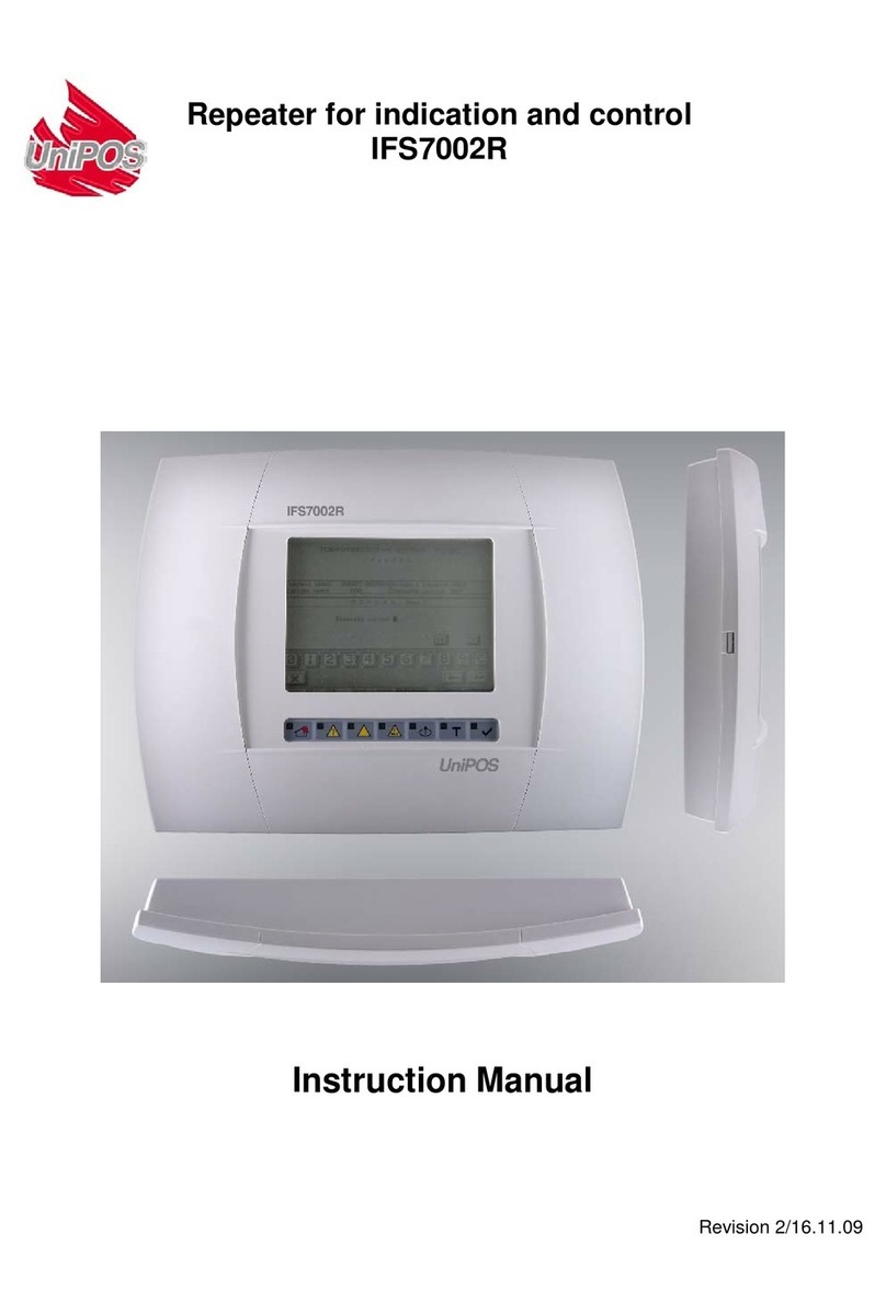
The single output monitored module (fig.1) consists of a printed circuit board (pos.2) and an unit
carrier (pos.4), fixed in a plastic box with a bottom (pos. 1) and a cover (pos.3).The terminals for
connecting the signal loop SL (pos.1), the power loop PL (pos.4), and the external devices 24V DC
(pos.3) and OUT (pos.2) are located on the printed circuit board (fig 2).
The communication between the Fire Control Panel and the single output monitored module is
completed via the signal loop by the specialized data exchange protocol UniTALK. The relay coil is
supplied by the power loop. Two built-in isolators are provided for short circuit protection -one on the
signal loop and one on the power loop.
Both LED indicators (fig.1, pos.6) provide information for the current status:
- Duty mode -red and yellow LEDsflash briefly every 16s;
- Activated output -the red LED produces continuous light, the yellow LED is not lit;
- Fault condition (activated isolator on the signal loop) - the yellow LED flashes briefly every 1s,
the red LED is not lit;
- Fault condition (activated isolator on the power loop) -the yellow LED flashes briefly every 2s,
the red LED is not lit.
TECHNICAL DATA
Supply voltage:
- signal loop (15-30)V DC
- power loop (12-30)V DC
Current consumption in Duty mode:
- signal loop 300 µÀ
- power loop 2 mA
Current consumption in Activated output:
- signal loop 3 mA
- power loop up to 1A
Relay output: 1 pc.
- type potential free, NÎ
- electrical parameters 1À/30V DC 0,5À/125V ÀC
Constant current supply output: 1 pc.
- voltage (12-30)V DC
- maximum current 1 A
Cross section of connecting wires (0,8-2,5) mm²
Type of the connecting cables:
- of the signal loop two-wire, shielded
- of the power loop two-wire
- of the external devices two-wire
Degree of protection IP 50
Operational temperature range minus 10ºÑ - plus 55ºÑ
Relative humidity resistance (92±3)% at 40ºÑ
Dimensions 120x164x74 mm
Weight 0,250 kg
1293
051-2


