POWERING TECHNOLOGY
SCIMITAR 3000 SERIES
INSTALLATION & OPERATING MANUAL
Manual No. SCIMITAR3000-1 Page 9 scimitar3000-man-rev1-0219.indd
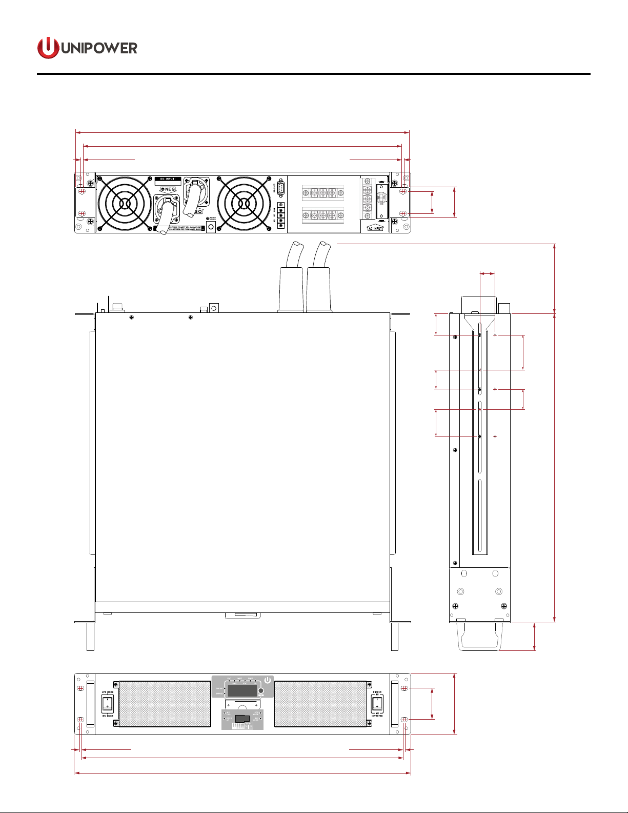
2.2.7 Frame Ground.
Connect to the frame ground of the cabinet or rack in which the unit is installed using 8AWG wire.
WARNING!
Operation of this inverter without a proper ground
connection may result in an electrical safety hazard.
2.3 Installation
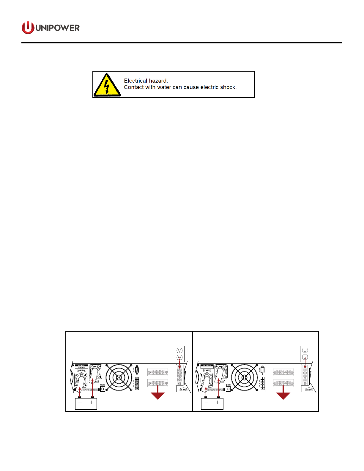
WARNING!
Shock Hazard. Before proceeding further, carefully check that
the unit is NOT connected to any batteries and that all wiring is
disconnected from any electrical sources.
Do not connect the output sockets to an incoming AC source.
This power inverter should be installed in a restricted access location such as a Telecommunications room or IT room,
whereaccessislimitedtoserviceandotherqualiedpersonnelandwhichcanonlybeenteredbyuseofatoollockor
key which is controlled by the authority that is responsible for the location. Bare parts of any terminals that present a
hazardous energy level shall be located or guarded so that unintentional bridging by conductive materials that might be
present is unlikely. A readily accessible disconnect device shall be incorporated in the building installation wiring prior to
connection to the inverter. These locations should additionally meet the following requirements:
2.3.1 Dry - Do not allow water to drip or splash on the inverter.
2.3.2 Elevated OperatingAmbient - if the inverter is installed in a closed or multi-unit rack assembly the operating
ambient temperature of the rack environment may be greater than the room ambient. consideration should
be given to installing the inverter in an environment compatible with the maximum ambient temperature of
60°C.
2.3.3 Safe-Donotinstalltheinverterinabatterycompartmentorotherareaswhereammablefumesmayexist,
such as fuel storage areas or engine compartments.
2.3.4 ReducedAirow-Installationoftheinverterinarackshouldbesuchthattheamountofairowrequiredfor
safe operation is not compromised.
2.3.5 Dust Free - Do not install the inverter in a dusty environment as dust and other particles such as wood
shavings,lingscanbepulledintotheunitwhenthecoolingfansareoperating.
2.3.6 Close to Batteries - Avoid excessive cable lengths but do not install the inverter in the same compartment
as the batteries. Use the recommended wire lengths and sizes (see section 2.6). Also, do not mount the
inverter where it will be exposed to gasses produced by the battery as these gasses are highly corrosive
and prolonged exposure will damage the inverter.
2.3.7 Mechanical Loading - Mounting of inverter in the rack should be such that a hazardous condition is not
achieved due to uneven mechanical loading.
2.3.8 Circuit Overload - Consideration should be given to the connection of the inverter to the supply circuit and
theeectthatoverloadingofthesecircuitsmighthaveonovercurrentprotectiondevicesandsupplywiring.
Appropriate consideration of equipment nameplate ratings should be used when addressing this concern.
2.3.9 Reliable Earthing - Reliable earthing of rack-mounted equipment should be maintained. Particular attention
should be given to supply connections other than direct connections to the branch circuit (e.g. use of power
strips).