Unitekno C500 User manual


ITALIANO
1
PRIMA DELL’USO
Prima di usare l’apparecchio, leggere attentamente le informazioni contenute in questo manuale. Queste riguardano
l’installazione, l’uso e la manutenzione dell’apparecchio. Conservare questo libretto in un luogo sicuro ed appropriato
e consegnarlo ad un eventuale successivo proprietario dell’apparecchio stesso.
Questo apparecchio è costruito per soddisfare gli standard di sicurezza stabiliti dalle norme in vigore per gli apparec-
chi elettrici. In particolare soddisfa le prescrizioni delle norme della 2014/30/UE (Compatibilità Elettromagnetica) e
2014/35/UE (Direttiva Bassa Tensione). Esso è pertanto contrassegnato dal marchio CE.
Il produttore si riserva il diritto di apportare qualunque modifica senza preavviso.
In caso di smarrimento è possibile consultare e/o scaricare questo manuale dal sito www.unitekno.com
AVVERTENZE GENERALI PER LA SICUREZZA
Non utilizzare l’apparecchio se questo presenta segni di danneggiamento (incrinature, fratture) se il cavo di alimen-
tazione è danneggiato, se si sospetta possa esserci un qualche tipo di difetto interno (ad esempio l’apparecchio è
caduto) e se si notano delle perdite.
Nel caso il cavo di alimentazione fosse danneggiato questo deve essere sostituito da un centro assistenza autorizza-
to dal costruttore in quanto occorre un utensile speciale per accedere ad esso.
Verificare la targa dati posta sotto al prodotto e controllare che la tensione di alimentazione e l’assorbimento siano
adeguati alla capacità dell’impianto.
Collegare l’apparecchio ad una presa provvista di connessione di terra.
Durante lo spostamento dell’apparecchio evitare di mettere in trazione il cavo di alimentazione.
Scollegare l’apparecchio agendo sulla presa e non sul cavo. Agendo sul cavo questo potrebbe danneggiarsi.
Disinserire la spina di alimentazione dalla presa di corrente dopo l’uso.
Non lasciare l’apparecchio incustodito mentre è collegato alla presa di rete.
Non permettere l’uso dell’apparecchio a bambini con meno di 8 anni o a persone incapaci.
Non collegare alla presa dell’apparecchio apparati aventi assorbimento superiore a quello indicato! Collegare all’ap-
parecchio solo accessori originali la cui compatibilità è garantita dal costruttore.
L’apparecchio è costruito per essere usato in locali chiusi (al coperto).
Non immergere l’apparecchio in acqua!
Non aprire il tappo della caldaia quando questa è in pressione.
Non puntare il getto di vapore verso persone o altri esseri viventi. Questo apparecchio produce vapore ad elevata
temperatura. Evitare il contatto diretto con la pelle. Pericolo di scottature.
Non utilizzare l’apparecchio per pulire altri apparecchi elettrici.
Durante la pulizia il vapore non deve essere diretto nell’interno dei forni
Non immettere nella caldaia o nel serbatoio di recupero alcun tipo di sostanza (detergente o altro) se non specifica-
mente approvata dal produttore.
Prima di utilizzare l’apparecchio per pulire superfici che potrebbero essere danneggiate, ad esempio fibre sintetiche,
materiali plastici, legno, verificate se queste possono sopportare alte temperature provando prima la pulizia su parti
nascoste ed osservando le istruzioni fornite dai produttori.
Utilizzare ricambi originali per le eventuali riparazioni. Rivolgersi a centri assistenza autorizzati.
A questo apparecchio possono essere collegati accessori per la pulizia e la stiratura.
Possono essere collegati anche accessori per pulizia motorizzati per apparecchi per la pulizia ad aspirazione d’acqua.
Riferirsi alle specifiche istruzioni.
L’orifizio di riempimento non deve essere aperto durante l’utilizzo.

2
ITALIANO
PRENDERE FAMILIARITÀ CON L’APPARECCHIO, LE SUE PARTI, I COMANDI
> Corpo Macchina
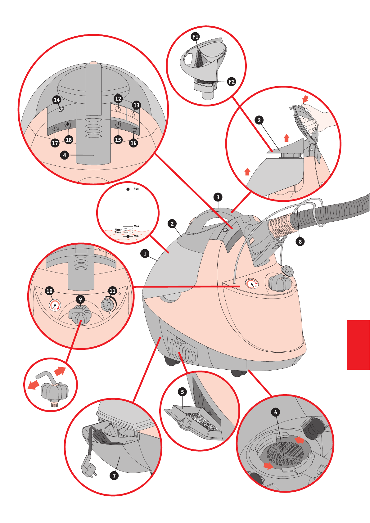
SERBATOIO DI RECUPERO
È il serbatoio nel quale viene recuperato lo sporco. Deve es-
sere inserita in esso una certa quantità d’acqua (tra il livello
Min e il livello Max) che agisce da ltro. Quando l’acqua è
sporca va sostituita. L’azione ltrante è migliore se l’acqua
all’interno del serbatoio è pulita.
CESTELLO DI FILTRAGGIO
Posto sopra al serbatoio, garantisce l’azione di ltraggio.
È composto da un supporto in plastica, una rete cilindrica
metallica all’interno della quale scorre un galleggiante ed è
dotato di due ltri in poliestere (F1 e F2). Va tenuto sempre
pulito ed asciugato accuratamente prima di avviare l’aspi-
razione. Non usare l’apparecchio senza i ltri in poliestere
posti sul cestello di ltraggio!
COPERCHIO SERBATOIO
Si apre premendo sul pulsante del manico, permette di ac-
cedere al cestello e al serbatoio di recupero per inserire l’ac-
qua di ltraggio ed effettuare le normali operazioni di pulizia.
Quando è chiuso il manico consente di trasportare agevol-
mente l’apparecchio. Non spingere il pulsante di apertura
mentre si solleva l’apparecchio!
PRESA ASPIRAZIONE-VAPORE
Protetta da uno sportellino che si apre agendo sull’apposito
incavo, la presa permette di collegare alla unità i dispositivi
di pulizia e stiratura. E’ dotata di contatti elettrici, una con-
nessione vapore, un condotto aspirazione.
COPERCHIO FILTRO LATERALE
Il ltro laterale in materiale antistatico, è il dispositivo at-
traverso il quale l’aria, già ltrata dall’acqua, viene espulsa
nell’ambiente. Occorre vericare periodicamente lo stato del
ltro e sostituirlo all’occorrenza. Un ltro sporco o danneg-
giato non garantisce una corretta pulizia e può diminuire la
potenza aspirante dell’apparecchio. Per accedere al ltro
basta aprire lo sportellino laterale nel quale è collocato.
COPERCHIO FILTRO INFERIORE
Il ltro inferiore, posto in una sede sotto all’apparecchio,
serve ad evitare che polveri in sospensione nell’ambiente,
niscano nei condotti di raffreddamento del motore. Questo
ltro non agisce nel circuito della pulizia. Occorre periodi-
camente vericarne lo stato e, all’occorrenza, pulirlo. Può
essere lavato con acqua. Asciugare prima di rimettere nella
sua sede. Per accedere al ltro basta ruotare il coperchio
nel senso indicato dalle frecce. Tenendo pulito il ltro inferio-
re, si migliorano le prestazioni del motore e si prevengono
malfunzionamenti.
CASSETTO PORTA CAVO ALIMENTAZIONE
Posto sotto al serbatoio di recupero, si apre tirando dalla
apposita ansa, serve a riporre il cavo di alimentazione dopo
l’uso. La stessa ansa consente di chiudere il cassetto con il
cavo di alimentazione estratto.
ANTENNA
È costituita da un lo di acciaio inossidabile ed è ssata
all’apparecchio tramite due fori. La sua funzione è quella di
sopportare parte del peso del essibile, alleggerendo il lavo-
ro durante le operazioni di pulizia. Porre il essibile sopra la
apposita sede della antenna come in gura. L’antenna può
essere rimossa per riporre l’apparecchio.
TAPPO VALVOLA
È il dispositivo di chiusura della caldaia. Contiene anche una
valvola di sicurezza. Prima di aprirlo sollevare la leva per
fare uscire l’eventuale vapore residuo. Dopo averlo serrato
abbassare la leva.
MANOMETRO
È un dispositivo che indica lo stato della pressione della cal-
daia. Il suo funzionamento è indipendente dalla alimentazio-
ne elettrica della macchina.
MANOPOLA DI REGOLAZIONE DEL VAPORE
Permette di regolare la quantità di vapore in uscita.
INTERRUTTORE ACCENSIONE GENERALE
INTERRUTTORE CALDAIA
PULSANTE ACCENSIONE MOTORE
Premendolo si attiva l’aspirazione. Ad ogni pressione viene
variata la potenza aspirante. Tenendo premuto il pulsante
per qualche secondo il motore si spegne.
SEGNALATORE ACCENSIONE GENERALE
SEGNALATORE ACCENSIONE CALDAIA
SEGNALATORE VAPORE PRONTO
Si accende quando la caldaia ha raggiunto la pressione di
esercizio, circa 4,5 bar. Attendere che il segnalatore si ac-
cenda prima di cominciare ad utilizzare il vapore. Successi-
vamente trascurare lo stato della spia.
SEGNALATORE VUOTO
Si accende quando manca acqua in caldaia.
In corrispondenza si avverte un segnale acustico (buzzer).
Quando si accende occorre provvedere a riempire la cal-
daia.
1
2
3
4
5
6
7
8
9
10
11
12
13
14
15
16
17
18

3
ITALIANO

4
ITALIANO
PRENDERE FAMILIARITÀ CON L’APPARECCHIO, LE SUE PARTI, I COMANDI
> Kit pulizia vapore aspirazione
IMPUGNATURA VAPORE-ASPIRAZIONE
È costituita da un connettore, un tubo essibile, una impu-
gnatura vera e propria. Il connettore va inserito nella ap-
posita presa dell’apparecchio (4). Per rimuoverlo agire sui
ganci esterni (D). Sulla parte che si impugna si trovano il
comando per l’azionamento del motore (A) ed il grilletto per
l’erogazione del vapore (B). Ad essa si possono collegare
i terminali di pulizia tramite l’apposito attacco a baionetta.
Per scollegare gli accessori è sufciente tirarli dalla apposita
ghiera. L’impugnatura è dotata di un blocco della erogazione
del vapore (C). Quando il blocco è inserito l’erogazione del
vapore non è possibile.
TUBI PROLUNGA
Si collegano alla impugnatura e permettono di collegare
alla loro estremità i terminali di pulizia. Sono di lunghezze
diverse per garantire la massima praticità nelle diverse uti-
lizzazioni.
SPAZZOLA PAVIMENTI
Si collega alla impugnatura o ai tubi prolunga. La spazzola
è costituita da un corpo centrale a forma di H, uno snodo
verticale comandato da un tastone (E) uno snodo orizzon-
tale con relativo tasto di blocco (F), due pinze montate su
slitte mobili (G).
Il corpo ad H è costituito da due pattini. Su uno di essi è po-
sizionata l’erogazione del vapore e una la di setole, sull’al-
tro l’aspirazione.
Premendo sul tastone (E) è possibile effettuare una rotazio-
ne di 180° sull’asse verticale e mettere la parte aspirazione
o la parte erogazione vapore alternativamente in posizione
anteriore. Agendo sul blocco (F) (scorrimento in avanti) il
connettore della spazzola ruota sull’asse orizzontale. Le
slitte mobili su cui sono montate le pinze possono essere
abbassate (posizione esterna) o rialzate (posizione interna).
SPAZZOLA TESSUTI
Si collega alla impugnatura o ai tubi prolunga. E’ costitu-
ita da un corpo principale e da una piastra mobile su cui
è montata una setola.E’ dotata di uno snodo che si aziona
premendo l’apposito tasto (F).
LANCIA
Si collega alla impugnatura o ai tubi prolunga. E’ costituita
da un supporto principale sul quale è posto l’erogatore del
vapore e da una bocchetta di aspirazione mobile. Mettendo
la bocchetta in posizione retratta, è possibile collegare alla
lancia gli spazzolini rotondi.
SPAZZOLINI ROTONDI
Si collegano all’erogatore di vapore della lancia inlandoli a
pressione. Per rimuoverli è sufciente tirarli.
BOCCHETTA TRASPARENTE
Si collega allo stesso supporto della lancia e può essere
usata in combinazione con lo spazzolino a lama.
TERGIVETRO
Si collega all’impugnatura o ai tubi prolunga. E’ dotato di
fori per l’erogazione del vapore e di una lama in gomma
raschia-sporco.
PIASTRA TAPPETI
Si inserisce alla base della spazzola pavimenti. Le ruote
hanno 2 posizioni per adattarsi ai diversi tipi di tappeti.
Per regolare l’altezza premere i tasti L.
> Kit optional
All’apparecchio possono essere collegati altri kit per la puli-
zia e la stiratura. Riferirsi alle speciche istruzioni.
19
20
21
22
23
24
25
26
27

5
ITALIANO

6
ITALIANO
USO
> Come usare l’apparecchio
Una guida passo passo per imparare ad usare l’apparecchio
PASSO 1
IMMETTERE ACQUA NEL SERBATOIO FREDDO
Ad apparecchio scollegato dalla rete elettrica, sollevare la leva del tappo valvola (9), fare uscire eventuale vapore residuo, svitare il
tappo, introdurre acqua (massimo 2,5litri). Richiudere il tappo ed abbassare la leva.
PASSO 2
IMMETTERE ACQUA PER FILTRO
Aprire il coperchio serbatoio (3).
Estrarre il serbatoio (1) ed il cestello (2).
Immettere acqua no al livello (tra Min e Max) indicato nel serbatoio.
Non accendere l’aspiratore senza aver inserito acqua nel serbatoio di recupero. Non inserire più acqua del livello indicato.
PASSO 3
ACCENDERE
Estrarre il cavo di alimentazione dall’apposito cassetto (7). Collegare l’apparecchio ad una presa di corrente.
Accendere l’interruttore generale (12). Si accende l’indicatore luminoso (15) che indica che l’apparecchio è acceso. Accendere l’in-
terruttore caldaia (13). Si accende l’indicatore luminoso (16) che indica che la caldaia è in riscaldamento. L’accensione del solo
interruttore caldaia non consente l’utilizzo dell’apparecchio poichè le funzioni di erogazione del vapore sono abilitate dall’interruttore
generale. Quando l’indicatore luminoso che indica vapore pronto (17) si accende vuol dire che l’apparecchio ha raggiunto la pres-
sione di esercizio. Dopo la prima accensione la spia del vapore pronto si accende e si spegne varie volte durante l’uso. Trascurare le
successive accensioni.
PASSO 4
COLLEGARE IMPUGNATURA ED ACCESSORI
Collegare l’impugnatura vapore aspirazione (19) alla apposita presa (4). Collegare all’impugnatura l’accessorio desiderato.
PASSO 5
ATTIVAZIONE ASPIRAZIONE ED EROGAZIONE DEL VAPORE
Con il pulsante (A) nella parte superiore dell’impugnatura si attiva l’aspirazione. Ad ogni pressione viene variata la potenza aspirante.
Tenendo premuto il pulsante per qualche secondo il motore si spegne.
Con il grilletto (B) posto nella parte inferiore si eroga vapore. E’ possibile variare la quantità di vapore erogato agendo sulla apposita
manopola (11).
PASSO 6
RICAMBIO ACQUA - FILTRO
Buttare via periodicamente l’acqua sporca e sostituirla con acqua pulita. L’azione ltrante è migliore quando l’acqua nel serbatoio di
recupero è pulita. La trasparenza del serbatoio permette di vericare lo stato dell’acqua-ltro.
PASSO 7
MANCANZA D’ACQUA IN CALDAIA
Se durante l’uso si accende il segnalatore di vuoto (18) e si sente il corrispondente segnale acustico, provvedere a riempire la caldaia
come al passo 1. Non è necessario attendere che la pressione in caldaia scenda, sollevando la leva del tappo si fa uscire il vapore
residuo e si può procedere al riempimento.
USO SOLO ASPIRAZIONE
L’apparecchio può essere utilizzato come aspirapolvere a ltraggio ad acqua. In questo caso non è necessario accendere la caldaia.

7
ITALIANO
> Uso degli accessori e possibili impieghi
LA SPAZZOLA PAVIMENTI
Può essere utilizzata per la pulizia di tutti i pavimenti, sia nella funzione solo vapore, che vapore-
aspirazione. Può essere utilizzata per ampie vetrate e specchi. Con la setola in posizione anteriore
permette di sciogliere lo sporco anche sugli angoli dei battiscopa.
Con le pinze abbassate ed un panno ssato a queste può essere usata su parquet, legno, marmo,
anche per rimuovere o passare la cera. Può essere usata in funzione di aspira-liquidi per rimuovere
liquidi accidentalmente caduti a terra.
LA PIASTRA TAPPETI
Può essere utilizzata per pulire tappeti, moquette. Le ruote agevolano lo scorrimento.
LA SPAZZOLA TESSUTI
Può essere utilizzata su tutti i tipi di tappezzeria (tende, divani, poltrone, materassi).
La piastra con setola permette di abbinare una azione di spazzolatura.
IL TERGIVETRO
Può essere utilizzato per la pulizia di vetri, nestre, vetrate e specchi. Spruzzare il vapore per inumi-
dire la supercie, passare con la gomma raschiavetro. L’aspirazione rimuoverà il vapore e lo sporco
disciolto
LA LANCIA
Può essere usata per pulire lavelli, bagni, cucine, suppellettili, per rimuovere lo sporco dai battiscopa,
dai termosifoni, sulle tapparelle ed in tutti i casi nei quali è opportuno utilizzare un terminale di piccole
dimensioni. La parte aspirazione della lancia può essere retratta quando non si usa l’aspirazione.
Possono così essere collegati alla lancia spazzolini di vario tipo. La bocchetta trasparente è l’ideale
per la pulizia delle piccole superci e dei vetri all’inglese.

ITALIANO
8
PULIZIA E MANUTENZIONE
PULIZIA DELL’APPARECCHIO
Dopo ogni uso è opportuno riporre l’apparecchio pulito ed asciutto.
Il cestello di ltraggio ed il serbatoio di recupero possono essere lavati in lavastoviglie.
Rimuovere i ltri prima del lavaggio.
Pulire la supercie esterna dell’apparecchio con un panno umido.
Non usare detergenti o panni sgocciolanti
FILTRI ESTERNI
I ltri in poliestere del cestello di ltraggio vanno puliti ed asciugati dopo ogni uso.
Controllare periodicamente il ltro inferiore, se necessario provvedere alla sua pulizia che può essere effettuata con acqua fredda.
Asciugare prima di rimettere al suo posto.
Vericare periodicamente il ltro HEPA (ltro laterale) e provvedere, se del caso, alla sostituzione.
Mantenere puliti i ltri in poliestere (ltro inferiore, ltro cestello).
DECALCIFICAZIONE DELLA CALDAIA
I sali minerali disciolti nell’acqua ed in modo particolare il calcio si depositano nella caldaia. Questo, col tempo, può generare problemi
di funzionamento (tempi di riscaldamento più lunghi, maggior consumo energetico, otturazione di alcuni condotti). Per prevenire questi
problemi è necessario provvedere periodicamente alla decalcicazione della caldaia. Dopo aver svuotato completamente la caldaia,
inserire 1/2 bicchiere di aceto di vino bianco. Inserire 1/2 litro d’acqua. Chiudere il tappo ed accendere l’apparecchio. Attendere che
si accenda il segnalatore luminoso “vapore pronto”. A questo punto spegnere l’apparecchio, attendere che la pressione in caldaia
diminuisca (no a quando il manometro tornerà al minimo), svuotare la caldaia e sciacquare con abbondante acqua.
Non collegare accessori nè azionare l’erogazione del vapore nella fase di decalcicazione!
Per ottenere le massime prestazioni dal proprio apparecchio ed evitare inutili sprechi di energia elettrica, è necessario attenersi ad
alcune semplici indicazioni. Non accendere la caldaia se si intende usare solo la funzione aspirazione.
Provvedere periodicamente alla pulizia (decalcicazione) della caldaia. I residui che si depositano sull’elemento riscaldante, ne limita-
no l’efcienza. Provvedere alla manutenzione (pulizia e ricambio) dei ltri.
L’apparecchio non si accende
Vericare che l’apparecchio sia collegato ad una presa di corrente.
Vericare che la presa a cui è collegato l’apparecchio sia alimentata.
Vericare che l’interruttore generale sia acceso.
L’apparecchio non eroga vapore
Vericare che entrambi gli interruttori siano accesi.
Vericare attraverso il manometro che ci sia pressione.
Vericare che la manopola della regolazione non sia al minimo
Vericare lo stato della spia vapore pronto.
Vericare che l’impugnatura vapore-aspirazione sia ben collegata.
Vericare che non sia inserito il blocco della erogazione del vapore (C) sulla impugnatura.
Vericare che non vi siano occlusioni nell’accessorio che state utilizzando.
Dall’accessorio esce acqua anziché vapore
Provvedere a svuotare la caldaia completamente e riempirla con 2,5l max di acqua.
Il galleggiante non chiude a livello “full” ed esce acqua dai filtri
Vericare che il galleggiante non sia bloccato nella sua corsa nella rete cilindrica metallica.
Vericare che i ltri in poliestere F1 ed F2 siano stati posti correttamente nel cestello (2).
Provvedete a gettare gli imballaggi e i ltri usati, attenendovi alle norme vigenti. Se vi sono disposizioni particolari nella vostra area per
il riciclaggio dei materiali (raccolta differenziata) attenetevi alle indicazioni fornite da queste.
Questo prodotto è conforme alla Direttiva EU 2012/19/UE. Il simbolo del cestino barrato riportato riportato sull’apparecchio indica
che il prodotto, alla ne della propria vita utile, deve essere trattato separatamente dai riuti domestici. L’utente è responsabile del
conferimento dell’apparecchio, a ne vita, alle appropriate strutture di raccolta. L’adeguata raccolta differenziata per l’avvio succes-
sivo dell’apparecchio dismesso al riciclaggio, al trattamento e allo smaltimento ambientalemente compatibile, contribuisce ad evitare
possibili effetti negativi sull’ambiente e sulla salute e favorisce il riciclo dei materiali di cui è composto il prodotto. Per informazioni più
dettagliate inerenti i sistemi di raccolta disponibili, rivolgersi al servizio locale di smaltimento riuti, o al negozio in cui è stato effettuato
l’acquisto.
SUGGERIMENTI PER IL RISPARMIO ENERGETICO
RISOLUZIONE POSSIBILI PROBLEMI
ISTRUZIONI PER LA DISMISSIONE E NORME DI TUTELA AMBIENTALE

ENGLISH
9
BEFORE USE
Before using the machine for the first time, please read the information contained in this booklet carefully and com-
pletely. It explains how to install, use, and maintain the machine. Please keep this manual in a safe place and pass
it along to any future owners of the machine.
This product has been manufactured to comply with all current safety standards for electrical devices. More speci-
fically, it complies with EU standards 2014/30/EU(Electromagnetic Compatibility) and 2014/35/EU(Low Voltage
Directive), and therefore, it bears the EC mark.
The manufacturer reserves the right to make any type of modification without advanced notice.
If you lose you can view and / or download this manual from the website www.unitekno.com
GENERAL SAFETY PRECAUTIONS
Do not use this machine if there are signs of damage (cracks, breaks), if the power cord is damaged, or if you suspect
that there may be an internal defect (for example, after the machine has fallen) and if you see any leaks.
If the power cord is damaged, a manufacturer-authorised service centre must replace it since a special tool is needed
to access it.
Read the rating-plate located under the machine; make sure the voltage and input ratings comply with the system’s
capacity.
Plug the machine into a grounded outlet.
While moving the machine, avoid tugging on the power cord.
Disconnect the machine from the electrical power source by pulling the plug. Do not disconnect it by pulling on the
cord, since this could damage the machine. Remove the power supply plug from the socket after use.
Do not leave the machine unattended while it is plugged in.
Do not let children under 8 years or other incompetent persons use the machine.
Do not attach devices that exceed the indicated input rating to the machine!
Only use the machine’s original accessories, which are guaranteed compatible by the manufacturer.
This machine has been manufactured for use in enclosed (covered) areas.
Do not submerge the machine in water!
Do not open the boiler valve cap while under pressure.
Do not point the steam jet at persons or other living beings. This machine produces high-temperature steam. Avoid
direct contact with the skin. Burns warning.
Do not use the machine to clean other electrical devices.
The steam must not be aimed inside the ovens during cleaning.
Do not place any type of substance (detergents or anything else) in the boiler or in the backwater tank if not speci-
fically approved by the manufacturer.
Before using the machine to clean surfaces that may get damaged (e.g. synthetic fibres, plastics, wood, etc.), check
their capacity to withstand high temperatures by doing a trial run on a hidden area and by carefully following manu-
facturer’s instructions.
Only use original replacement parts for any necessary repairs. Please see an authorised service centre.
Cleaning and ironing accessories can be connected to this appliance.
Motorised accessories for water suction cleaning appliances can also be connected.
Refer to specified instructions.
The filling aperture must not be open during use.

10
ENGLISH
MACHINE PARTS AND CONTROLS
> Machine Body
BACKWATER TANK
The backwater tank collects dirty water. It must contain a
specic quantity of water (between Min and Max), which
acts as a lter. Once the water is dirty, it must be changed,
since it lters better when it is clean.
FILTER BASKET
Located above the tank, the basket ensures proper ltering.
It is composed of a plastic base and a cylinder-shaped me-
tal wire net containing a oat gauge, and is equipped with
two polyester lters (F1 and F2). The lter basket must
always be kept clean, and it must be carefully dried befo-
re the vacuum function is activated. Do not use the ma-
chine if the polyester lters are not inserted in the lter ba-
sket!
TANK COVER
The tank cover opens by pressing the handle button. It pro-
vides access to the lter basket and the backwater tank to
pour in the lter water and perform regular cleaning ope-
rations. When closed, the handle allows you to carry the
machine easily. Do not press the open button while lifting up
the machine!
SUCTION/STEAM SOCKET
The suction/steam socket is protected by a small door,
which can be opened by pulling up on the notch. Cleaning
and ironing devices can be connected to the socket. It is
equipped with electric contacts, a steam connection, and a
suction tube.
SIDE FILTER COVER
The side lter, which is manufactured in antistatic material,
releases water-ltered air into the environment. You should
periodically check the lter and replace it when necessary. A
damaged or dirty lter makes cleaning more difcult and can
reduce the suction power of the machine. To access the l-
ter, simply open the side door where it is located.
BOTTOM FILTER COVER
The bottom lter, located on the underside of the machine,
prevents dust from entering the motor’s cooling ducts. This
lter is not part of the cleaning circuit. Check it periodically
and clean it with water when necessary. Dry the lter before
putting it back in place. To access the lter, simply rotate
the cover in the direction indicated by the arrows. When the
bottom lter is kept clean, the motor performs better, preven-
ting malfunctions.
POWER CORD COMPARTMENT
Located beneath the backwater tank, the power cord com-
partment can be opened by pulling from the notch. It is used
to store the power cord tidily in between uses. The notch
allows you to close the compartment even while the power
cord is extracted.
ANTENNA
The antenna, which is manufactured in stainless steel wire
and inserted into the two holes on the machine, supports
part of the weight of the exible hose, helping to lighten work
during cleaning. Place the exible hose on the antenna as
shown in the gure. It can be removed before putting the
machine away.
VALVE CAP
The cap, which is used to close off the boiler, includes a sa-
fety valve. Before opening it, lift the lever to let any residual
steam escape. Once you have screwed it tightly into place
again, lower the lever.
PRESSURE GAUGE
The gauge indicates the boiler pressure. It functions whe-
ther the machine is plugged in or not.
STEAM REGULATION KNOB
Regulates the amount of steam output by the machi-
ne.
MAIN ON/OFF BUTTON
BOILER ON/OFF BUTTON
MOTOR ON/OFF BUTTON
Press the button to activate the suction function. Each time
you press it, the suction power changes. Hold down the
button for a few seconds to shut off the motor.
MAIN POWER INDICATOR
BOILER ACTIVATION INDICATOR
STEAM READY INDICATOR
This indicator lights up once the boiler has reached opera-
ting pressure, which is approximately 4.5 bar. Wait for it to
light up before using the steam function. Once it has lit up
the rst time, you can ignore the indicator status throughout
the rest of operation.
EMPTY BOILER INDICATOR
This indicator lights up when the boiler has run out of water.
An acoustic signal (buzzer) will also go off. When it goes on,
you need to ll the boiler.
8
9
10
11
12
13
14
15
16
17
18
1
2
3
4
5
6
7

11
ENGLISH

12
MACHINE PARTS AND CONTROLS
> Steam/suction cleaning kit
STEAM/SUCTION HANDLE UNIT
The unit consists of a connector, a exible tube and a
handgrip. The connector is inserted in the suction/steam
socket (4). To remove it, press the external clips (D). The
handle contains the on/off button for the motor (A) and the
steam trigger (B). The various cleaning accessories can be
attached to the handle at the provided bayonet base. To
remove them, simply pull them off the ring. The handle also
has a steam blocking switch (C). When this switch is on,
steam cannot pass.
EXTENSION TUBES
The extension tubes are connected to the handle and can
be attached to the various cleaning accessories. They have
different lengths to guarantee maximum practicality in their
different uses.
FLOOR BRUSH
The oor brush attaches to the handle or extension tubes. It
consists of a central H-shaped body, a vertical joint control-
led by a button (E), a horizontal joint with a locking button
(F), and two clips mounted on slides (G).
The H-shaped body is two-piece. It features a steam outlet
piece with a row of bristles and a suction intake piece.
Press the button (E), to rotate the head 180° on a vertical
axis and place the suction piece or the steam outlet piece in
the forward position. Press the locking button (F) (pushing
forward) to rotate the oor brush connector on a horizontal
axis. The slides on which the clips are mounted can be lo-
wered (outside position) or raised (inside position).
FABRIC BRUSH
The fabric brush can be attached to the handle or the exten-
sion tubes. It consists of a central body and a moveable
plate containing a brush. It is equipped with a joint that can
be moved by pressing the button (F).
NOZZLE
The nozzle can be connected to the handle or the exten-
sion tubes. It consists of the main body, which contains the
steam outlet, and a moveable suction opening. By moving
the suction opening to the back position, you can attach the
round brushes to the nozzle.
ROUND BRUSHES
Round brushes can be inserted into the nozzle steam outlet
by using a little pressure. To remove them, simply pull them
out.
TRANSPARENT NOZZLE
It is connected to the same support as the water-jet pipe and
may be used with the brush.
GLASS WIPER
The glass wiper can be attached to the handle or the exten-
sion tubes. It is equipped with steam holes and a dirt-scra-
ping rubber blade.
CARPET PLATE
It is inserted at the base of the oor brush. The wheels have
2 positions to adapt to different types of carpets. Press the L
keys to adjust height.
> Optional kit
Additional cleaning and ironing kits can be attached to the
machine. Please refer to the specic instructions.
19
20
21
22
23
24
25
ENGLISH
26
27

13
ENGLISH

14
USE
> How to use the machine
A step-by-step guide to learning how to use the machine
STEP 1
POURING WATER IN THE BOILER
With the machine unplugged from the electrical outlet, raise the lever on the valve cap (9), let any residual steam escape, unscrew the
cap, and pour in the water (maximum 2.5 litres). Screw on the cap and lower the lever.
STEP 2
POURING FILTER WATER IN THE BACKWATER TANK
Open the tank cover (3).
Take out the tank (1) and the lter basket (2).
Pour water in up to the level (between Min and Max) indicated on the tank.
Do not activate the suction function if you have not rst poured water into the backwater tank.
Do not exceed the indicated water level.
STEP 3
TURNING THE POWER ON
Remove the power cord from its compartment (7). Plug it into an electrical outlet.
Press the main on/off button (12). The indicator light goes on (15) indicating that the device is on.
Press the boiler on/off button (13). The indicator light goes on (16) indicating that the boiler is warming up. If you turn on the boiler on/
off button by itself, the machine will not be ready for use because the steam functions are only activated when the main on/off button
has been switched to on. When the “steam ready” indicator light comes on (17), it means that the machine has reached its operating
pressure. Once the indicator has been turned on, the light will continue to go on and off throughout use. There is no need to pay
attention to it.
STEP 4
ATTACHING THE HANDLE AND ACCESSORIES
Attach the steam/suction handle (19) to the socket (4). Attach the desired accessory to the handle.
STEP 5
ACTIVATING THE SUCTION AND STEAM FUNCTIONS
Activate the suction function by pressing the button (A) on the upper part of the handle. Each time the button is pressed, the suction
power changes. If you hold the button down for a few seconds, the motor shuts off.
Press the trigger (B) on the lower part of the handle to activate the steam. You can adjust the amount of steam by turning the knob (11).
STEP 6
CHANGING THE FILTER WATER
Periodically, throw away the dirty water and replace it with clean water. When the water in the backwater tank is clean, it lters better.
The tank is transparent so you can check whether the lter water is clean or dirty.
STEP 7
LACK OF WATER IN THE BOILER
If the empty water indicator (18) turns on while you’re using the machine and you hear the accompanying acoustic signal, ll the boiler
as indicated in step 1. You do not need to wait for the boiler pressure to decrease. Simply lift the valve cap lever to let the residual
steam escape and then proceed to lling the tank.
USING THE SUCTION FUNCTION ALONE
The machine can be used as a water-ltered vacuum cleaner.
In this case, you do not need to turn on the boiler.
ENGLISH

15
> Where and how to use the accessories
FLOOR BRUSH
The oor brush accessory can be used to clean all types of oors, either with steam alone or combined
steam/suction. It can also be used for large glass and mirrored surfaces. When the bristle piece is
in the forward position, you can even dissolve the dirt found on the corners of the skirting board. You
can attach a cloth to the clips and use it on parquet ooring, wood, marble, and even to remove or put
down wax. You can use the liquid suction function to clean up liquids accidentally spilled on the oor.
THE CARPET PLATE
It can be used to clean mats and carpets. The wheels make running easier.
FABRIC BRUSH
The fabric brush accessory can be used on all types of upholstery (curtains, sofas, armchairs, mattres-
ses). The bristle plate provides additional scrubbing action.
GLASS WIPER
The glass wiper accessory can be used to clean glass, windows, and mirrors. Spray the steam to
dampen the surface and then go over it with the rubber glass-scraping blade. The suction function
removes the steam and loosened dirt.
NOZZLE
The nozzle accessory can be used to clean sinks, bathrooms, kitchens, and furnishings, to remove dirt
from skirting boards, radiators, roller shutters and in all those places where the job requires a small
cleaning head. The suction part of the nozzle can be retracted when it is not needed. This allows you
to attach various types of small brushes to the nozzle. The transparent nozzle is ideal for cleaning
small surfaces and English-style windows.
ENGLISH

16
CLEANING AND CARE
CLEANING THE MACHINE
Each time you use the machine, you should clean and dry it before putting it away.
The lter basket and the backwater tank can be cleaned in the dishwasher.
Remove the lters before washing.
Clean the outside surface of the machine with a damp cloth.
Do not use detergents or dripping wet cloths.
EXTERNAL FILTERS
The polyester lters of the lter basket should be cleaned and dried after every use.
Periodically, check the bottom lter. If necessary, clean it with cold water. Dry it before putting it back in place.
Periodically, check the HEPA (side lter) and, if necessary, replace it.
Keep the polyester lters clean (bottom lter, lter basket).
DECALCIFYING THE BOILER
Minerals dissolved in your local water, and especially calcium, can build up in the boiler. Over time, this build-up can cause problems
(longer warm-up times, greater energy costs, tube clogging). To prevent these problems, you should periodically decalcify the boiler.
Completely empty the boiler and pour in 1/2 a glass of white wine vinegar. Then, pour in 1/2 a litre of water. Screw the valve cap in
place and turn the machine on. Wait until the “steam ready” indicator comes on and then turn the machine off. At this point, switch the
appliance off, wait for the pressure in the boiler to decrease (until the manometer goes back to minimum), empty the boiler and rinse
out thoroughly with plenty of water. Do not attach any accessories or activate the steam button during decalcication!
To get the best performance out of your machine and avoid unnecessary energy waste, please follow the indications provided below.
Do not turn the boiler on if you are only going to use the suction function. Periodically clean (decalcify) the boiler. Mineral build-up on
the heating element limits its efciency. See to proper lter maintenance (cleaning and replacement).
To get the best performance out of your machine and avoid unnecessary energy waste, please follow the indications provided below.
Do not turn the boiler on if you are only going to use the suction function.
Periodically clean (decalcify) the boiler. Mineral build-up on the heating element limits its efciency.
See to proper lter maintenance (cleaning and replacement).
The machine does not turn on
Check that the machine is plugged in.
Check that the power outlet is functioning.
Check that the main on/off button is on.
The machine does not produce steam
Check that both the main and boiler on/off buttons are on.
Check the gauge to see if there is pressure.
Check that the regulation knob is not on minimum
Check the status of the “steam ready” indicator.
Check that the steam/suction handle is properly attached.
Check that the steam blocker (C) on the handle is not activated.
Check that there are no blockages in the accessory you are using.
The accessory produces water rather than steam
Empty the boiler completely and ll it with a maximum of 2.5 litres of water.
The float gauge does not close when it hits “full” and water leaks from the filters
Check that the oat gauge is not blocked during its movement through the cylinder-shaped metal wire net.
Check that the F1 and F2 polyester lters have been properly positioned in the basket (2).
Dispose of packaging and used filters in accordance with current standards. Follow the instructions for any material recycling (segre-
gated collection) in your area. This product conforms to the 2012/19/EU Directive. The symbol of a crossed out basket on the devi-
ce specifies that the product should be disposed of separately from domestic waste at the end of its useful life. The user is
responsible for taking the expired device to an appropriate collection point. Suitable segregated collection for ensuing recycling,
treatment and environmentally compatible disposal helps prevent potentially negative effects on the environment and on health and
favors recycling of the product’s materials. For more detailed information on available collection systems, consult your local waste
disposal service or the shop where the product was purchased.
ENERGY SAVING SUGGESTIONS
TROUBLESHOOTING
DISPOSAL INSTRUCTIONS AND ENVIRONMENTAL PROTECTION STANDARDS
ENGLISH

FRANÇAIS
17
AVANT L’UTILISATION
Avant d’utiliser l’appareil, lire attentivement les informations contenues dans ce manuel concernant l’installation,
l’utilisation et l’entretien de l’appareil. Conserver ce livret dans un lieu sûr et approprié et le remettre à l’éventuel
prochain propriétaire de l’appareil.
Cet appareil est construit conformément aux critères de sécurité prévus par les normes en vigueur pour les appareils
électriques. En particulier, il est conforme aux prescriptions des normes de la 2014/30/UE (Compatibilité Electro-
magnétique) et 2014/35/UE (Directive Basse Tension). Cet appareil est par conséquent marqué CE. Le producteur
se réserve le droit d’apporter quelque modification que ce soit sans préavis.
En cas de perte, il est possible de consulter et/ou de télécharger ce manuel depuis le site www.unitekno.com
AVERTISSEMENTS GÉNÉRAUX POUR LA SÉCURITÉ
Ne pas utiliser l’appareil s’il présente des signes de dommages (fêlures, fractures), si le câble d’alimentation est
endommagé, si un défaut interne est suspecté (par exemple, si l’appareil est tombé) et que l’on remarque des pertes.
Si le câble d’alimentation est endommagé, il doit être remplacé dans un centre d’assistance agréé par le constructeur dans la mesure où
il faut un outil spécial pour parvenir à effectuer l’opération de remplacement.
Vérifier la plaque située sous l’appareil et contrôler que la tension d’alimentation et l’absorption sont conformes à la capacité de l’instal-
lation.
Brancher l’appareil à une prise reliée à la terre.
Durant le déplacement de l’appareil, éviter de mettre le câble d’alimentation en traction.
Débrancher l’appareil en agissant sur la prise et non sur le câble. Si vous agissez sur le câble, cela pourrait endommager l’appareil.
Déconnecter la fiche d’alimentation de la prise de courant après l’utilisation.
Ne pas laisser l’appareil sans surveillance lorsqu’il est branché sur le réseau.
Ne pas permettre l’utilisation de cet appareil à des enfants moins 8 ans ou à des personnes dans l’incapacité de le faire.
Ne pas brancher à la prise de l’appareil des organes ayant une puissance d’absorption supérieure à celle indiquée! Relier à l’appareil
uniquement des accessoires originaux dont la compatibilité est garantie par le constructeur.
L’appareil est construit pour être utilisé dans des pièces fermées (surfaces couvertes).
Ne pas immerger l’appareil dans l’eau!
Ne pas ouvrir le bouchon de la chaudière lorsqu’elle est sous pression.
Ne pas diriger le jet de vapeur vers des personnes ou d’autres êtres vivants. Cet appareil produit de la vapeur à haute température. Eviter
le contact direct avec la peau. Danger de brûlures.
Ne pas utiliser l’appareil pour nettoyer d’autres appareils électriques.
Durant le nettoyage la vapeur ne doit pas être dirigée à l’intérieur des fours.
N’introduire aucune substance (détergent ou autre) dans la chaudière ou bien dans le réservoir de récupération qui n’a pas été formelle-
ment approuvé par le producteur.
Avant d’utiliser l’appareil pour nettoyer des surfaces qui pourraient être abîmées, par exemple des fibres synthétiques, des matières
plastiques, bois, vérifiez qu’elles peuvent résister à des températures élevées en faisant un essai sur des parties cachées et en observant
les instructions fournies par les producteurs.
Employer des pièces de rechange originales pour les éventuelles réparations.
S’adresser à des centres d’assistance agréés.
Cet appareil peut être connecté avec des accessoires pour le nettoyage et le repassage.
On peut également connecter des accessoires pour le nettoyage motorisés pour les appareils de nettoyage avec aspiration de l’eau. Se
référer aux instructions spécifiques.
L’orifice de remplissage doit rester fermé pendant l’utilisation du fer à repasser.

18
FRANÇAIS
> Corps Machine
RÉSERVOIR DE RÉCUPÉRATION
C’est le réservoir dans lequel la saleté est récupérée. Une
certaine quantité d’eau doit y être introduite (entre le niveau
Min et le niveau Max) qui fait ofce de ltre. Remplacer l’eau
lorsqu’elle est sale. L’action ltrante est meilleure si l’eau à
l’intérieur du réservoir est propre.
PANIER DE FILTRATION
Situé au-dessus du réservoir, il garantit l’action de ltrage.
Il est composé d’un support en plastique, d’un let cylindri-
que métallique à l’intérieur duquel est présent un otteur. Il
est aussi doté de deux ltres en polyester (F1 et F2). Il faut
toujours s’assurer qu’il est propre et sec avant de mettre
l’aspiration en route. Ne pas utiliser l’appareil sans les ltres
en polyester situés sur le panier de ltrage!
COUVERCLE RÉSERVOIR
Il s’ouvre en appuyant sur le bouton du manche, il permet
d’accéder au panier et au réservoir de récupération pour in-
troduire l’eau de ltration et effectuer les opérations de net-
toyage de routine. Lorsqu’il est fermé, le manche permet de
transporter facilement l’appareil. Ne pas pousser le bouton
d’ouverture lorsqu’on soulève l’appareil!
PRISE ASPIRATION VAPEUR
Elle est protégée par une porte qui s’ouvre en agissant sur
la rainure prévue à cet effet, la prise permet de relier les
dispositifs de nettoyage et de repassage à l’unité. Elle est
dotée de contacts électriques, une connexion vapeur, un
conduit d’aspiration.
COUVERCLE FILTRE LATÉRAL
Le ltre latéral réalisé dans une matière antistatique est le
dispositif à travers lequel l’air, déjà ltré par l’eau, est ex-
pulsé dans l’environnement. Il faut vérier régulièrement
l’état du ltre et le remplacer, le cas échéant. Un ltre sal ou
abîmé ne garantit pas un nettoyage correct et peut réduire la
puissance d’aspiration de l’appareil. Pour accéder au ltre, il
suft d’ouvrir la petite porte latérale dans lequel il est situé.
COUVERCLE FILTRE INFÉRIEUR
Le ltre inférieur, situé sous l’appareil, sert à éviter que les
poussières en suspension dans l’air environnant, nissent
dans les conduits de refroidissement du moteur. Ce ltre
n’intervient pas dans le circuit de nettoyage. Il faut en véri-
er régulièrement l’état et, le cas échéant, le nettoyer. Il peut
être lavé à l’eau. Le sécher avant de le remettre en place.
Pour accéder au ltre, il suft de tourner le couvercle dans
le sens indiqué par les èches. En tenant le ltre inférieur
propre, les prestations du moteur sont améliorées et les
dysfonctionnements prévenus.
TIROIR PORTE-CÂBLE D’ALIMENTATION
Situé sous le réservoir de récupération, il s’ouvre en tirant
sur l’anse prévue à cet effet, il sert à ranger le câble d’ali-
mentation après utilisation. La même anse permet de fermer
le tiroir avec le câble d’alimentation sorti.
ANTENNE
Elle est constituée d’un l en acier inoxydable et xée à l’ap-
pareil grâce à deux trous. Elle a pour fonction de soutenir
une partie du poids du exible, en facilitant ainsi le travail
durant les opérations de nettoyage. Ranger le exible à la
place de l’antenne comme le montre la gure. L’antenne
peut être enlevée pour ranger l’appareil.
BOUCHON SOUPAPE
C’est le dispositif de fermeture de la chaudière. Il contient
aussi une soupape de sécurité. Avant de l’ouvrir, soulever le
levier pour évacuer l’éventuelle vapeur restée dans l’appa-
reil. Après avoir serré, abaisser le levier.
MANOMÈTRE
C’est un dispositif qui indique l’état de la pression dans la
chaudière. Son fonctionnement est indépendant de l’alimen-
tation électrique de la machine.
BOUTON DE RÉGLAGE DE LA VAPEUR
Elle permet de régler la quantité de vapeur à la sortie.
INTERRUPTEUR ALLUMAGE GÉNÉRAL
INTERRUPTEUR CHAUDIÈRE
BOUTON DE DÉMARRAGE DU MOTEUR
En appuyant dessous, on active l’aspiration. A chaque
pression, la puissance d’aspiration varie. En tenant ap-
puyé le bouton pendant quelques secondes, le moteur
s’éteint.
SIGNAL ALLUMAGE GÉNÉRAL
SIGNAL ALLUMAGE CHAUDIÈRE
SIGNAL VAPEUR PRÊTE
Il s’allume lorsque la chaudière a atteint la pression de ser-
vice, environ 4,5 bar. Attendre que le signal s’allume avant
de commencer à utiliser la vapeur. Par la suite, ne pas faire
attention à l’état du témoin.
SIGNAL VIDE
Il s’allume lorsqu’il n’y a plus d’eau dans la chaudière.
A ceci, correspond l’émission d’un signal sonore. Lorsque
ce voyant s’allume, il faut remplir la chaudière.
8
9
10
11
12
13
14
15
16
17
18
1
2
3
4
5
6
7
SE FAMILIARISER AVEC L’APPAREIL, SES DIFFERENTES
PARTIES, SES FONCTIONS

19
FRANÇAIS
Table of contents
Languages:
Other Unitekno Steam Cleaner manuals