manuals.online logo
Brands
  1. Home
  2. •
  3. Brands
  4. •
  5. Unitronics
  6. •
  7. Controllers
  8. •
  9. Unitronics M91-19-R1 User manual

Unitronics M91-19-R1 User manual

npn (sink) inputs
+V
0V
12 VDC
or 24 VDC
Circuit
protection
device
nitronic
US
Shaft encoder
+V
0V
12 VDC
or 24 VDC
Circuit
protection
device
A B
B
AHSC0
B
AHSC1
B
AHSC2
12/24 VDC, 10 pnp/npn digital inputs, 1 analog input, 3 high-speed counter/shaft
encoder inputs, 6 relay outputs, I/ expansion port, RS232
91-19-R1
M
1
ower supply 12VDC or 24VDC
Permissible range 10.2VDC to 28.8VDC with less
than 10% ripple
Maximum current consumption 180mA@24VDC (pnp inputs)
260mA@24VDC (npn inputs)
220mA@12VDC (pnp inputs)
330mA@12VDC (npn inputs)
Digital inputs 10 pnp (source) or npn (sink)
inputs. See Note 1.
Nominal input voltage 12VDC or 24VDC.
See Notes 2 and 3.
Input voltages for pnp (source):
For 12VDC <3VDC for Logic 0
>8VDC for Logic 1
For 24VDC <5VDC for Logic 0
>17VDC for Logic 1
Input voltages for npn (sink):
For 12VDC >8VDC/<1.2mA for Logic 0
<3VDC/>3mA for Logic 1
For 24VDC >17VDC/<2mA for Logic 0
<5VDC/>6mA for Logic 1
Input current 4mA@12VDC
8mA@24VDC
Input impedance 3KW
Response time 10mS typical
(except high-speed inputs)
Galvanic isolation None
Input cable length Up to 100 meters, unshielded
High-speed counter Specifications below apply when
inputs are wired for use as a high-
speed counter input/shaft
encoder. See Notes 4 and 5.
Resolution 16-bit
Input freq. 10kHz max.
Minimum pulse 40µs
Notes:
1. All 10 inputs can be set to pnp (source) or npn (sink) via a single jumper
and appropriate wiring.
2. All 10 inputs can function in 12 VDC or 24 VDC; set via a single
jumper and appropriate wiring.
3. npn (sink) inputs use voltage supplied from the controllers power supply.
4. Inputs #0, #2 and #4 can each function as either high-speed counter or
as part of a shaft encoder. In each case, high-speed input specifications
apply. When used as a normal digital input, normal input specifications
apply.
5. Inputs #1, #3 and #5 can each function as either counter reset, or as a
normal digital input; in either case, specifications are those of a normal
digital input.
These inputs may also be used as part of a shaft encoder.
In this case, high-speed input specifications apply.
M91-19-R1 02/02
ower supply, pnp (sourse) inputs
Note:
To avoid electromagnetic interference, mount the controller in a metal
panel/cabinet and earth the power supply. Earth the power supply
signal to the metal using a wire whose length does not exceed 10cm.
Using a wire longer than 10cm will cause signal interference.
+V
0V 12 VDC
or 24 VDC
See Note
Circuit
protection
device
nitronic
US
pnp (source) high-speed counter
+V
0V
12 VDC
or 24 VDC
Circuit
protection
device
High-speed
Counter
High-speed
Counter 0
High-speed
Counter 1
Reset 0
Reset 1
High-speed
Counter 2
Reset 2
npn (sink) high-speed counter
+V
0V
12 VDC
or 24 VDC
Circuit
protection
device
High-speed
Counter
High-speed
Counter 0
High-speed
Counter 1
Reset 0
Reset 1
High-speed
Counter 2
Reset 2
Voltage connection
Notes:
a. Shields should be connected at the signals source.
b. The 0V signal of the analog input must be connected to the controllers 0V.
Current connections
Notes:
a. Shields should be connected at the signals source.
b. The 0V signal of the analog input must be connected to the controllers 0V.
Analog Input 10-bit, multi-range input:
0-10V
0-20mA, 4-20mA
Conversion method Successive approximation
Input impedance >100KW for voltage
500W for current
Galvanic isolation None
Resolution (except 4-20mA) 10-bit (1024 units)
Resolution at 4-20mA 204 to 1023 (820 units)
Conversion time Synchronized to scan time
Absolute max. rating ±15V
Full scale error ± 2 LSB
Linearity error ± 2 LSB
Status indication Yes, see Note
Note:
The analog value can also indicate when the input is functioning out of range.
If an analog input deviates above the permissible range, its value will be 1024.
2
M91-19-R1 02/02
Display STN, LCD display
Illumination LED yellow-green backlight
Display size 1 line, 16 characters long
Character size 5 x 7 matrix, 3.07 x 5.73mm
Keypad Sealed membrane
Number of keys 15
LC program 2048 words
Bits/Coils 256
Integers/Registers 256
Timers 64
Execution time 12µsec. for bit operations
HMI displays 80 user-designed displays
HMI variables 50 HMI variables are available to
conditionally display and modify
text, numbers, dates, times & timer
values. The user can also create
a list of up to 120 variable
text displays, totaling up to 2K.
RS232 serial port Used for:
lApplication Download/Upload
lApplication Testing (Debug)
mode
lConnect to GSM or standard
telephone modem:
-Send/receive SMS messages
-Remote access programming
lRS485 Networking via
adapter: up to 32 nodes
I/O expansion port Up to 64 additional I/ s,
including digital & analog I/ s,
RTD and more.
Miscellaneous
Clock (RTC) Date and time-year 2000
compliant.
Battery back-up 7 years typical battery back-up for
RTC and system data.
Weight 310g (10.9 oz.)
perational temperature 0 to 50°C (32 to 122°F)
Storage temperature -20 to 60°C (-4 to 140°F)
Mounting method DIN-rail mounted (IP20/MENA1)
Panel mounted (IP65/NEMA4X)
Digital outputs
6 relay outputs, 230VAC/ 12/24VDC
utput type SPST-N relay
Type of relay Takamisawa (Fujitsu) JY-12H-K, or
NAIS (Matsushita) JQ1A-12V or
MR N G6B-1114P-12VDC
Isolation by relay
utput current 5A max. (resistive load)
1A max. (inductive load)
Max. frequency 10Hz
Contact protection External precautions required
L1, L2, L3 (115/230VAC)
Relay Outputs
+V (12/24VDC)
+V
0V
12 VDC
or 24 VDC
Circuit
protection
device
nitronic
US
4 wire
current
transmitter
ower
Supply
I1
I0 I3
I2 I4 I5 I6 I7 I8 AN
+
-
I9
+V
0V
12 VDC
or 24 VDC
Circuit
protection
device
nitronic
US
2 wire
current
transmitter
I1
I0 I3
I2 I4 I5 I6 I7 I8 I9 AN
+
-
+V
0V
12 VDC
or 24 VDC
Circuit
protection
device
nitronic
US
3 wire
current
transmitter
I1
I0 I3
I2 I4 I5 I6 I7 I8 I9 AN
+
-
+
+V
0V
12 VDC
or 24 VDC
Circuit
protection
device
nitronic
US
0-10V
I1
I0 I3
I2 I4 I5 I6 I7 I8 AN
+
-
I9
In this figure, the jumper settings will cause
the controller to function as follows:
Digital inputs: npn, 24VDC inputs
Analog input: Voltage input
Power supply: 24VDC
J 5, J 6
ower supply voltage
J 3
Analog input type
J 2
Digital inputs voltage
J 1
Digital inputs type
91-19-R1
M
Jumpers Settings
The tables below show how to set a specific jumper to change the functionality of the controller.
To open the controller and access the jumpers, refer to the directions at the end of these specifications.
Important:
Incompatible jumper settings and wiring connections may severely damage the controller.
Opening the controller enclosure
1. Locate the 4 slots on the sides of the enclosure
2. Using the blade of a flat-bladed screwdriver, gently pry off the
back of the controller as shown in the figure below, exposing the
controller's board.
3
To use as J 3
Voltage input* A
Current input B
To use as J 2
12VDC A
24VDC* B
To use as J 1
npn (sink) A
pnp (source)* B
M91-19-R1 02/02
5
6
A
B
A B
1
2
3
*Default factory setting
Range
J 5 J 6
10.2 to 15.6VDC A A
15.6 to 28.8VDC* B B

Other Unitronics Controllers manuals

Unitronics Samba SM70-J-TA22 User manual

Unitronics

Unitronics Samba SM70-J-TA22 User manual

Unitronics UniStream PLC Series User manual

Unitronics

Unitronics UniStream PLC Series User manual

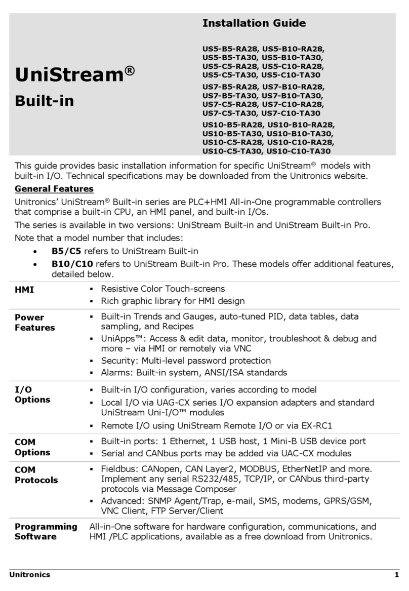
Unitronics US5-B10-RA28 User manual

Unitronics

Unitronics US5-B10-RA28 User manual

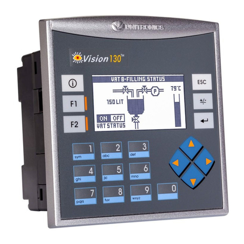
Unitronics Vision OPLC V130-J-TR20 User manual

Unitronics

Unitronics Vision OPLC V130-J-TR20 User manual

Unitronics Vision OPLC V130 User manual

Unitronics

Unitronics Vision OPLC V130 User manual

Unitronics V280 User manual

Unitronics

Unitronics V280 User manual

Unitronics MJ20-MEM1 User manual

Unitronics

Unitronics MJ20-MEM1 User manual

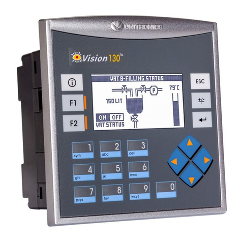
Unitronics Vision120 User manual

Unitronics

Unitronics Vision120 User manual

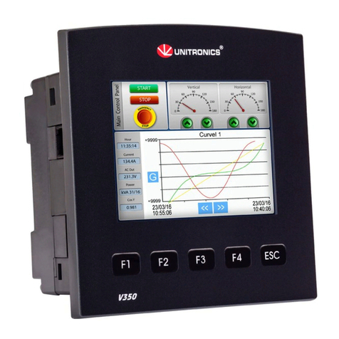
Unitronics Vision V350-35-T2 User manual

Unitronics

Unitronics Vision V350-35-T2 User manual

Unitronics Samba SM70-J-RA22 User manual

Unitronics

Unitronics Samba SM70-J-RA22 User manual

Unitronics Vision V130-J-TA24 User manual

Unitronics

Unitronics Vision V130-J-TA24 User manual

Unitronics UniStream USC-C3-R20 User manual

Unitronics

Unitronics UniStream USC-C3-R20 User manual

Unitronics V130-33-TR6 User manual

Unitronics

Unitronics V130-33-TR6 User manual

Unitronics UniStream USC-B5-R38 User manual

Unitronics

Unitronics UniStream USC-B5-R38 User manual

Unitronics V230 User manual

Unitronics

Unitronics V230 User manual

Unitronics Vision700 User manual

Unitronics

Unitronics Vision700 User manual

Unitronics Vision OPLC V350-35-TR20 User manual

Unitronics

Unitronics Vision OPLC V350-35-TR20 User manual

Unitronics UniStream USC-B3-R20 User manual

Unitronics

Unitronics UniStream USC-B3-R20 User manual

Unitronics Vision OPLC V350-35-TA24 User manual

Unitronics

Unitronics Vision OPLC V350-35-TA24 User manual

Unitronics Vision V130-J Series User manual
Unitronics

Unitronics Vision V130-J Series User manual

Unitronics Samba OPLC SM43-J-R20 User manual

Unitronics

Unitronics Samba OPLC SM43-J-R20 User manual

Unitronics MJ20-MEM1 User manual

Unitronics

Unitronics MJ20-MEM1 User manual

Unitronics UniStream USC-B10-RA28 User manual

Unitronics

Unitronics UniStream USC-B10-RA28 User manual

Unitronics Vision OPLC V1040-T20B User manual
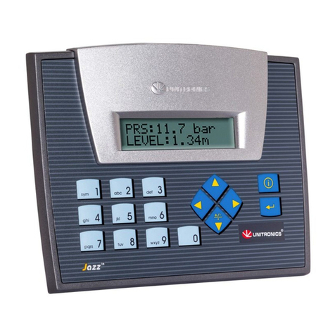
Unitronics

Unitronics Vision OPLC V1040-T20B User manual

Popular Controllers manuals by other brands

HALOGEN VALVE SYSTEMS Terminator Installation, operation and maintenance manual

HALOGEN VALVE SYSTEMS

HALOGEN VALVE SYSTEMS Terminator Installation, operation and maintenance manual

elco ELK 38 operating instructions

elco

elco ELK 38 operating instructions

Carrier PREMIERLINK 33CSPREMLK Installation and configuration guide

Carrier

Carrier PREMIERLINK 33CSPREMLK Installation and configuration guide

LEGRAND ALPTEC 5.2 instructions

LEGRAND

LEGRAND ALPTEC 5.2 instructions

Rice Lake 880 Performance Series Operation manual

Rice Lake

Rice Lake 880 Performance Series Operation manual

Cielo BREEZ PLUS user manual

Cielo

Cielo BREEZ PLUS user manual

TINY TNC-M14-CNC Operation manual

TINY

TINY TNC-M14-CNC Operation manual

Yudian AI-518 operation instruction

Yudian

Yudian AI-518 operation instruction

Roger PR311SE Function guide

Roger

Roger PR311SE Function guide

Linak TD4 quick guide

Linak

Linak TD4 quick guide

National Instruments NI PXI-6653 installation guide

National Instruments

National Instruments NI PXI-6653 installation guide

Altinex Wireless Touchscreen Controller CP451-008 user guide

Altinex

Altinex Wireless Touchscreen Controller CP451-008 user guide

bonitron M3460 Customer Reference Manual

bonitron

bonitron M3460 Customer Reference Manual

ESPEC P-300 CONFIGURATION AND TROUBLESHOOTING MANUAL

ESPEC

ESPEC P-300 CONFIGURATION AND TROUBLESHOOTING MANUAL

Christie E510 Technical reference

Christie

Christie E510 Technical reference

dIXEL XC450D operating instructions

dIXEL

dIXEL XC450D operating instructions

Levven GDT15 instruction sheet

Levven

Levven GDT15 instruction sheet

EME FINCOR 2230 MKII Series Equipment manual

EME

EME FINCOR 2230 MKII Series Equipment manual

manuals.online logo
manuals.online logoBrands
  • About & Mission
  • Contact us
  • Privacy Policy
  • Terms and Conditions

Copyright 2025 Manuals.Online. All Rights Reserved.