manuals.online logo
Brands
  1. Home
  2. •
  3. Brands
  4. •
  5. Universal Tool
  6. •
  7. Power Screwdriver
  8. •
  9. Universal Tool UT8963AT-5 User manual

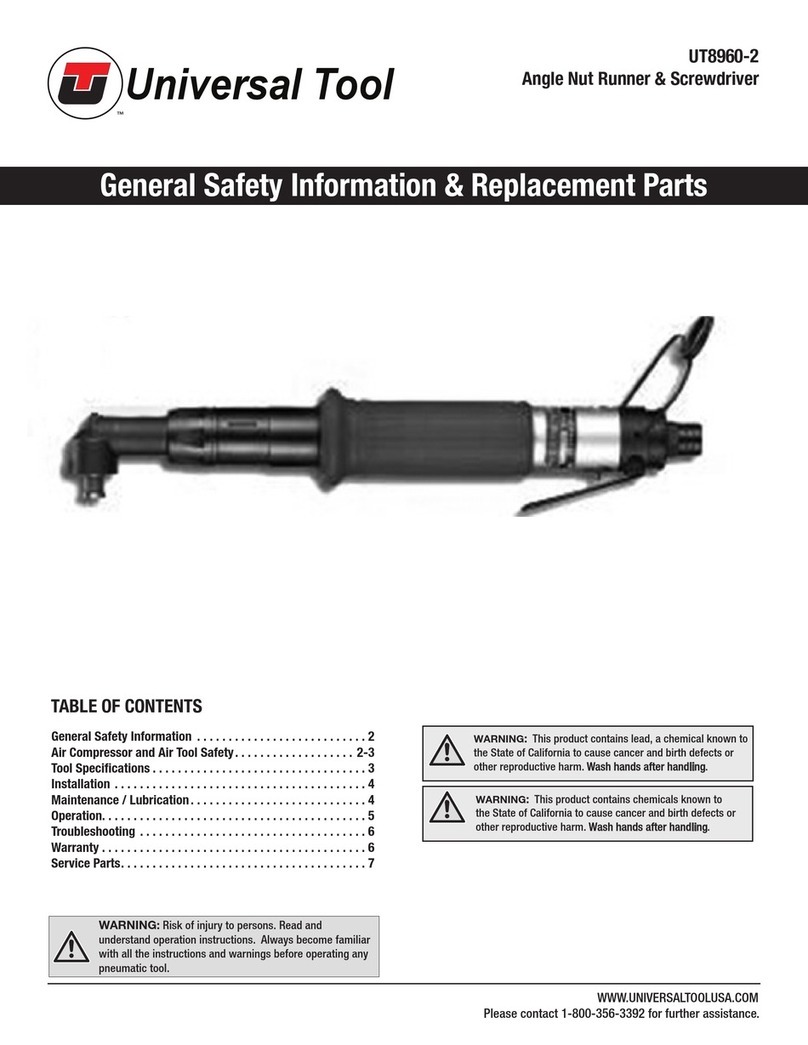
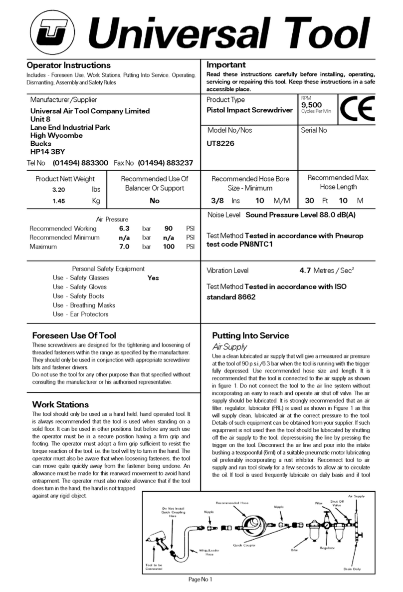
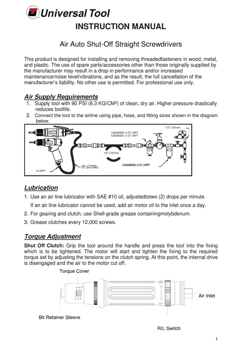
Universal Tool UT8963AT-5 User manual

UT8963AT-5
PLEASE READ AND FOLLOW ALL WARNINGS
Read Operating Instructions
Always become familiar with all the
instructions and warnings before
operating any power tool.
Always Wear Approved
Eye Protection
Impact resistant eye protection
should meet or exceed the
standards as set forth in the United
States ANSI Z87.1, Occupational
and Educational Eye and Face
Protection. Look for the marking
Z87.1 on your eye protection to
insure that it is an approved style.
For further information, ANSI Z87.1,
Occupational and Educational Eye
and Face Protection, is available
from the American National
Standards Institute, Inc., 11 West
42nd Street, New York, NY 10036.
Hearing Protection is
Recommended
Hearing protection should be used
when the noise level exposure
equals or exceeds an 8 hour time-
weighted average sound level of 85
dBA. Process noise, reflective
surfaces, other tools being
operated nearby, all add to the
noise level present in your work
area. If you are unable to determine
your noise level exposure, we
recommend the use of hearing
protection.
Avoid Prolonged Exposure to
Vibration
Tools can vibrate during use.
Prolonged exposure to vibration or
very repetitive hand and arm
movements, can cause injury.
Stop using any tool if discomfort,
tingling feeling or pain occurs. You
should consult your physician
before resuming use of the tool.
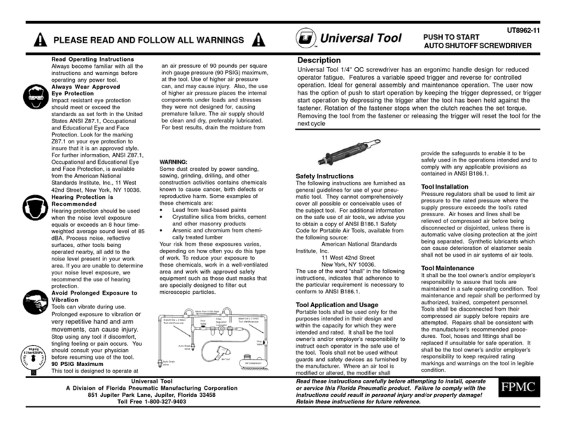
90 PSIG Maximum
This tool is designed to operate at
an air pressure of 90 pounds per square
inch gauge pressure (90 PSIG) maximum,
at the tool. Use of higher air pressure
can, and may cause injury. Also, the use
of higher air pressure places the internal
components under loads and stresses
they were not designed for, causing
premature failure. The air supply should
be clean and dry, preferably lubricated.
For best results, drain the moisture from
Universal Tool
A Division of Florida Pneumatic Manufacturing Corporation
851 Jupiter Park Lane, Jupiter, Florida 33458
Toll Free 1-800-327-9403
Read these instructions carefully before attempting to install, operate
or service this Florida Pneumatic product. Failure to comply with the
instructions could result in personal injury and/or property damage!
Retain these instructions for future reference.
Safety Instructions
The following instructions are furnished as
general guidelines for use of your pneu-
matic tool. They cannot comprehensively
cover all possible or conceivable uses of
the subject tool. For additional information
on the safe use of air tools, we advise you
to obtain a copy of ANSI B186.1 Safety
Code for Portable Air Tools, available from
the following source:
American National Standards
Institute, Inc.
11 West 42nd Street
New York, NY 10036.
The use of the word “shall” in the following
instructions, indicates that adherence to
the particular requirement is necessary to
conform to ANSI B186.1.
Tool Application and Usage
Portable tools shall be used only for the
purposes intended in their design and
within the capacity for which they were
intended and rated. It shall be the tool
owner’s and/or employer’s responsibility to
instruct each operator in the safe use of
the tool. Tools shall not be used without
guards and safety devices as furnished by
the manufacturer. Where an air tool is
modified or altered, the modifier shall
provide the safeguards to enable it to be
safely used in the operations intended and to
comply with any applicable provisions as
contained in ANSI B186.1.
Tool Installation
Pressure regulators shall be used to limit air
pressure to the rated pressure where the
supply pressure exceeds the tool’s rated
pressure. Air hoses and lines shall be
relieved of compressed air before being
disconnected or disjointed, unless there is
automatic valve closing protection at the joint
being separated. Synthetic lubricants which
can cause deterioration of elastomer seals
shall not be used in air systems of air tools.
Tool Maintenance
It shall be the tool owner’s and/or employer’s
responsibility to assure that tools are
maintained in a safe operating condition. Tool
maintenance and repair shall be performed by
authorized, trained, competent personnel.
Tools shall be disconnected from their
compressed air supply before repairs are
attempted. Repairs shall be consistent with
the manufacturer’s recommended proce-
dures. Tool, hoses and fittings shall be
replaced if unsuitable for safe operation. It
shall be the tool owner’s and/or employer’s
responsibility to keep required rating
markings and warnings on the tool in legible
condition.
FPMC
WARNING:
Some dust created by power sanding,
sawing, grinding, drilling, and other
construction activities contains chemicals
known to cause cancer, birth defects or
reproductive harm. Some examples of
these chemicals are:
•Lead from lead-based paints
•Crystalline silica from bricks, cement
and other masonry products
•Arsenic and chromium from chemi-
cally treated lumber
Your risk from these exposures varies,
depending on how often you do this type
of work. To reduce your exposure to
these chemicals, work in a well-ventilated
area and work with approved safety
equipment such as those dust masks that
are specially designed to filter out
microscopic particles.
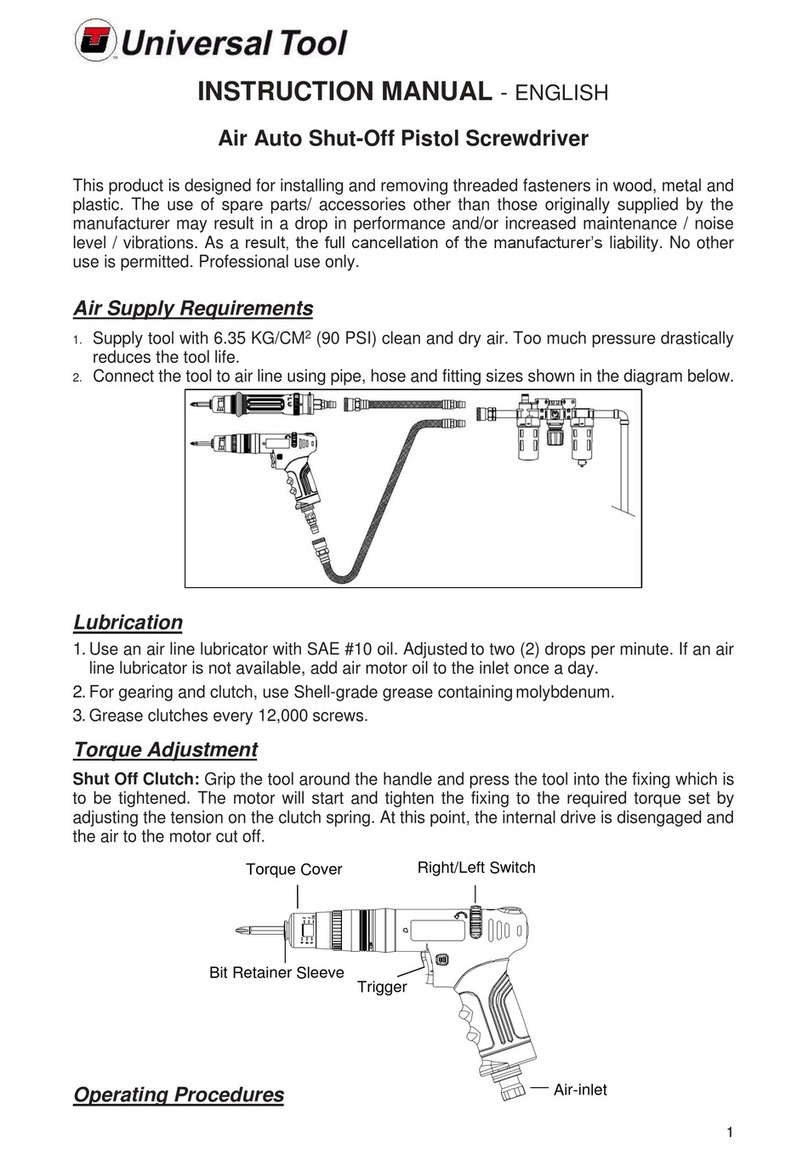
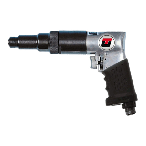
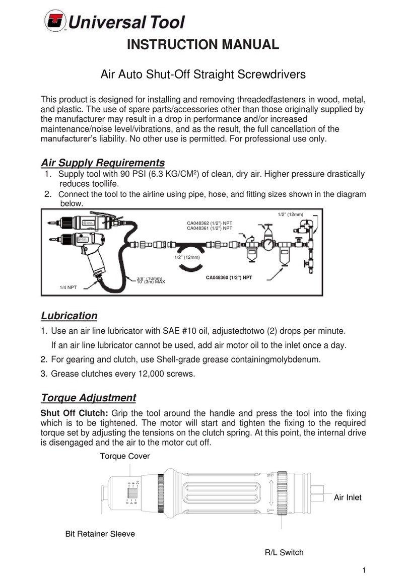
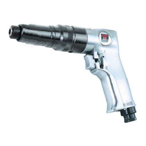
Description
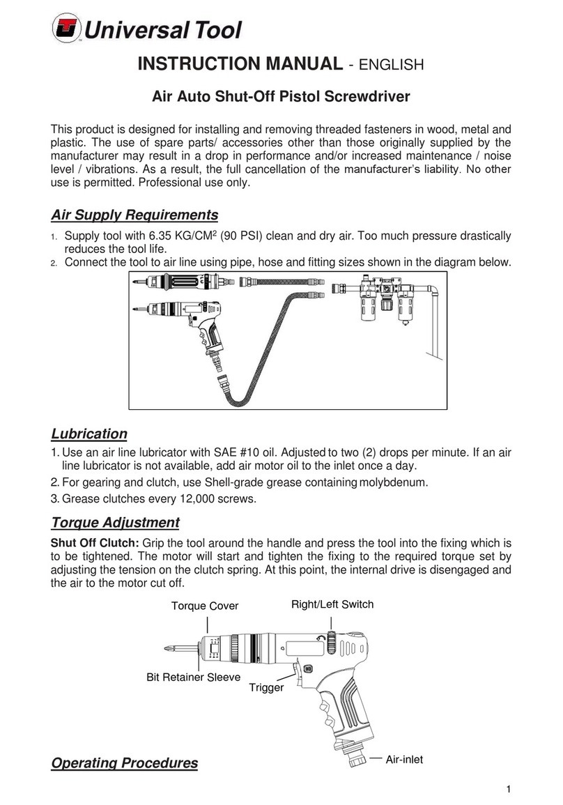
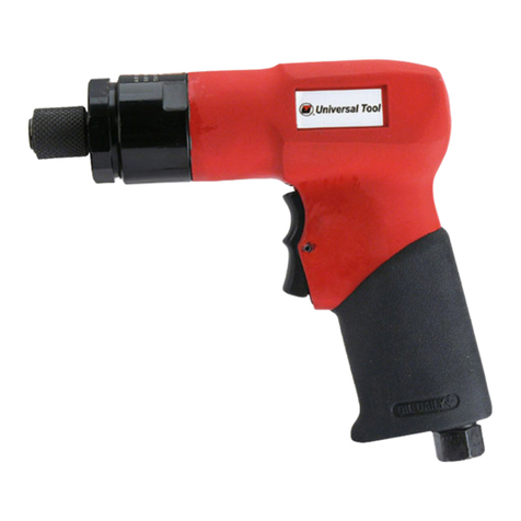
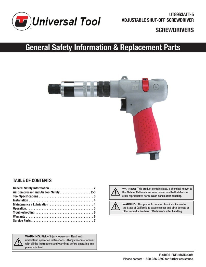
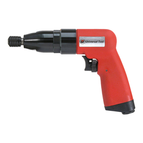
Universal Tool 1/4” QC screwdriver has an ergonimc handle design for reduced
operator fatigue. Features a variable speed trigger and reverse for controlled
operation. Ideal for general assembly and maintenance operation. The user now
has the option of push to start operation by keeping the trigger depressed, or trigger
start operation by depressing the trigger after the tool has been held against the
fastener. Rotation of the fastener stops when the clutch reaches the set torque.
Removing the tool from the fastener or releasing the trigger will reset the tool for the
next cycle
PUSH TO START
AUTO SHUTOFF SCREWDRIVER
Parts Breakdown for UT8963AT-5
Ref. Description Part # Ref. Description Part #
Replacement Parts for UT8963AT-5
UT8963AT-5 UT8963AT-5
PUSH TO START
AUTO SHUTOFF SCREWDRIVER
USE ONLY IMPACT SOCKETS & ACCESSORIES
Sockets and accessories used shall be of the impact socket type. Always check sockets,
retainers and drives regularly for wear or damage and replace whenever necessary
Limited Warranty
Universal Tool warrants its tools to be free from defects in material and workmanship for one year from the date of
purchase. This warranty does not apply to tools which have been abused, misused, modified or repaired by
someone other than Universal Tool or its authorized service centers. If a Universal Tool proves defective in
material of workmanship within one year after purchase, return it to any authorized service center or to Universal
Tool, freight prepaid. Please enclose your name, address and adequate proof of purchase date with a brief
description of the defect. Universal Tool will, at its option, repair or replace defective tools, free of charge. Repairs
or replacements are warranted as described above for the remainder of the warranty period. Universal Tool's sole
liability and your exclusive remedy under this warranty is limited to repair or replacement of the defective tool.
There are no other warranties expressed or implied and Universal Tool shall not be liable for incidental, consequential
or special damages, or any other damages, costs or expense of repair or replacement as described above.
Drive size .. ..........................................1/4" QC
Free speed (No load).........................550 RPM
Torque (green spring) ....................5-19 in/lbs.
Torque (black spring) .................. 10-38 in/lbs.
Torque (yellow spring) ................. 15-45 in/lbs.
Weight .. ..............................................1.98 lbs.
Overall length .... ......................................8.27"
Average air consumption ......................4 CFM
Recommended hose size . ...................3/8" I.D.
Air inlet . ..............................................1/4" NPT
Maximum operating pressure ........ .........90 psi
1Motor Housing 9AS00401
2Spring Pin 920448
3Air Inlet 9AS00503
4Trigger 9AS00404
5 Valve Stem 9AS00405
6 Valve Bushing 9AS00406
7O-Ring 9AS00447
8 Valve Spring 9AS00408
9O-Ring 9516114
10 Valve Stem 9AS00410
11 Valve Bushing 9AS00411
12 Shut-Off Valve Bushing 9AS00412
13 Ball Bearing (2) 9000022
14 End Plate 9000023
15 Rotor 9000024
16 Rotor Blades (4) 9000025
17 Spring Pin 9000026
18 Cylinder 9000027
19 Front End Plate 9000028
20 Motor Spacer 9000029
21 Push Needle 9000030
22 Internal Gear 9000031
23 Planet Gear (3) 9000032
24 Pin (6) 9000033
25 Bushing (6) 9000034
26 Reduction Spindle 9000035
27 Work Spindle 9000036
28 Center Gear 9000037
29 Planet Gear (3) 9000038
30 Ball Bearing 9000039
31 Inlet Noose 9000040
32 Reverse Valve 9000041
33 O-Ring (4) 9000042
34,75 O-Ring (2) 9000043
35 Clutch 9000044
36 Pin 9000045
37 Reset Pin 9000046
38 Pin 9000047
39 Trip Slide 9000048
40 Spring 9000049
41 Plug 9000050
42 Internal Ring 9000051
43 Steel Ball (4) 9000052
44 Spring 9000053
45 Cam Spindle 9000054
46 Cover 9000055
47 Bushing 9000056
48 C-Ring 9000057
49 Spring 9000058
50 Thrust Race (2) 9000059
51 Roller Thrust Bearing 9000060
52 Adjustment Lock Ring 9000061
53 Adjustment Nut 9000062
54 Spindle Bushing 9000063
55 Ball Retainer 9000064
56 Spring 9000065
57 Washer 9000066
58 Adjustment Cover 9000067
59 Clutch Housing 9000068
60 Retaining Ring 9000069
61 Spring Pin 9000070
62 Retainer Ring 9000071
63 Steel Ball (13) 9000072
64 Steel Ball 9000073
65 Rubber Grip 9AS00452
66 Shut Off Valve Seat (2) 9AS00509
67 Shut Off Valve 9AS00510
68 Shut Off Valve Spring 9AS00508
70 Valve Cap (2) 9AS00409
71 Reverse Valve Knob 9AS00421
72 Reverse Knob Spacer 9AS00433
73 Screw 9AS00432
74 Ring 9000083
77 Damping Material 9000086
78 Exhaust Diffuser 9AS00407
79 Air Inlet 9AS00403
80 Set Screw 910213
81 Hex Wrench 910020
82 Spring 9000097
83 Screwdriver 9AS000163
84 O-Ring 952235
85 O-Ring 9OR00200100
86 Washer 9AS00427
87 O-Ring 9OR01007105
PUSH TO START
AUTO SHUTOFF SCREWDRIVER
Clutch Adjustment
Clutches are adjusted through the slot
provided in the clutch housing. The slot
cover must be rotated to expose the
adjustment slot. Rotate (fig.58) the
clutch housing until the hole in the
adjustment nut is visible. Insert a No.1
Phillips screwdriver and rotate in a
clockwise direction to increase torque
setting or in a counter clockwise
direction to decrease the setting. After
each adjustment, the slot cover should
be rotated back to its locked posistion

Other Universal Tool Power Screwdriver manuals

Universal Tool UT8943 User manual

Universal Tool

Universal Tool UT8943 User manual

Universal Tool UT8963ATT-5 Manual

Universal Tool

Universal Tool UT8963ATT-5 Manual

Universal Tool UT8942 User manual

Universal Tool

Universal Tool UT8942 User manual

Universal Tool UT8965 User manual

Universal Tool

Universal Tool UT8965 User manual

Universal Tool UT8961-1 User manual

Universal Tool

Universal Tool UT8961-1 User manual

Universal Tool UT2964 User manual

Universal Tool

Universal Tool UT2964 User manual

Universal Tool UT8906 Specifications

Universal Tool

Universal Tool UT8906 Specifications

Universal Tool UT8963 User manual

Universal Tool

Universal Tool UT8963 User manual

Universal Tool UT8933 User manual

Universal Tool

Universal Tool UT8933 User manual

Universal Tool UT8963-17 User manual

Universal Tool

Universal Tool UT8963-17 User manual

Universal Tool UT8955 Specifications

Universal Tool

Universal Tool UT8955 Specifications

Universal Tool UT8962-11 User manual

Universal Tool

Universal Tool UT8962-11 User manual

Universal Tool UT8226 Specifications

Universal Tool

Universal Tool UT8226 Specifications

Universal Tool UT8963ATT-11 Manual

Universal Tool

Universal Tool UT8963ATT-11 Manual

Universal Tool UT8966 User manual

Universal Tool

Universal Tool UT8966 User manual

Universal Tool UT8955 User manual

Universal Tool

Universal Tool UT8955 User manual

Universal Tool UT8962-17 User manual

Universal Tool

Universal Tool UT8962-17 User manual

Universal Tool UT8818-S Manual

Universal Tool

Universal Tool UT8818-S Manual

Universal Tool UT8961 Specifications

Universal Tool

Universal Tool UT8961 Specifications

Universal Tool UT8934 User manual

Universal Tool

Universal Tool UT8934 User manual

Universal Tool UT8941 User manual

Universal Tool

Universal Tool UT8941 User manual

Universal Tool AINA PTT Specifications

Universal Tool

Universal Tool AINA PTT Specifications

Universal Tool UT2960A User manual

Universal Tool

Universal Tool UT2960A User manual

Universal Tool UT8963AT-17 User manual

Universal Tool

Universal Tool UT8963AT-17 User manual

Popular Power Screwdriver manuals by other brands

Makita 6802BV instruction manual

Makita

Makita 6802BV instruction manual

Berner BACIW BL COMPACT Original instructions

Berner

Berner BACIW BL COMPACT Original instructions

Black & Decker BDSG500 Linea PRO instruction manual

Black & Decker

Black & Decker BDSG500 Linea PRO instruction manual

Makita DFS251 instruction manual

Makita

Makita DFS251 instruction manual

DeWalt DW979 instruction manual

DeWalt

DeWalt DW979 instruction manual

Black & Decker 9036 instruction manual

Black & Decker

Black & Decker 9036 instruction manual

Bosch PSR 200 LI operating instructions

Bosch

Bosch PSR 200 LI operating instructions

Kilews SKD-BE203L Operation and maintenance manual

Kilews

Kilews SKD-BE203L Operation and maintenance manual

Makita 6827 instruction manual

Makita

Makita 6827 instruction manual

Makita BFT123F instruction manual

Makita

Makita BFT123F instruction manual

DeWalt DCD792 Original instructions

DeWalt

DeWalt DCD792 Original instructions

XTline XT102700 instructions

XTline

XTline XT102700 instructions

EINHELL TE-CI 12 Li Original operating instructions

EINHELL

EINHELL TE-CI 12 Li Original operating instructions

DeWalt XR LI-ION DCD931 user manual

DeWalt

DeWalt XR LI-ION DCD931 user manual

AEG BST18X2 Original instructions

AEG

AEG BST18X2 Original instructions

RODCRAFT RC4760 Operation manual

RODCRAFT

RODCRAFT RC4760 Operation manual

Festool C 12 Li Original operating manual and Spare parts list

Festool

Festool C 12 Li Original operating manual and Spare parts list

WolfPack KWSD08 instruction manual

WolfPack

WolfPack KWSD08 instruction manual

manuals.online logo
manuals.online logoBrands
  • About & Mission
  • Contact us
  • Privacy Policy
  • Terms and Conditions

Copyright 2025 Manuals.Online. All Rights Reserved.