UPLIFT 2-Leg Height Adjustable Standing Desk Quick setup guide

UPLIFT 2-Leg Height Adjustable Standing Desk
- For use with UPLIFT Eco and Eco Curve desktops -
DIRECTIONS FOR ASSEMBLY AND USE
Your UPLIFT Eco desktop is thinner than most desktops. Before attaching accessories,
check the screw length against the thickness of the desktop to ensure that the screw is
not too long and won’t break through to the top of your desktop.
If you have an UPLIFT Eco Curve desktop (where the edge tapers downat the center cut),
it is best to not attach anything underneath that portion of the desktop as the fasteners
used will assuredly be too long and will break through to the topside of your desktop.
Please Note
®
SAVE THESE INSTRUCTIONS:
Any user or installer of desk base must study this manual carefully. If this desk is sold,
please provide the manual to the buyer, installers, or support personnel operating the product.
TABLE OF CONTENTS PAGE
1 Safety and Warnings 2
2 Usage 2
3 Parts List 3
4 Assembly Instructions 4
5 Desk Placement 7
6 Programming 8
7 Troubleshooting 9
8 TechnicalSpecications 9
90.014.01.0158v.B FRM200/R02

2
2. USAGE
This height adjustable desk has an electric motor and is designed for use in dry work areas only. The desk
height is adjustable so that it can be positioned at the most ergonomically suitable height. These desks are
designed only for the purposes included in this manual. They should not be used in environments with high
humidity or dampness. Any other use is at user’s risk.
Do not move around, crawl, or lie under the desk frame. Do not sit or stand on the desk frame.
Children should never use the desk unless they are supervised by adults.
Liability: Under no circumstances does the manufacturer accept warranty claims or liability claims for dam-
ages caused from improper use or handling of the desk frame other than that which is described in this
operation manual.
1. SAFETY AND WARNINGS
When using an electrical furnishing, basic precautions should always be followed, including the following:
Read all instructions before using the desk.
FAILURE TO COMPLY WITH OR OBSERVE ALL INSTRUCTIONS AND WARNINGS REGARDING THE USE
OF THIS PRODUCT MAY RESULT IN SERIOUS PROPERTY DAMAGE OR BODILY INJURY.
DANGER - To reduce the risk of electric shock, Always unplug this furnishing from the electrical outlet be-
fore cleaning, or before putting on or taking off parts.
WARNING - Toreducetheriskofburns,re,electricshock,orinjurytopersons:
• Close supervision is necessary when this furnishing is used by, or near children, invalids, or disabled
persons. Keep children away from electric height-adjustable desks, control units, and keypads.
There is a risk of injury and electric shock.
• Use this table only for its intended use as described in these instructions. Do not use attachments
not recommended by the manufacturer.
• Keep the table close to the power socket/outlet to be easily accessible.
• Never operate this table if it has a damaged cord or plug, if it is not working properly, if it has been
dropped or damaged, or dropped into water.
• Keep the cords away from heated surfaces.
• Do not open any of the components: legs, control box, or keypad. There is a danger of electric
shock. Do not insert anything into any seam or opening.
• Keep all electrical components away from liquids.
•
Do not operate where aerosol (spray) products are being used or where oxygen is being administered.
• Do not use outdoors.
• Inappropriate use of this product may cause property or bodily injury.
• Check surroundings on all sides before using the desk. Body parts and property can be crushed if
trapped between an immobile obstacle and the desk’s range of motion.
• Ensure the length of power cords are accounted for when operating the desk. Monitors, comput-
ers, speakers, anything with a cord that is not long enough for the desk’s range of motion could be
pulled down or have its wires broken. Items pulled off the desk may cause other items to fall.
• Please provide this manual to any users, installers, or support personnel operating the product.
MAKE SURE NO OBSTACLES ARE IN THE DESK’S PATH AND ALL CORDS ARE
OF APPROPRIATE LENGTH FOR DESK TRAVEL. FAILURE TO COMPLY WITH
OR OBSERVE ALL ASSEMBLY, SAFETY, AND OPERATION INSTRUCTIONS AND
WARNINGS REGARDING THE USE OF THIS PRODUCT MAY RESULT IN SERIOUS
PROPERTY DAMAGE OR BODILY INJURY.
!

part Description Qty
Leg 2
Foot 2
Crossbar end 2
Crossbar rail 2
Side bracket 2
Adhesive pads 10
Control box 1
Keypad 1
Leveling studs (pre-installed in feet) 4
Cables (Power & two connector wires) 3
M6x14 Machine screw 24
M6x10 Machine screw 8
#10x1/2 Machine screw (not pictured) 8
#10x5/8 Wood screw (not pictured) 4
Cable clips (not pictured) 10
1
2
3
4
5
6
7
8
9
10
11
12
13
14
15
or
1
1
2
2
3
3
4
5
5
6
8
12
12
12
13
13
12
12
13
7
Foot
(qty 2)
Leg
(qty 2)
Crossbar rail
(qty 2)
Adhesive pads
(qty 10)
Control box
(qty 1)
Side bracket
(qty 2)
Leveling stud
pre-installed
(qty 4)
1 2 4
3 5
68
M6x14
Machine screw
(qty 24)
M6x10
Machine screw
(qty 8)
#10x1/2
Machine screw
(qty 8)
#10x5/8
Wood screw
(qty 12)
Cable clip
(qty 10)
10
1312
11
Please count all pieces before disposing of any carton or packing material. Use a padded or carpeted
area for assembly to avoid damage. For ease and safety, we recommend two people for assembly.
10
7
Crossbar end
(qty 2)
Keypad
one of two types
(qty 1)
9Cables
(qty 1 power cable and
2 connecting cables)
or
Philips Head Screwdriver and/or Power DrillTape Measure
Allen wrench (included)
Tools required
Components
x2
3. PARTS LIST
14 15

4
B. Position the Crossbar ends (part 3) on their sides. You will be inserting
the Legs (part 1) into the Crossbar ends (parts 3) from below. When positioned
correctly,themounttabswillbefacingup(g.1).
Now, place the Legs (part 1) into the Crossbar
ends(part3)intothebottom(g.2).
g.1
3
5
11
C. Using the supplied Allen wrench, insert four (4) M6x14
Machine screws (part 11) into the Crossbar ends, and rotate
each screw only a few turns. Do not tighten fully until step D.
If you drop a screw inside the Crossbar end, simply tilt
to retrieve the screw.
4. ASSEMBLY INSTRUCTIONS
A. FullyseparatetheCrossbarends(part3)youwillndtheCrossbarrails(parts4)inside.
3 3
4
4
D. Take the two Side brackets (part 5) and attach them to the Leg
assemblies, using four (4) M6x14 Machine screws (part 11) each. Use
the Allen wrench, and rotate each screw only a few turns. Do not
tighten fully until step D.
If you are having trouble getting all the screws started, it is because
other screws are too tight. You’ll need to back out some screws in
order to loosen the tolerance of the screw holes.
E. Once all of the parts are connected, you can now tighten the eight (8) Screws from Step B and the
eight (8) Screws from Step C (16 screws in total).
F.
Remove backing from the Adhesive pads (part 6) and position
along the assembly as shown. Be sure to not cover any of the holes.
1111
g.2
1 1
3
3 3

H. Your UPLIFT Eco desktop is pre-drilled with threaded
inserts. Place the desktop on the ground, with the pre-drilled
holes facing up, and carefully place the upside down desk base
on the underside of the desktop.
Adjust the width of the base so that the holes in the
bracket line up with the pre-drilled holes in the desktop.
I. Ensure that the base is lined up with the threaded
inserts in the underside of the desktop. Double check that
the screws you’re using are the correct ones; you need to
be using the #10-1/2’’ Machine screw (part 13).
Install as follows:
3 per Side bracket 6 total
1 per Crossbar end 2 total
J. Secure the Crossbar Rails at both ends using M6x10
Machine screws (part 12), qty 4 per side.
Ensure that the machine screw hits the metal center rail
by sliding the center rail as needed.
13
12
F. Slide Crossbar rails (part 4) back into Crossbar ends (part 3).
Make sure that the Crossbar rail (part 4) can slide all the way to
the end of the Crossbar end (part 3).
Ifitdoesn’tt,taketheCrossbarrailoutandipitover,withthe
slots facing inward. 4
3
3
G. Attach each Foot (part 2) with four (4)
M6x14 Machine screws (part 11) and tighten
bolts in a cross pattern.
22
1 1
11

6
9
L. Turn the assembled desk right-side up. With two people, grab the
desk by the frame and desktop equally, and turn the desk right-side up.
Note: Make sure no obstacles are in the desk’s path. Make sure cords
are a length that will accommodate the change in height.
If necessary, adjust the levelling studs underneith each foot
to level out your desk.
14
K. PlacetheKeypad(part8)sothatitsfrontrunsush
with the desktop edge (or recessed up to 1/8”). It can be
placed anywhere along the front edge of the desk, but we
recommend placing it near a side so it won’t interfere with
your chair or legs when seated. Use the pre-drilled hole
locations, or place where preferred.
Use the #10x5/8 Wood Screws (part 14) to attach the
Keypad (part 8) and the Control box (part 7) to the
desktop.
Note: Do not over-tighten the screws, or else you
may break the plastic. 8
7
14
K. Place the Control box (part 7) and ensure enough
clearance at the wire ports for cable connections.
Use the pre-drilled hole locations, or place where
preferred.
Use the #10x5/8 Wood Screws (part 14) to attach
the Keypad (part 8) and the Control box (part 7)
to the desktop.
Note: Do not over-tighten the screws, or else
you may break the plastic.
M. Connect the legs and keypad to the Control box with
theCables(part14).Youwillndthattheyallhangloose.
Once everything is connected, use the Cable clips (part 22)
to keep them snug up against the desktop, to prevent them
from getting caught on things under your desk.
15
10

5. DESK PLACEMENT
Following desk assembly, adjust the Leveling studs or casters (sold separately) on the feet so that the desk
is level and does not shift its position.
When moving the desk, if casters are not installed, use a two-person
lift and lift the desk so that it can be moved without dragging. Dragging the desk may cause the frame and
screws to pull loose from the desktop.
When moving the desk, DO NOT lift the desk by the desktop alone, or the frame, alone. Support both the
frame and the desktop equally. Favoring one over the other can stress the fasteners connecting the desk
frame to the desktop. Lower the desk completely and lift the desk by grasping the frame.
Choose a placement for the desk that’s a safe distance from window frames, radiators, furniture, etc., so
that people do not get stuck or trapped by the desk.
Check cord clearance, so that they don’t get jammed. Then connect the desk to the 120v outlet and the
desk is ready for use. Do not place any objects underneath the desk that are taller than 20’’.
N. Plug the Power Cord into a 110v outlet.
To program up to four presets:
Usetheup/downbuttonstondadesiredheight,thenpress“M”followedbyanumber1–4.
8
IMPORTANT! You must RESET the desk prior to use!
Press and hold the DOWN button on the Keypad until the desk reaches its
lowest height. Release the DOWN button. Press and hold the DOWN button
againuntiltheLEDdisplayreads“RST”orabout10secondsonnon-LEDkeypad
models. Release the DOWN button. Press and hold the DOWN button again until
the desk lowers a little bit more, slightly rises and stops. Release the DOWN button.
Your desk is now ready to use.
6. PROGRAMMING:
If you’ve purchased an UPLIFT Desk and the Advanced 1-touch digital keypad, press the DOWN button
ontheKeypaduntiltheframereachesitslowestposition.Measuretheheightoftheframefromtheoor
to the underside of the desktop and if the number on the LED display does NOT match your measure-
ment, follow these steps:
PressandholdtheDOWNbuttonagainuntiltheLEDdisplayreads“RST”
Pressandholdthe“M”button(about5seconds)untiltheLEDdisplaystheashingstartingheight.
(Ifthedisplayreturnsto“RST”beforethenextstepistaken,repeatthisstep.)
To change the value of the starting height:
By 0.1s:
Increase: press the UP button
Decrease: press the DOWN button
Oncethenewvalueisdisplayed,waitabout5secondsandthedisplaywillreturnto“RST”.Finish
the reset process by pressing and holding the DOWN button again until the desk lowers a little bit
more, slightly rises and stops. Release the DOWN button. The new starting height value is saved
and your desk is now ready to use.
Note: the LED display has a 0.1 tolerance.
+
-
By 1.0s:
Increase:pressthe“l”button
Decrease:pressthe“2”button
By 10.0s:
Increase:pressthe“3”button
Decrease:pressthe“4”button
SETTING THE LED RETRACTED HEIGHT

8
This frame is designed to go to its minimum and maximum heights, allowing for the widest pos-
sible range. If you prefer to change the settings to a more narrow range, follow these steps:
Make sure the power is ON and a number reads in the LED display (if no number appears, please
follow the Reset procedure described in the TROUBLESHOOTING section below).
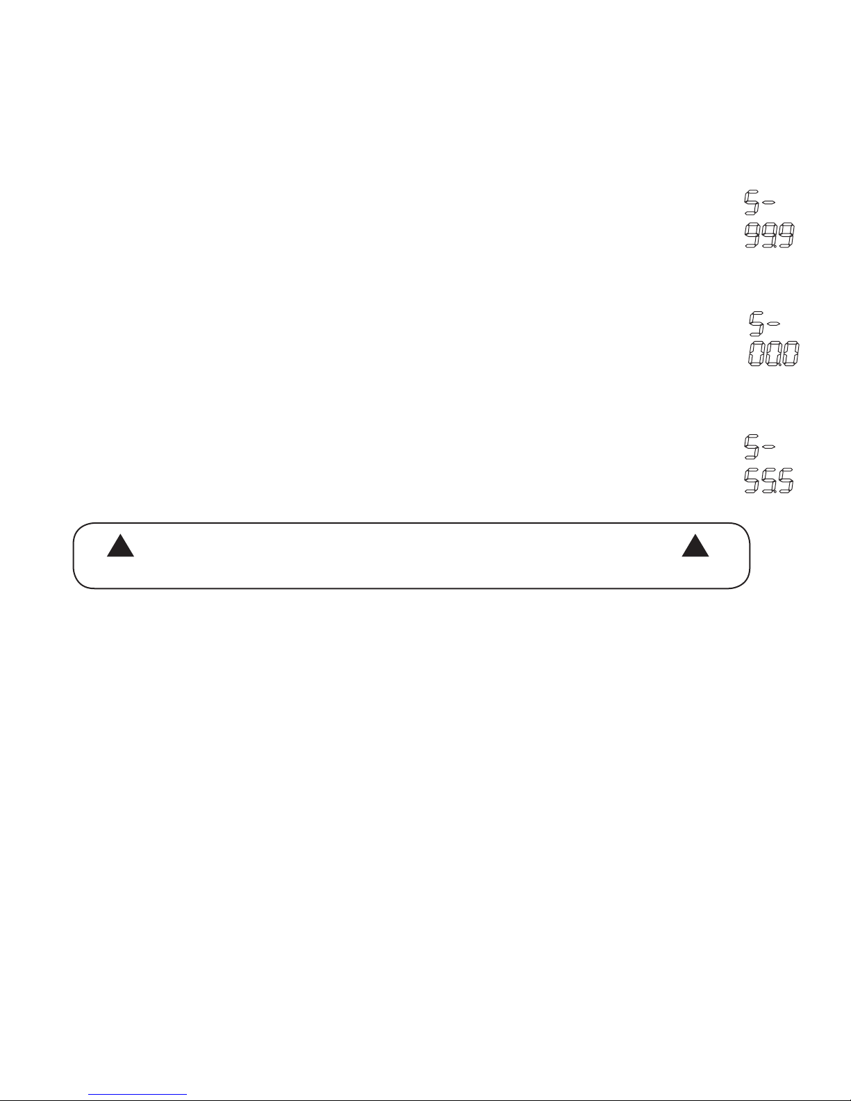
To Set the Upper-Limit Position:
Use the UP/DOWN buttons to move the frame to the desired maximum height position.
MakesuretheUPbuttonwasthelastbuttonyoupushed.Pressandholdthe“M”button
untiltheLEDdisplayashes“S-”onceandletgoofthebuttonThenpressandrelease
thebutton2moretimesinquicksuccession.TheLEDdisplaywillchangeto“999”onthe
third push, and then automatically return to the selected height. The new upper limit is
now set.
To Set the Lower-Limit Position:
Use the UP/DOWN buttons to move the frame to the desired minimum height position.
MakesuretheDOWNbuttonwasthelastbuttonyoupushed.Pressandholdthe“M”but-
tonuntiltheLEDdisplayashes“S-”onceandletgoofthebutton.Thenpressandre-
leasethebutton2moretimesinquicksuccession.TheLEDdisplaywillchangeto“000”
on the third push, and then automatically return to the selected height. The new lower
limit is now set.
To Remove the Upper/Lower Limit Positions:
Use the UP or DOWN button to move the desk to any new position. Press and hold the
“M”buttonuntiltheLEDdisplayashes“S-”onceandletofthebutton.Thenpressand
releasethebuttoninsuccessionuntilthedisplaychangesto“555”(ignoreanyinterim
readings). After a few seconds, the display will automatically change back to the num-
bered height position.The upper and lower limits are now removed.
A RESET procedure requires the desk frame to fully retract (beyond
any lower limit set). Please ensure that you have the proper clear-
ance below the desk frame.
After the upper and lower limits are set, the previous memory positions (l, 2, 3, 4) may be outside
the new range of movement. If so, simply reset the memory positions.
If you attempt to revise a previously set upper or lower limit and it is outside of the existing range,
youwillneedtoremovethepreviouslysetupper/lowerlimitsrst.
! !
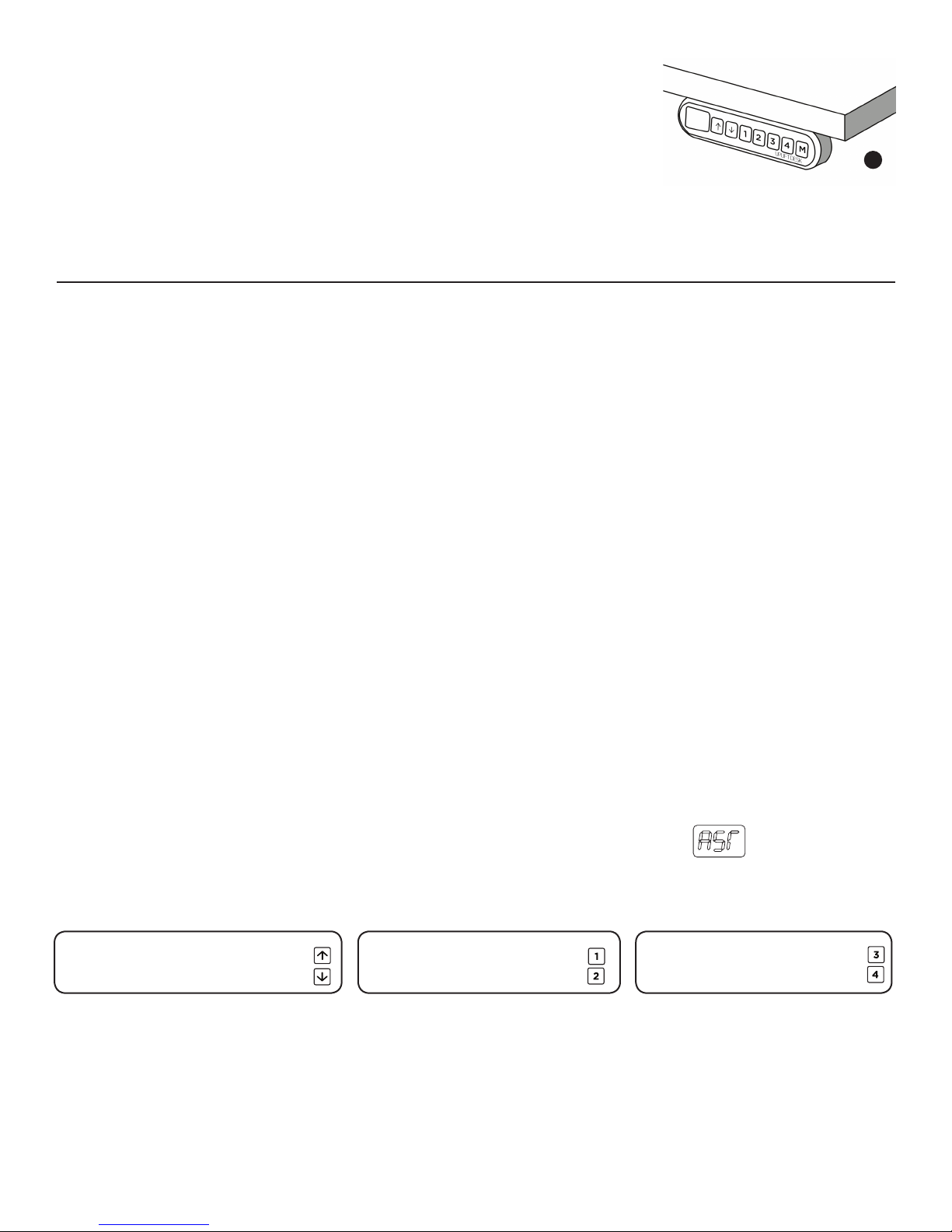
SETTING THE UPPER & LOWER LIMITS (Advanced 1-touch digital keypad only)
6. PROGRAMMING (continued):
7. TROUBLESHOOTING
--Reset Instructions--
If experiencing error messages showing on the Keypad or no response when trying to raise or lower:
• Unplug the power cord and hold the DOWN button for 30 seconds.
• Plug the power cord back in.
• Press and hold the DOWN button on the Keypad until the desk reaches its lowest height. Release the
DOWNbutton.PressandholdtheDOWNbuttonagainuntiltheLEDdisplayreads“RST”orabout10
seconds on non-LED keypad models. Release the DOWN button. Press and hold the DOWN button
again until the desk lowers a little bit more, slightly rises and stops. Release the DOWN button. Your
desk is now ready to use.
• The Keypad will then display the current height, and you should be able to operate it now.
• You may need to do this if the desktop is ever unplugged or loses power.
IftheKeypaddisplayserrormessages“Er1”through“Er13”,conrmthatallwiredconnectionsaresecure
(legs to cables, cables to control box). Then perform the reset procedure above. If the error message per-
sists after the reset procedure or if the height between the legs exceeds 1.5’’ stop the reset procedure and
IftheKeypaddisplays“Hot”,letthebasecooldownfor20minutes.
If the desk seems to be uneven, try the reset instructions above. If that does not work you may need to
adjust the levelers at the bottom of the foot.

8. TECHNICAL SPECIFICATIONS
Height Range 24.5” - 50.25” (without desktop)
Base Width 42.125” min - 74.75” max
Travel Speed 1.5” per second (varies, slowest w/ maximum load)
Weight Capacity 353 lbs.
Duty Cycle 10%, Max. 2 mins on, 18 mins off
4 Memory presets
Soft Start/Stop
Adjustable leveling studs
Copyright Notice:
This guide is a component of the UPLIFT Desk
™
. This guide is a part of the scope of delivery, even if the item is resold. This guide is also available on
the UPLIFT Desk website: upliftdesk.com. Excerpts or copies may not be forwarded to third parties or used in any other published form without the prior written consent
of UPLIFT Desk.
These instructions are subject to United States copyright law.
©
Keep children away from electric height-adjustable desks, control units,
and keypads. There is a risk of injury and electric shock.
If casters are not installed, use a two-person lift and lift the desk so that it can be moved without
dragging. Dragging the desk may cause the frame and screws to pull loose from the desktop.
This product is designed with a duty cycle of 10%.
(2 min. on, 18 min. off)
In the event of a power outage or if the power cord is unplugged,
a manual reset may be necessary. (see Reset Instructions above)
Do not open any of the components: lifting columns, control box,
or keypad. There is a danger of electric shock.
Keep all electrical components away from liquids.
i
i
!
!
!
!
Table of contents
Other UPLIFT Indoor Furnishing manuals
Popular Indoor Furnishing manuals by other brands

Knight
Knight Cubit Credenza Assembly instructions

Bunkers
Bunkers LOLINE LONGWALL Series Assembly instructions

Hafele
Hafele Moovit drawer Mounting instructions

Jysk
Jysk LUDVIKA 701-16-1002 quick start guide

Presidential Billiards
Presidential Billiards CARMEL Assembly instructions

physa
physa FR-6 user manual