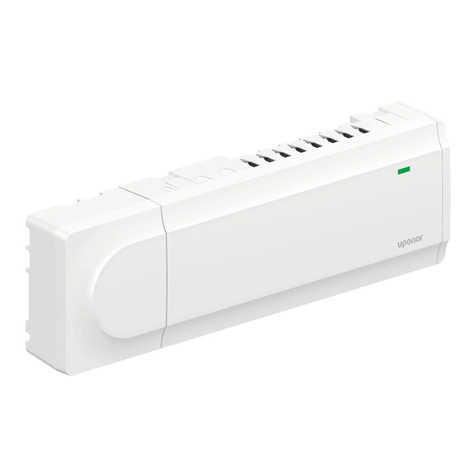
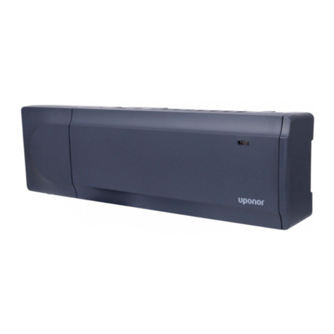
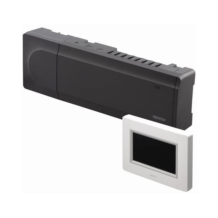
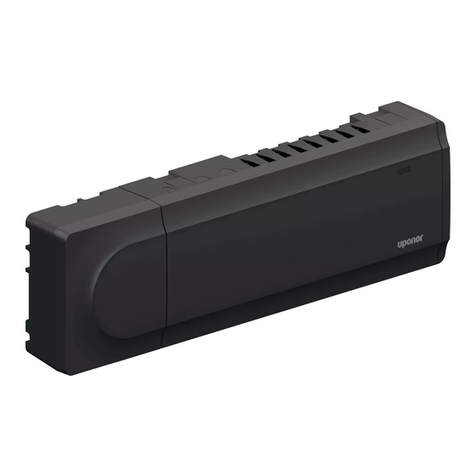
Uponor X-60 User manual

Uponor Base controller H pump X-60 6x 230V
EN Operation manual
CD0000608

Table of contents
1 Safety instructions and disclaimer..................................... 3
1.1 Safety instructions................................................................... 3
1.2 Correct disposal of this product (Waste Electrical and
Electronic Equipment)............................................................. 3
1.3 Copyright and disclaimer........................................................ 3
2 System description............................................................... 5
2.1 Autobalancing for more comfort and efficiency....................... 5
2.2 System compatibility............................................................... 5
2.3 Controller features.................................................................. 5
2.4 Components of the controller.................................................. 6
3 Operation............................................................................... 9
3.1 Controller cover opening......................................................... 9
3.2 Controller operation principle.................................................. 9
3.3 Start the controller................................................................. 10
3.4 Operating modes.................................................................. 10
4 Run mode............................................................................. 11
4.1 Example of a controller in run mode..................................... 11
4.2 Features................................................................................ 11
4.3 Autobalancing....................................................................... 11
4.4 ON/OFF outputs management.............................................. 11
4.5 Pump management............................................................... 11
4.6 Valve exercise....................................................................... 11
4.7 Day/night switch.................................................................... 12
4.8 Factory reset......................................................................... 12
5 Assignment mode............................................................... 13
5.1 Change from run mode to assignment mode........................ 13
5.2 Set up the assignment mode................................................ 13
5.3 Enter the assignment mode with assigned thermostats/
actuators............................................................................... 13
5.4 Assign the thermostats and actuators................................... 13
5.5 Check assigned channels..................................................... 15
5.6 Remove assigned channels.................................................. 16
5.7 Change back to run mode..................................................... 16
6 Maintenance........................................................................ 17
6.1 Manual preventive maintenance........................................... 17
6.2 Automatic preventive maintenance....................................... 17
6.3 Corrective maintenance........................................................ 17
7 Troubleshooting.................................................................. 18
7.1 General................................................................................. 18
7.2 Troubleshooting after installation.......................................... 18
8 Technical data..................................................................... 20
8.1 Technical specifications........................................................ 20
8.2 Dimensions........................................................................... 21
8.3 Wiring diagram...................................................................... 21
2 | Uponor Base controller H pump X-60 6x 230V | Operation manual

1 Safety instructions and disclaimer
1.1 Safety instructions
Safety messages used in this
document
Warning!
Risk of injury and damage. Ignoring warnings can cause
personal injury and/or damage to products and other
property.
Caution!
Risk of malfunctions. Ignoring cautions can cause the
product to not operate as intended.
Note
Important information to the section in the manual.
Uponor uses safety messages in the document to indicate special
precautions required for the installation and operation of any Uponor
product.
Safety measures
Note
For safe and proper use, obey the instructions given in
this document. Keep them for future reference.
The installer and operator agree to comply with following measures
regarding Uponor products:
• Read and obey the instructions and processes in the document.
• The installation must be performed by a qualified installer in
accordance with local regulations.
• Uponor is not liable for modifications not specified in this
document.
• Switch off all connected power supplies before starting any
wiring work.
• Do not expose the Uponor components to flammable vapours or
gases.
• Do not use water to clean electrical Uponor products/
components.
Uponor is not liable for damage caused by ignoring the instructions in
this document or the applicable building code.
Power
Warning!
Uponor system power supply: 230 V AC, 50 Hz.
In case of emergency, immediately disconnect the power.
Technical constraints
Caution!
To avoid interference, keep data cables away from
components bearing power of more than 50 V.
1.2 Correct disposal of this
product (Waste Electrical and
Electronic Equipment)
Note
Applicable in the European Union and other European
countries with waste separation systems.
This icon on the product, or in the related documents
indicates that it should not be disposed with household waste.
Please, recycle responsibly to support the sustainable use of
resources and prevent possible harm to human health and/or the
environment.
Household users should contact the retailer where they purchased
this product, or their local government office, for details on where and
how they can take it for recycling.
Business users should contact their supplier and check the terms and
conditions of the purchase contract. Do not dispose this product with
other commercial waste.
1.3 Copyright and disclaimer
This is a generic, European-wide document version. The document
may show products that are not available in your location for
technical, legal, commercial, or other reasons.
For any questions or queries, please visit the local Uponor website or
speak to your Uponor representative.
“Uponor” is a registered trademark of Uponor Corporation.
Uponor has prepared this document solely for information purposes,
images are only representations of the products. The content (text
and images) of the document is protected by worldwide copyright
laws and treaty provisions. You agree to comply with these when
using the document. Modification or use of any of the content for any
other purpose is a violation of Uponor’s copyright, trademark, and
other proprietary rights.
This disclaimer applies to, but is not limited to, the accuracy,
reliability, or correctness of the document.
The presumption for the document is that the product related safety
instructions are fully obeyed. The following requirements apply to the
Uponor product (including any components) as covered by the
document.
• The system (combination of products) is selected and designed
by a competent planner. It is installed and put into operation by a
licensed and/or competent installer in compliance with the
instructions provided by Uponor. Locally applicable building and
plumbing codes/regulations have been obeyed.
• Temperatures, pressure and/or voltage limits according to
product and design information have not been exceeded.
• The product remains in its originally installed location and is not
repaired, replaced, or interfered with, without prior written
consent of Uponor.
• The product is connected to potable water supplies or
compatible plumbing, heating and/or cooling systems approved
or specified by Uponor.
Uponor Base controller H pump X-60 6x 230V | Operation manual | 3
• The product is not connected to or used with third-party
products, parts, or components except for those approved or
specified by Uponor.
• The product does not show evidence of tampering, mishandling,
insufficient maintenance, improper storage, neglect, or
accidental damage before installation and being put into
operation.
While Uponor has made all effort to ensure that the document is
accurate, the company does not guarantee or warrant the accuracy
of the information. Uponor reserves the right to change the product
portfolio and the related documentation without prior notification, in
line with its policy of continuous improvement and development.
Always make sure that the system or product complies with
current local standards and regulations. Uponor cannot
guarantee the full compliance of the product portfolio and
related documents with all local regulations, standards, or
working methods.
Uponor disclaims all warranties related to the content of this
document, expressed or implied, to the fullest extent
permissible unless otherwise agreed or statutory.
Uponor is under no circumstances liable for any indirect,
special, incidental, or consequential damage/loss that results
from the use or inability to use the product portfolio and related
documents.
This disclaimer and any provisions in the document do not limit
any statutory rights of consumers.
4 | Uponor Base controller H pump X-60 6x 230V | Operation manual

2 System description
CD0000605
Uponor Base controller H pump X-60 6x 230V (controller X-60) is one
of the core components in radiant heating systems. It controls the
heating source, pump, and actuators to adjust the indoor temperature
in each room based on transmitted demand signals from the
thermostats.
2.1 Autobalancing for more
comfort and efficiency
When a conventional radiant heating system is installed, it is
necessary to balance it manually to make sure that each room
receives the required output. If the system is kept unbalanced with a
constant flow rate, some rooms can be overpowered while others are
underpowered. A system that is not properly balanced requires more
energy to adequately heat all rooms.
The autobalancing technology of the controller X-60 offers a more
energy efficient system than a manually balanced system. It
constantly calculates and adjusts the accurate energy quantity to
keep an optimal comfort in each room. Another advantage is that it is
not necessary to balance the system during the initial start.
In renovation projects, the autobalancing feature can easily be
adapted to an available installation without any new calculation. In a
conventional radiant heating system, also small changes in a building
interior can have an effect on the temperature balance. One reason
can be that the required quantity of water at a given supply
temperature is necessary to change due to a replacement of floor
covering. The autobalancing feature in the controller X-60 can
automatically adapt to these changes, to keep the comfort.
2.2 System compatibility
Note
For more detailed information, product range and
documentation please visit the Uponor website:
www.uponor.com.
The autobalancing controller X-60 is compatible with Uponor Base
thermostats 230 V. This controller is also compatible with other 230 V
thermostats available on the market.
Third-party thermostats
Warning!
The installer must make sure that the thermostat is
compatible with the controller before the installation is
done.
Following minimum requirements must be obeyed if third-party
thermostats should be connected to the controller.
• 2 wires for power supply 230 V
• 1 output 230 V for the demand
Following feature is an optional requirement.
• Day/night input
2.3 Controller features
Main hardware characteristics of this controller:
• 230 V AC input.
– 1 power LED (green).
• Digital inputs: day/night switch.
• Pump relay.
• Can operate up to 6 thermostats:
– 4 connectors per thermostat (L – N – Demand and output
for day/night switch).
– 6 red thermostat channel LEDs, which are used during the
connection process.
• Can operate up to 12 actuators, with 2 actuators at a time that
follow a common thermostat:
– 6 double noiseless actuator outputs (triacs).
– 6 bi-colour actuator output LEDs which are used during the
connection process and to indicate the actuator status.
• 3 push buttons: Thermostat (>), "OK", Actuator (>).
• 1 switch to enable/disable the autobalance function.
Uponor Base controller H pump X-60 6x 230V | Operation manual | 5

Software features
Main characteristics of the controller software:
• Output management (set by default).
– Autobalancing (set by default).
– ON/OFF outputs management.
• Pump management.
• Valve exercise.
• Day/night switch.
• Assignment of input – output (thermostats – actuators).
• Factory reset.
2.4 Components of the controller
L
N
CD0000591
RELAY
(PUMP)
230V
5A max
L
B EC DG
F
HG MP
K
J
L
A
O Q
NR
I
Item Description
A Fuse (T5 6.3 A)
B Power module 230 V AC, 50 Hz
C Power LED
D LEDs for thermostat channels 1-6 (TH1-TH6)
E Thermostat connection terminals 1-6
F Push buttons for channel registration
G Holes for wall installation
H Power input 230 V AC
I Strain relief for the 230 V power cable
J Optional output for pump management (ON/OFF switch)
Item Description
K Day/night input
L Clips to lock and unlock the controller from the DIN rail
M Autobalancing switch
N Cable entry
O Cable guides
P LEDs for actuator channels 1-6
Q Actuator output, 12 terminals (1a-1b, 2a-2b ... 6a-6b)
R Safety partition between the push buttons and the connection
terminals
6 | Uponor Base controller H pump X-60 6x 230V | Operation manual

Overview of the LED colours
CD0000594
A
C
B
Item Description Condition
Colour Assignment mode Run mode
A Power LED Solid green Run mode ON
Flashing green Assignment mode ON
B Thermostat channel LED Solid red Thermostat selected/assigned
Flashing red Thermostat pointed
C Actuator channel LED Solid red Heating demand
Solid green Actuator assigned
Flashing red Actuator pointed
Flashing green Actuator selected
The different controller LEDs and their colours are clarified in
separate sections in this document.
Push buttons for channel registration
CD0000595
A
C
B
Item Description
A Thermostat button (>)
B "OK" - confirmation button
C Actuator button (>)
There are 3 push buttons on the right-hand side of the controller.
They are used for assignment, and for factory reset.
Label with a QR code on the cover
PDF
w
w
w
https://www.uponor.com/doc/1138349
SI0000633
There is a label with a QR code in the lower left-hand corner of the
transparent cover. It is a link to the product documentation on the
website.
Do not remove this label. Keep it for future reference to easily find the
related documentation.
Uponor Base controller H pump X-60 6x 230V | Operation manual | 7

Safety partition
Warning!
Risk of electric shock!
Do not touch the connected cables when the controller is
powered. The unit operates with a 230 V AC voltage.
SI0000631
There is a safety partition between the push buttons for channel
assignment, and the thermostat - and actuator connection terminals.
This wall prevents that the fingers accidently touch the connected
cables during the assignment.
The cables are under power supply during the assignment and can
cause an electric shock if a cable is not correctly connected.
8 | Uponor Base controller H pump X-60 6x 230V | Operation manual

3 Operation
3.1 Controller cover opening
Warning!
Uponor system power supply: 230 V AC, 50 Hz.
In case of emergency, immediately disconnect the power.
Warning!
Preferably use a 5 mm screwdriver to remove the
transparent cover.
A too large screwdriver can damage the controller parts.
Any installation and assignment that should be done requires that the
transparent cover is removed from the controller body. There are two
(2) clips on each side of the cover that locks the cover to the body.
Follow these steps to remove the transparent cover.
SI0000623
12
1
2
1
2
4
35
5 mm > 5 mm
1. Position a flat screwdriver in the clip hole in the first corner.
2. Gently push the screwdriver to the opposite side of the controller
body to release the first clip.
3. Repeat steps 1 and 2 on the second clip.
4. If necessary, repeat the steps 1 and 2 on the other side of the
controller.
5. Use your hands to gently remove the cover from the controller
body.
3.2 Controller operation principle
Warning!
The autobalancing controller 230 V is compatible only
with 230 V thermostats.
The autobalancing controller operates the radiant heating system
based on customer needs. The indoor temperatures are measured
and adjusted with thermostats located in each room.
If the temperature in a room is lower than the setpoint temperature,
the thermostat sends a demand signal to the controller to change the
temperature. The controller opens the related actuator based on
current operating mode and settings. Once the set temperature is
reached in the room, the signal from the thermostat stops and the
controller closes the actuator.
Uponor Base controller H pump X-60 6x 230V | Operation manual | 9

3.3 Start the controller
The first time the controller is started, it is by default in assignment
mode since no thermostat or actuator has been assigned yet. If no
button is pushed during 10 minutes, the controller goes to run mode.
When at least one thermostat and actuator have been assigned, the
controller starts in run mode by default.
3.4 Operating modes
The controller X-60 can operate in two different modes. Each mode is
described in a separate chapter.
Chapter Operating mode
4 Run mode
5 Assignment mode
The controller is in run mode during normal operation.
10 | Uponor Base controller H pump X-60 6x 230V | Operation manual

4 Run mode
4.1 Example of a controller in run
mode
CD0000596
Run mode - thermostat 1 (channel 1 and 2) and thermostat 2
(channel 3) with heating demand.
The controller is in run mode during normal operation.
The power LED is solid green when the system is powered.
The controller opens and closes the actuators based on demand
signals from the thermostats and the setup of the system. An affected
actuator LED shows a solid red light when there is a heating demand.
4.2 Features
Section Feature
4.3 Autobalancing
4.4 ON/OFF outputs management
4.5 Pump management
4.6 Valve exercise
4.7 Day/night switch
4.8 Factory reset
The available features in run mode are given in separate sections.
4.3 Autobalancing
Note
The Uponor Base controller can operate the actuator
outputs either by ON/OFF signals directly given by the
thermostats, or by the autobalancing.
Autobalancing is ON by default.
16
17
18
19
20
21
22
°C
DI0000016
C A B
Item Description
A Manual balancing
B Autobalancing
C Setpoint value
Autobalancing is a feature where the system calculates the actual
energy demand in the individual rooms, and adjusts the output of
each loop based on its length. This means that a short loop can
receive 20 % of the output while a long loop can receive about 60 %.
The autobalancing continues throughout the seasons, changed
lifestyle and usage patterns in the household, and prevents the need
of manual balancing. The ON/OFF signals are calculated by an
algoritm. This gives smoother floor temperatures and faster system
reaction times with lower energy consumption than a standard
ON/OFF system.
A manual hydraulic balancing only takes the initial conditions and
calculations into account. The autobalancing feature adjusts the
changes in the system or room automatically without any need for the
installer to make complex re-calculation or adjustment.
When autobalancing is ON, also during periods of demand, the
actuators are opening and closing to make sure that only the required
energy is used by the room. There is a time limit bypass function in
the controller to avoid that the pump and/or boiler is damaged due to
short ON/OFF periods. If the last ON period is too short, the
remaining open actuator stays open until there is a demand in
another room or during maximum 30 minutes.
4.4 ON/OFF outputs management
Bi-metal or electronic ON/OFF thermostats that are connected to the
radiant heating system send demand signals to the controller.
When there is no heating demand from the thermostat to the
controller, the LEDs of the actuators assigned to the thermostat are
turned OFF. The actuators are closed.
When the controller receives a heating demand signal from a
thermostat, the affected actuators open. The actuator channel LEDs
are solid red to indicate the demand status.
4.5 Pump management
The pump is powered externally. The relay switch turns ON the pump
when an actuator is open due to a demand.
If any actuator is open due to a valve exercise, the pump is not
activated.
There is a delay of 2 minutes during the pump startup (when it goes
from stop mode to run mode). During this time, the actuator opens
completely to make sure that there is a water flow.
4.6 Valve exercise
The controller is equipped with an automatic valve exercise function.
This function prevents the valve and actuators from stucks due to
inactivity.The exercise operates if a valve is closed for 3,5 days.
During this exercise, the valve is open for 2 minutes.
This valve exercise does not create any demand signal. Hence the
pump is not activated during the exercise. The actuator LED will not
turn ON as there is no demand.
Uponor Base controller H pump X-60 6x 230V | Operation manual | 11

4.7 Day/night switch
When thermostats with day/night functions are connected to the
controller X-60, the function can be used in the underfloor heating
system. The controller sends a signal to those thermostats to switch
between day and night mode.
4.8 Factory reset
Note
All thermostat and actuator assignments are deleted
when the controller is reset to factory settings.
Follow these steps to factory reset the controller when it is in run
mode.
CD0000592
10 sec
1
1. Press and hold all 3 buttons for up to 10 seconds.
CD0000593
2
2. All the thermostat and actuator assignments are deleted.
12 | Uponor Base controller H pump X-60 6x 230V | Operation manual

5 Assignment mode
IC0000155
Warning!
Risk of electric shock!
Do not touch the connected cables when the controller is
powered. The unit operates with a 230 V AC voltage.
Caution!
Always complete the connection of all cables before the
assignment procedure starts.
Note
The illustrations that are used in this document to
visualise the step instructions give the controllers without
any cables connected. This is done only to increase the
readability of the illustrations.
CD0000588
When the thermostats and actuators have been correctly connected
to the controller, they must be assigned to the controller. The
assignment is done in the assignment mode in the controller.
The power LED flashes green when the operating mode in the
controller has been changed to assignment mode and the system is
ON.
The LEDs in already assigned thermostat channels are solid red. In
the assigned actuator channels the LEDs are solid green.
5.1 Change from run mode to
assignment mode
Note
There is a timeout function in the controller. If no button is
pushed for 10 minutes, the system goes back to run
mode.
CD0000590
3-5 sec
1
OK 3-5 sec
12
POWER POWER
Follow these steps to change from run mode to assignment mode.
1. Push and hold the button "OK" for 3-5 seconds.
2. The power LED starts to flash green to show the change to
assignment mode.
5.2 Set up the assignment mode
CD0000586
When the assignment mode should be Initially set, only the power
LED flashes green. There is no actuator assigned to any thermostat.
5.3 Enter the assignment mode
with assigned thermostats/
actuators
CD0000587
When the assignment mode is entered once some of the thermostats
and actuators have been assigned, the power LED flashes green.
The assigned thermostat LEDs are solid red. The LEDs of the
assigned actuators are solid green.
5.4 Assign the thermostats and
actuators
The controller can only operate when the thermostats and actuators
have been assigned to it. This can be done in two possible
procedures, either assign the thermostat first or the actuator first. In
both procedures, the push buttons in the controller are used to make
the assignments.
A – Select the first thermostat to be assigned
• This section gives the procedure to assign the thermostat before
the actuator.
B – Assign another thermostat with related actuator
• This section gives the procedure to assign the actuator before
the thermostat.
Uponor Base controller H pump X-60 6x 230V | Operation manual | 13

A – Select the first thermostat to be
assigned
Note
If the button "OK" is pushed and held for 3–5 seconds
without any selected actuator channel, the system goes
back to run mode. No assignment is made.
SI0000563
1x
1
1
2
Use the thermostat button to point and select a thermostat.
1. Push the thermostat button (>) once.
• The first available thermostat is pointed, and its LED starts
to flash red.
OPTION
2
1
SI0000565
1x
2
2. If necessary, push the thermostat button (>) again to point the
next thermostat channel.
• When the last thermostat channel is reached, the procedure
starts from channel 1 again.
SI0000567
2
3
1x 1
OPTION
2
3. When the desired thermostat is pointed (flashing red), push the
button "OK" to select it.
• The thermostat channel LED changes to solid red.
• At the same time, the first available actuator channel LED
starts to flash red.
• OPTION: If another actuator channel should be selected
instead, push the actuator button (>) until the correct
channel is pointed and its LED flashes red.
SI0000569
1x
4
1
2
4. Push the button "OK" to select the actuator.
• The LED in the pointed actuator channel starts to flash
green.
• At the same time, next available actuator channel is pointed
and the LED starts to flash red to show where the pointer is.
• OPTION: If another actuator channel should be selected
instead, push the actuator button (>) until the correct
channel is pointed and its LED flashes red.
SI0000570
1x
5OPTION
1
2
5. If an additional actuator should be selected, point it (the actuator
LED flashes red), and push the button "OK".
• The LED in the selected actuator channel changes from
flashing red to flashing green.
• At the same time, next available actuator channel is pointed
and the LED starts to flash red to show where the pointer is.
• OPTION: If another actuator channel should be selected
instead, push the actuator button (>) until the correct
channel is pointed and its LED flashes red.
• OPTION: Repeat step 5 if necessary to select all actuators
that should be assigned to the selected thermostat.
SI0000571
6
3-5 sec
1
2
2
6. Push and hold the button "OK" for 3-5 seconds to confirm the
assignment of the selected thermostats and actuators.
• The assignment between the selected thermostat and the
related actuator channels is completed.
• The LEDs in the pointed actuator channels change from
flashing green to solid green.
• At the same time, the LED in next available actuator
channel turns OFF.
• The power LED continues to flash green as the assignment
mode is still active.
7. If more thermostats and actuators should be added, repeat the
steps 1-6 or continue with option B.
8. When the assignment is completed, change back to run mode.
See the section "Change back to run mode".
B – Assign another thermostat with
related actuator
SI0000562
1
1
1x
2
14 | Uponor Base controller H pump X-60 6x 230V | Operation manual

1. Push the actuator button (>) once.
• The first available actuator channel is pointed, and its LED
starts to flash red.
• If another actuator channel should be pointed, repeat the
step.
SI0000564
2
1
1x
2
2
2. Push the button "OK" once to confirm the selection.
• The selected actuator channel LED starts to flash green.
• At the same time, next available actuator channel is pointed
and the LED starts to flash red to show where the pointer is.
• If applicable, repeat step 2 and 3 until all desired actuator
channels are selected.
SI0000566
3
1
2
1x
2
3. When the desired actuator channels are selected and their LEDs
are flashing green, push the thermostat button (>) once.
• The LED in the first available thermostat channel starts to
flash red.
• The LEDs for the selected actuator channels flash green.
• At the same time, the LED in next pointed actuator channel
that was flashing red turns off. The pointer goes to point the
thermostats.
• To point to another thermostat channel instead, push the
thermostat button (>) once again. The LED in next available
thermostat channel starts to flash red.
• When the last thermostat channel is reached, the procedure
starts from channel 1 again.
SI0000568
4
2
3-5 sec
1
2
4. When the desired thermostats and actuators are selected, push
and hold the button "OK" for 3-5 seconds.
• The thermostat LED is solid red, and the actuator LED is
solid green.
The assignment between the selected thermostat and the related
actuator channels is completed.
5.5 Check assigned channels
When the controller is in run mode, follow these steps to check the
assignment between a thermostat and its actuators.
SI0000572
1
3-5 sec
1
1. Push and hold the button "OK" for 3-5 seconds to change to
assignment mode.
SI0000573
2
2. The power LED starts to flash green to show the change to
assignment mode.
• The assigned thermostat LEDs are solid red.
• The assigned actuator LEDs are solid green.
2
SI0000574
3
1x
1
3. Push the thermostat button (>) once.
• The LED in the first available thermostat channel starts to
flash red.
• To point to another thermostat channel instead, push the
thermostat button (>) as many times as necessary to reach
the desired thermostat.
2
2SI0000575
4
1x
1
4. Push the button "OK" once to confirm the selection.
• Only the selected thermostat with its assigned actuators is
visible.
Uponor Base controller H pump X-60 6x 230V | Operation manual | 15

SI0000576
5
3-5 sec
1
2
5. Push and hold the button "OK" for 3-5 seconds to change back
to run mode.
5.6 Remove assigned channels
Note
Assignment mode is required to remove assigned
channels.
When an assignment is incorrect for any reason, it is possible to
remove it.
When the controller is in run mode, follow these steps to remove the
assignment between a thermostat and its actuators.
SI0000572
1
3-5 sec
1
1. Push and hold the button "OK" for 3-5 seconds to change to
assignment mode.
SI0000573
2
2. The power LED starts to flash green to show the change to
assignment mode.
• The assigned thermostat LEDs are solid red.
• The assigned actuator LEDs are solid green.
2
SI0000574
3
1x
1
3. Push the thermostat button (>) once.
• The LED in the first available thermostat channel starts to
flash red.
• To point to another thermostat channel instead, push the
thermostat button (>) as many times as necessary to reach
the desired thermostat.
2
2SI0000575
4
1x
1
4. Push the button "OK" once to confirm the selection.
• Only the selected thermostat with its assigned actuators is
visible.
2
2SI0000579
5
1
3-5 sec
5. If this assignment should be removed, push the thermostat (>)
and actuator (>) buttons simultaneously for 3-5 seconds.
• The LEDs in the selected thermostat and actuators turn
OFF.
• The assignment is removed.
• The system changes back to run mode and normal
operation.
• The power LED changes to solid green.
6. If necessary, follow the assignment process to re-assign the
removed thermostat with related actuators.
• See the above section "Assign thermostats and actuators".
5.7 Change back to run mode
Note
There is a timeout function in the controller. If no button is
pushed for 10 minutes, the system goes back to run
mode.
CD0000589
3-5 sec
2
OK 3-5 sec
123
POWER POWER
Follow these steps to change back to run mode from assignment
mode.
1. Check that no actuator is selected.
2. Push and hold the button "OK" for 3-5 seconds.
3. The power LED changes from flashing green to solid green to
show that the controller is back in run mode.
16 | Uponor Base controller H pump X-60 6x 230V | Operation manual

6 Maintenance
6.1 Manual preventive
maintenance
Note
Use only a dry, soft cloth to clean the Uponor products.
Do not use any cleanser.
The controller requires no preventive maintenance.
6.2 Automatic preventive
maintenance
The controller is equipped with an automatic valve exercise function.
This function prevents the valve and actuators from stucks due to
inactivity.The exercise operates if a valve is closed for 3,5 days.
During this exercise, the valve is open for 2 minutes.
This valve exercise does not create any demand signal. Hence the
pump is not activated during the exercise. The actuator LED will not
turn ON as there is no demand.
6.3 Corrective maintenance
Reset the controller
It can be necessary to reset the controller if it does not operate
correctly, for example due to a hang-up.
• Disconnect and reconnect the controller to the AC power.
• The disconnection from the AC power does not have any effect
on the adjustments made in the controller. They will stay also
after the reconnection.
Uponor Base controller H pump X-60 6x 230V | Operation manual | 17

7 Troubleshooting
7.1 General
Warning!
Always disconnect the 230 V power supply before the
internal connections in the controller terminals are
accessed.
This section describes general problems and alarms that can occur
with the controller X-60 and describes possible solutions.
A common cause can be incorrectly installed pipe loops in the system
or mixed up thermostats.
• Make sure that the controller is connected to the 230 V AC
power supply.
• Make sure that all cables are correctly connected.
• Make sure that the thermostats and actuators are correctly
assigned, see the chapter "Check assigned channels".
The floor temperature is changing
abnormally between hot and cold in
heating mode
• The supply water temperature is too high.
– Examine the boiler or shunt.
The room temperature does not align
with the thermostat setpoint
• The room thermostat is installed in direct sunlight or near other
heat sources.
– Make sure that the position of the thermostat refers to the
installation manual.
– Change position if necessary.
• The room thermostat is installed in the wrong room.
– Make sure that the thermostat position is correct.
– Make sure that the thermostat and actuator assignments
are correct.
The room is too cold
The thermostat setpoint is too low
• The thermostat setpoint is too low.
– Change the temperature setpoint.
The white indicator cannot be seen in an
actuator
• An actuator does not open.
– Replace the actuator.
– Speak to the installer.
The room is too warm
A related loop is warm also after a long period
without any heating demand
• An actuator does not close.
– Speak to the installer.
– Make sure that the actuator is correctly installed.
– Replace the actuator.
The room is too warm also after a long period
without any heating demand
• Make sure that the room is not heated by another source, for
example sunlight, a fireplace or an owen.
The floor is cold
The room temperature is satisfactory but the
floor is cold
• There is no heating demand signal from the radiant heating
system.
• The room is heated by another source, for example sunlight, a
fireplace or an owen.
7.2 Troubleshooting after
installation
The system does not start
The power LED in the controller is off
• There is no 230 V AC power supply to the controller.
1. Make sure that the controller is connected to the
AC power supply.
2. Remove the power plug.
3. Make sure that the wires in the 230 V compartment are
correctly connected.
4. Make sure that there is 230 V AC power supply in the wall
socket.
There is 230 V AC power supply in the wall
socket
• The controller fuse has blown or the power cable is faulty.
– Replace the fuse and/or the power cable and plug.
18 | Uponor Base controller H pump X-60 6x 230V | Operation manual

The actuator is open but there is no
flow
• The pump does not operate.
– Make sure that the pump is not stuck.
– Make sure that the power supply voltage is correct.
• The valve exercise is operating.
– The actuator LED is OFF because there is no demand
signal.
– The exercise can occur every 3,5 days and operates during
2 minutes.
• There is a demand signal and the LED is fixed red, but the pump
delay at startup (2 minutes) is not completed.
• The actuator can be defect.
– If none of the above given solutions solves the problem and
it continues, replace the actuator or speak to the installer.
There is no demand signal but the
actuator is open
• The valve exercise is operating.
– The actuator LED is OFF because there is no demand
signal.
– The exercise can occur every 3,5 days and operates during
2 minutes.
• The autobalance switch is ON.
– As a result of the time limit bypass function, the remaining
open actuator stays open until there is a demand in another
room or during maximum 30 minutes.
– All actuators are closed to prevent an extra boiler and pump
startup due to autobalance algorithm behaviour.
There is a demand signal but the
actuator is closed
• The autobalance switch is ON and the autobalance algorithm
operates in the OFF cycle for that actuator.
– The actuator should open in less than 30 minutes if the
demand signal continues.
– If necessary, speak to the installer. The actuator can be
defect.
Uponor Base controller H pump X-60 6x 230V | Operation manual | 19

8 Technical data
8.1 Technical specifications
Description Value
Product name Uponor Base controller H pump X-60 6x 230V
Dimension 265 x 90 x 56 mm
Weight 590 g
Purpose of control Automatic control
Construction of control Electronic independently mounted control
Method of disconnection Type X
Type of action Type 1C (micro-interruption)
Degree of protection IP20, class II (IP: degree of inaccessibility to active parts of the product
and degree of water)
Max. ambient RH (relative humidity) 85 % at 20 °C
Marking CE, UKCA
ERP I
Low voltage tests EN 60730-1* and EN 60730-2-9**
EMC (electromagnetic compatibility requirements) tests EN 60730-1
Power supply 230 V AC +10/-15 %, 50 Hz or 60 Hz
Internal fuse (valve protection) T5 6.3A
Rated impulse voltage 2,5 kV, OVC II
Control pollution degree 2
Software class A
Operating temperature -10 °C … +45 °C
Storage temperature -20 °C … +60 °C
Temperature for ball pressure test 100 °C
Extension of sensing element Temperature
Regulation cycle time for load command 2 min / 10 min / see parameters
External load on valve output 230 V / 75 W max per output – valves
External fuse protection on the installation required 5 A fuse on both relay output
Maximum consumption Without load 3 W
Day/night switch input Only dry contact
Valve outputs 230 V
Pump relay output 5 A / 230 V max – resistive only
Connection terminals 0,13 … 1,5 mm²
Power supply cable (not included) Ø min. 6,5 … max. 8,0 mm
Command interface Keyboard, 3 keys
*) EN 60730-1 Automatic electrical controls for household and similar
use -- Part 1: General requirements
**) EN 60730-2-9 Automatic electrical controls for household and
similar use -- Part 2-9: Particular requirements for temperature
sensing controls
Regulatory conformance
The wired Uponor Base controllers comply with the following
directives.
• CE
• UKCA
EU/UK Declaration of conformity
Hereby, Uponor declares that the wired Uponor Base
controllers are in compliance with the relevant
Community harmonisation legislation. 1)
The full text of the EU/UK declaration of conformity is
available at the following internet address:
https://www.uponor.com/doc/1138349
1) Refer to the related Uponor product for the specified certification
and compliance marks.
Additional product information and instructions are delivered with the
Uponor product. They are available at the website www.uponor.com/
services/download-centre and at the national Uponor websites in
local language.
20 | Uponor Base controller H pump X-60 6x 230V | Operation manual
Table of contents
Other Uponor Controllers manuals

Uponor
Uponor C-23 User manual

Uponor
Uponor Smatrix Wave X-165 Quick start guide

Uponor
Uponor X-80 User manual

Uponor
Uponor Smatrix Move PRO User manual

Uponor
Uponor KaMo Combi Port E User manual

Uponor
Uponor Smatrix Base PRO Controller X-147 User manual

Uponor
Uponor Smatrix Base PRO X-147 User manual

Uponor
Uponor A3041501 User manual

Uponor
Uponor Smatrix Base PULSE User manual

Uponor
Uponor Smatrix Base PRO X-148 User manual