manuals.online logo
Brands
  1. Home
  2. •
  3. Brands
  4. •
  5. Upright
  6. •
  7. Lifting System
  8. •
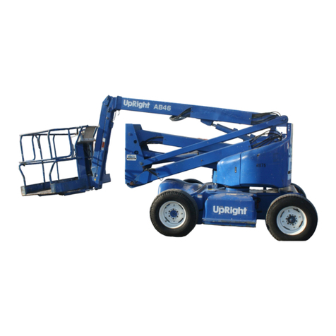
  9. Upright AB-46 Bi-Energy User manual

Upright AB-46 Bi-Energy User manual

Other manuals for AB-46 Bi-Energy

4

Other Upright Lifting System manuals

Upright LX Electric User manual

Upright

Upright LX Electric User manual

Upright SL-26 Guide

Upright

Upright SL-26 Guide

Upright MX19 User manual

Upright

Upright MX19 User manual

Upright X20N User manual

Upright

Upright X20N User manual

Upright AB-46 Bi-Energy User manual

Upright

Upright AB-46 Bi-Energy User manual

Upright MX15 User manual

Upright

Upright MX15 User manual

Upright LX31 User manual

Upright

Upright LX31 User manual

Upright ab62 User manual

Upright

Upright ab62 User manual

Upright AB-46 Bi-Energy User manual

Upright

Upright AB-46 Bi-Energy User manual

Upright X26 Ultra Narrow User manual

Upright

Upright X26 Ultra Narrow User manual

Upright AB38 Guide

Upright

Upright AB38 Guide

Upright X Series Guide

Upright

Upright X Series Guide

Upright POWERED ACCESS TL34 User manual

Upright

Upright POWERED ACCESS TL34 User manual

Upright ULII-25 Guide

Upright

Upright ULII-25 Guide

Upright MX19 Building instructions

Upright

Upright MX19 Building instructions

Upright LX31 User manual

Upright

Upright LX31 User manual

Upright SL20 Series User manual

Upright

Upright SL20 Series User manual

Upright AB-46 Bi-Energy User manual

Upright

Upright AB-46 Bi-Energy User manual

Upright MX15 User manual

Upright

Upright MX15 User manual

Upright SL26SL User manual

Upright

Upright SL26SL User manual

Upright ab62 User manual

Upright

Upright ab62 User manual

Upright SB60 Guide

Upright

Upright SB60 Guide

Upright LX31 User manual

Upright

Upright LX31 User manual

Upright SB-80 User manual

Upright

Upright SB-80 User manual

Popular Lifting System manuals by other brands

probst SDH-H-15 operating instructions

probst

probst SDH-H-15 operating instructions

Bruno OUTDOOR ELITE CRE-2110E Operator's manual

Bruno

Bruno OUTDOOR ELITE CRE-2110E Operator's manual

matev FPS Mounting Assembly Installation Guide

matev

matev FPS Mounting Assembly Installation Guide

Vestil CYL-HLT Series instruction manual

Vestil

Vestil CYL-HLT Series instruction manual

Butts Tools BXS0002 operating instructions

Butts Tools

Butts Tools BXS0002 operating instructions

Safelift MoveAround MA60 Original instructions

Safelift

Safelift MoveAround MA60 Original instructions

Terex Genie Z452513A-48153 Service and repair manual

Terex

Terex Genie Z452513A-48153 Service and repair manual

Granberg InDIago 510 Operating and care instructions

Granberg

Granberg InDIago 510 Operating and care instructions

EUFAB Bike Lift operating instructions

EUFAB

EUFAB Bike Lift operating instructions

morse 82H-124 Operator's manual

morse

morse 82H-124 Operator's manual

Braun NL955 Series Operator's manual

Braun

Braun NL955 Series Operator's manual

Protekt AT 252 instruction manual

Protekt

Protekt AT 252 instruction manual

R. Beck Maschinenbau HS 600 operating manual

R. Beck Maschinenbau

R. Beck Maschinenbau HS 600 operating manual

Nova Technology International, LLC NAS Series quick start guide

Nova Technology International, LLC

Nova Technology International, LLC NAS Series quick start guide

Genie Z-60/34 Operator's manual

Genie

Genie Z-60/34 Operator's manual

Screen Technics INTERFIT Vertical Up Lift instructions

Screen Technics

Screen Technics INTERFIT Vertical Up Lift instructions

Drive DUPONT SAMERY Hermes user manual

Drive

Drive DUPONT SAMERY Hermes user manual

Custom Equipment Hy-Brid 3 Series MAINTENANCE & TROUBLESHOOTING MANUAL

Custom Equipment

Custom Equipment Hy-Brid 3 Series MAINTENANCE & TROUBLESHOOTING MANUAL

manuals.online logo
manuals.online logoBrands
  • About & Mission
  • Contact us
  • Privacy Policy
  • Terms and Conditions

Copyright 2025 Manuals.Online. All Rights Reserved.

44
FOR MORE INFORMATION
USA Local Distributor:
TEL: (1) 209-891-5200
FAX: (1) 209-896-9012
PARTSFAX: (1) 209-896-9244
1775 Park St., Se ma, CA 93662
http://www.upright.com
EUROPE
TEL: (353) 1-202-4100
FAX: (353) 1-285-1710
Pottery Road, Dun Laoire, Ire and
ÉTATS-UNIS Distributeur local :
TÉL. : (1) 209-891-5200
TÉLÉC. : (1) 209-896-9012
TÉLÉC. (PIÈCES) : (1) 209-896-9244
1775 Park St., Se ma, CA 93662
http://www.upright.com
EUROPE
TÉL : (353) 1-202-4100
TÉLÉC. : (353) 1-285-1710
Pottery Road, Dun Laoire, Ire and
USA Inr Ortsveitrieb:
TEL: (1) 209-891-5200
FAX: (1) 209-896-9012
Fax für Ersatztei e: (1) 209-896-9244
1775 Park St., Se ma, CA 93662
http://www.upright.com
EUROPA
TEL: (353) 1-202-4100
FAX: (353) 1-285-1710
Pottery Road, Dun Laoire, Ire and
USA Distribudor local:
TÉLÉFONO: (1) 209-891-5200
FACSÍMIL : (1) 209-896-9012
FACSÍMIL PARA REPUESTOS: (1) 209-896-9244
1775 Park St., Se ma, CA 93662
http://www.upright.com
EUROPA
TÉLÉFONO: (353) 1-202-4100
FACSÍMIL : (353) 1-285-1710
Pottery Road, Dun Laoire, Ire and
068342-022
068342-022 4-98 D
1
Operator Manual
Guide de lutilisateur
Betriebsanleitung
Manual del operador
WARNING
All personnel shall carefully read, understand and follow all safety rules, and
operating instructions before performing maintenance on or operating any
UpRight aerial work platform.
AVERTISSEMENT
Tout le personnel doit lire attentivement et respecter toutes les consignes de
sécurité avant dentretenir ou dutiliser une plate forme élévatrice UpRight.
WARNUNG
Alle Bediener müssen die Sicherheitsregeln und Bedienungsanleitungen gründlich
durchlesen, verstehen und befolgen, bevor sie an irgendeiner UpRight Hocharbeitsbühne
Wartungsarbeiten ausführen oder diese in Betrieb nehmen.
ADVERTENCIA
Todo el personal debe leer atentamente, entender y respetar todas las reglas de
seguridad, las instrucciones de operación antes de efectuar trabajos de
mantenimiento o manejar cualquier plataforma aérea de trabajo UpRight.
Refer to page 2 for the English language version of this Operator Manual.
Reportez-vous à la page 12 pour la version française de ce manuel de lutilisateur.
ezüglich der deutschsprachigen Ausgabe dieser etriebsanleitung siehe Seite 22.
Referirse a la página 32 para la versión en español de este manual del operador.
AB-46 Bi-Energy
AB-46 Bi-Energy
SERIAL NO. 1000 TO CURRENT
2
English Language Section
NEVER operate the
machine within ten (10)
feet of power lines.
THIS MACHINE IS
NOT INSULATED.
NEVER operate
the boom or drive
with platform
elevated unless on
firm level surface.
NEVER position the
platform without first
checking for over-
head obstructions or
other hazards.
NEVER climb, stand
or sit on platform
guardrails or midrail.
Electrocution Hazard Tip Over Hazard Collision Hazard Fall Hazard
ALL occupants must wear an approved fall restraint properl attached to designated platform
anchorage point. Attach onl one fall restraint to each anchorage point.
NEVER exceed maximum platform load of 500 lbs. (225 kg) and two (2) occupants.
NEVER exceed 45 lbs. (200 N) of side force per occupant.
NEVER Operate the machine when noise levels exceed 80 dB.
DISTRI UTE all platform loads evenl on the platform.
NEVER operate the machine without first surve ing the work area for surface hazards such as
holes, drop-offs, bumps, curbs, or debris; and avoiding them.
OPERATE machine onl on surfaces capable of supporting wheel loads.
NEVER elevate the machine when wind speeds exceed 28 mph (12.5 m/sec.).
IN CASE OF EMERGENCY push emergenc stop button to cut power to all machine functions.
ALWAYS close and secure gate after entering platform.
NEVER exit or enter platform while elevated.
NEVER use ladders, scaffolding, or other items to gain height; work onl from the platform floor.
NEVER climb down elevating assembl while platform is elevated.
INSPECT the machine thoroughl for cracked welds, loose or missing hardware, h draulic leaks,
loose wire connections, and damaged cables or hoses before using.
VERIFY that all labels are in place and legible before using.
NEVER use a machine that is damaged, not functioning properl , or has damaged or missing
labels.
IF ALARM SOUNDS while boom is elevated, STOP, carefull retract boom and lower platform
without rotating. Move machine to a firm, level surface.
NEVER attach overhanging loads or use boom as a crane.
NEVER alter operating or safet s stems without manufacturers written consent.
NEVER charge batter near sparks or open flame. Charging batteries emit explosive h drogen
gas.
NEVER replace an component or part with an thing other than original UpRight replacement parts
without the manufacturer's written consent.
NEVER tow the machine. Transport b truck or trailer onl .
AFTER USE, secure the work platform from unauthorized use b turning both ke switches off and
removing all ke s.
SAFETY RULES
43
Notes:
42
YGRENE-IB64-BACITAMEHCSCILUARDYHTHGIRPU 300-04386.ONTRAP
HSILGNESIAÇNARFNAMREGHSINAPS
ISP057HCTIWSERUSSERP2op/bl057TATSONAMISP057retlahcskcrDISP057NOISERPEDROTPURRETNI
TFELEHCUAGsknilADREIUQZI
THGIRETIORDsthcerAHCERED
SEKARBSNIERFnesmerBSONERF
YLPPAEKARBSNIERFSEDEGARRESneheiznaesmerBONERFEDRACILPA
ESAELEREKARBSNIERFSEDEGARRESSEDnesölesmerBONERFEDRATLOS
KCOLBEVLAVEKARBNIERFEDEPAPUOSEDEGACOLBkcolblitnevsmerBONERFEDALUVLAVEDEUQOLB
ECIFIRO518518ECIFIRO518ednelB518OICIFIRO
TROPTSETIASSE'DESIRPßlhcsnafürPABEURPEDOTREUP
HGIHTUAHkcrdhcoHOTLA
WOLSABkcrdredeiNOJAB
PMUPEPMOPepmPABMOB
RENIARTSNOITCUSNOITARIPSA'DENIPÉRCbeisgasnANOICARIPSAEDORTLIF
RETLIFNRUTERRUOTEREDERTLIFretliffalkcüRONROTEREDORTLIF
MPG5.2nim/.lag5,2MPG5,2MPG5.2
REETSNOITCERIDgnkneLRIGIRID
RESIRTNEMEVÈLUOSEDÉLUCITRASARBkinahcembHRODAVELE
DNETXEMOOBEHCÈLFALEDTNEMEIOLPÉDnerhafsaregelsAAMULPREDNETXE
ESIARMOOBEHCÈLFALEDNOITAVÉLÉnebehregelsAAMULPRAVELE
BIJXUAF-À-ETROPNESARBmramrofttalPOZARB
RETSAMERTÎAMlitnevtpaHORTSEAM
EVALSEVALCSElitnevegloFOVALCSE
ETATOREGACALEDSPROC-EDRAGUDNOITATOR
EMROF-ETALP
neknewhcsbrokrhaFALUAJRATOR
WELSEUEUQ-À-ETETneknewhcSRATOR
LEVELMIRTETTEISSA'DUAEVINnereilleviNETSUJAEDLEVIN
FEILERHGIHEÉVELÉ,NOISSERPEDNOITCUDÉRgntsaltnekcrdhcoHOTLAOIVILA
PMUDHGIHÉVELÉ,TNEMEGRAHCÉDnessalbakcrdhcoHOTLAAGRACSED
ETARWOLTIBÉDELBIAFmasgnalOJABDADICOLEV
RETREVIDRUETITRAPÉRlitnevknelmURODAVIRED
PMUPDNAHNIAMÀEPMOPepmpdnaHLAUNAMABMOB
KCOLBEVLAVMOOBALEDEPAPUOSEDEGACOLB
EHCÈLF
kcolblitnevregelsAAMULPEDSALUVLAVEDEUQOLB
FEILERWOLESSAB,NOISSERPEDNOITCUDÉRgntsaltnekcrdredeiNOJABOIVILA
ETATORTERRUTREVLOVERUDNOITATORneknewhcslletsegherDERROTRATOR
3
Introduction
This manual covers the operation of electric powered
models of the AB-46 Articulated Boom. This manual
must be stored on the machine at all times.
Pre-Operation and Safety
Inspection
Carefully read, understand and follow all safety rules,
labels, and operating instructions, then perform the
following steps each 2 day before use.
Perform a complete visual inspection of the entire unit
prior to operating. Check the following areas for
discrepancies:
1. Open panels and check h draulic components /
hoses for damage or leaks. Check electrical
components / wiring for damage or loose
connections.
2. Inspect chassis, axles, hubs, and steering linkage
for damage, deformation, buckled paint, loose or
missing hardware, and cracked welds.
3. Check tires for damage, punctures, and inflation; tire
pressure must be 75 psi.
4. Check all hoses / cables for wear.
5. Inspect elevating assembl for damage, deformation,
buckled paint, loose or missing hardware, and
cracked welds.
6. Inspect platform and guardrails for damage,
deformation, buckled paint, loose or missing
hardware, and cracked welds. Insure that gate
operates freel and latches securel .
7. Check H draulic fluid level with platform full
lowered.
8. Check batter fluid level (see batter maintenance,
page 9).
9. Check fuel level, add fuel if necessar .
10. Ensure that radiator is cold, check coolant level. Add
if necessar .
Never remove the cap from a hot radiator. Hot
coolant can cause severe burns.
DO NOT use a machine that is damaged or
malfunctioning. Tag and remove the unit from
service until it is repaired.
SYSTEM FUNCTION INSPECTION
Note: Refer to figures 1 and 2 for chassis and
platform control locations.
1. Before performing the following tests, check area
around machine and overhead for obstructions,
holes, drop-offs, and debris.
2. Turn chassis ke switch to chassis, and turn on
(rotate clockwise) emergenc stop switches at the
chassis control panel and at the platform control
panel.
Note: The machine may be powered by batteries or
by engine. To power the machine by engine, press
the engine start button to crank the engine; release
when engine starts. If engine is cold: press the
preheat button and hold for six seconds prior to
starting diesel models.
3. Push in the chassis emergenc stop button and
operate an function switch at the chassis control
panel, function should NOT activate. Repeat for
platform emergenc stop button, operating chassis
controls. Return both emergenc stop switches to
the on position.
4. Operate each function switch to raise / lower, extend
/ retract, rotate left / right, each section of the
elevating assembl and observe the operation of the
machine. All functions should operate through full
c cle smoothl .
5. Turn chassis ke switch to platform.
6. Mount the platform, close and latch the gate, and
attach approved fall restraint to designated platform
anchorage point. Attach onl one fall restraint to each
point.
7. Without depressing the foot switch, move the drive
control handle, machine should not function.
8. Depress the foot switch and move the drive control
handle forward and reverse. Observe that
proportional functions operate smoothl , and that
brakes appl quickl after control is released.
9. While depressing foot switch, operate steer switch to
left and right. Observe that steering wheels turn
properl .
10. While depressing foot switch, turn function speed
control knob to desired setting, and operate boom
controls. Observe that boom operates smoothl ,
and that upper boom, jib, turret rotation, platform
level, and platform rotation controls operate
proportionall in conjunction with function speed
control knob. Observe that platform maintains level
when boom is elevated.
11. With the upper boom elevated one foot, operate drive
control handle. Observe that drive speed is limited
to creep (1/2 foot [.15 m] per second). Lower upper
boom to stowed position.
12. Press the service horn button. Observe that horn is
audible.

4
Operation
Before operating work platform insure that:
Pre-operation and safet inspection has been
completed, and an discrepancies have been
corrected.
The operator has been thoroughl trained on the
operation of the machine.
The work area is clear of all obstructions, holes,
drop-offs, or persons in the route of travel.
The surface is capable of supporting wheel loads.
Refer to figures one and two for control locations.
Emergency Stop
At an time during operation, press the emergenc stop
button to stop all functions in an emergenc .
Service Horn
At an time during operation, press the service horn
button to sound an audible warning if necessar .
Always wear an approved fall restraint properl
attached to designated platform anchorage point
when driving or elevating the machine (see figure 3).
Attach onl one fall restraint to each anchorage
point.
Figure 1: Chassis Controls
Note: The following list corresponds to the
numbered items in figures one and two.
1. Emergenc stop.
2. Diesel Engine start.
3. Glow Plug button.
4. Ke switch
5. Control fuses.
6. Riser control.
7. Upper boom control.
8. Boom extension control.
9. Jib control.
10. Turret rotation control.
11. Platform rotation control.
12. Platform level control.
13. Batter condition indicator & Hourmeter.
14. Service horn button.
15. Drive control handle.
16. Function speed control.
17. Foot switch (located on platform floor).
18. Out of level indicator.
19. Low Voltage indicator.
Controls and Indicators
Figure 2: Platform Controls Figure 3: Typical Fall Restraint Anchorage Point
1
45
6
7
8
9
10 11
12
13
23
14
9
5
6712
8
18
10
3
15
4
2
19
1
16
11
41
ÍTEM ESPECIFICACIÓN
Altura
Altura máxima de trabajo 16 m (52 pies)
Altura máxima de la plataforma 14 m (46 pies)
Paso en la plataforma en altura 2 cm (9 plg)
Altura superior 7,62 m (25 pies)
Altura en conducción 8 m (26 pies 9 plg)
Alcance horizontal 7,46 m (24 pies 6 plg)
Rotación de la torre 60 grados no continuos
Rotación de la plataforma 160 grados
Oscilación de la cola Ninguna
Longitud del brazo 1,52 m (5 pies)
Arco del brazo 140 grados
Radio de giro interno 61 cm (2 pies)
Radio de giro externo m (9 pies 10 plg)
Velocidad de conducción (reducida) 5,64 km/h ( ,5 mph)
Velocidad de conducción (elevada) 1 km/h (0,68 mph)
Gradabilidad 0%
Dimensiones (pluma recogida)
Tamaño de la plataforma 176 cm x 99 cm (69 x 9 plg)
Altura de la baranda 111 cm (4 ,5 plg)
Tabla de pie 15 cm (6 plg)
Capacidad máxima de la plataforma 226 kg (500 lbs)
Cantidad máxima de ocupantes 2
Peso 6,486 kg (14. 00 lbs)
Altura total 2 m (6 pies 6 plg)
Longitud total 5,4 m (17 pies 10 plg)
Ancho total 1,75 m (5 pies 9 plg)
Base de la rueda 185 cm (7 plg)
Banda de rodamiento de la rueda 150 cm (59 plg)
Terreno libre 5 cm (6 plg)
Fuente de energía Ochobater
í
as 6V, 50AH
Una Kubota 12 HP Diesel
Voltaje del sistema 48VDC
Presión hidráulica máxima 165 bar (2400 psi)
Controles Proporcional eléctrico
Neumáticos 9,5 x 16,5 con rodadura
para carreteras número 10
Especificaciones*
* Especificaciones sujetas a modificación sin aviso previo.
Ver información completa sobre componentes y mantenimiento en el Manual de
mantenimiento.
DIAGRAMA DE ALCANCE ENVOLVENTE
DIMENSIONES EN METROS
40
COMPONENTE INSPECCIÓN O MANTENIMIENTO INTERVALO S N R
Sistema de Control de funcionamiento de motores eléctricos Diario
propulsión Control de cables, contactos y conexiones Diario
eléctrica
Estructura Inspección de rajaduras estructurales Diario
de elevación Control de desgaste de pivotes 0D
Control torsión correcta de tornillo de retención de 0D
pasador de pivote
Control de deformación de partes Diario
Chasis Control de deformación o desgaste de mangueras Diario
Control de torsión correcta en montaje de 6M
componentes
Control de soldaduras resquebrajadas Diario
Torre Control de lubricación y desgaste de engranajes Diario
del anillo
Lubricación de cojinetes de engranaje helicoidal 150H/ M
Lubricación de engranajes del anillo (grasa MoS2) 150H/ M
Torsión Control de fugas Diario
Cubos de Control de nivel de aceite 250H/6M
las ruedas Cambio de aceite después de período de rotura 50H/ 0D
Cambio de aceite (aceite de engranajes SAE 90 wt.) 2000H/2A
Cilindros de Control de desgaste de las varillas del cilindro 0D
elevación Control de torsión correcta de tornillos de 0D
retención del pasador del pivote
Control de sellos por fugas 0D
Inspección de desgaste de pivotes 0D
Control de torsión correcta de conectores 0D
Unidad Control y reparación de daños por colisión Diario
Completa Control de torsión correcta de pasadores M
Control de corrosión, retirar y pintar M
Lubricación 0D
Etiquetas Control de estado, legibilidad o falta Diario
de etiquetas, reemplazar
Referencias de la Tabla de mantenimiento
de rutina
Intervalo
Diario = cada turno (todos los días) o cada ocho horas
30
D
= cada mes (30 días) o cada cincuenta horas
3
M
= cada 3 meses o cada 125 horas
6
M
= cada 6 meses o cada 250 horas
1
A
= cada año o cada 500 horas
2
A
= cada dos años o cada 1000 horas
S = Sí / aceptable
N = No / No aceptable
R = Reparada / Aceptable
Tabla de mantenimiento de rutina
Informe de mantenimiento
Fecha:
Propietario: _
Modelo No.: No. de serie:
Realizó mantenimiento:
Intervalo de mantenimiento:
MANTENIMIENTO DE RUTINA
Usar la tabla siguiente como guía para mantenimiento de
rutina. La inspección y el mantenimiento serán
realizados por personal entrenado y con experiencia
en mecánica y electricidad. Ver las instrucciones de
mantenimiento en el Manual de mantenimiento.
Fotocopiar esta página usar la Tabla de mantenimiento
de rutina como hoja de control al inspeccionar una
máquina.
COMPONENTE INSPECCIÓN O SERVICIOS INTERVALO S N R
Aceite del Control de nivel y estado Diario
motor Control de fugas Diario
Cambio de aceite y filtro 100HORAS
Systema de Control de nivel de combustible Diario
combustile Control de fugas Diario
Reemplazo de filtro de combustible 6M
Control de depurador de aire Diario
Refrigerante Control de nivel de refrigerante (con motor frío) Diario
del motor Reemplazo de refrigerante M
Sistema de Control de nivel de electrólito Diario
batería Control de gravedad específica 30
D
Limpieza exterior
M
Control del estado del cable de la batería Diario
Limpieza de terminales
M
Aceite Control de nivel de aceite Diario
hidráulico Cambio de filtro
6M
Drenaje y reemplazo con aceite compatible ISO 46
2A
Sistema Control de fugas Diario
hidráulico Control de conexiones de mangueras 0D
Control de desgaste exterior de mangueras 0D
Sistema Control de funcionamiento de anulador de Diario
hidráulico de emergencia válvulas y bomba manual
emergencia Control funcionamiento bomba manual de freno Diario
Controlador Control de funcionamiento de todos los controles Diario
Piso y rieles Control de torsión correcta de pasadores Diario
de la Control de soldaduras resquebrajadas Diario
plataforma Control del estado de la plataforma Diario
Control de estado de puntos de anclaje Diario
Control de estado del manual del operador Diario
Neumáticos Control de daños Diario
Control de presión de aire 5,1 bars (75 psi) Diario
Control tuercas de anillos de amarre
(torsión 12 Nm [90 pies libras]) 0D
Bomba Limpieza 0D
hidráulica Control de fugas en superficies de unión 0D
Control de fugas en accesorios de mangueras Diario
Control de torsión correcta en tornillos de montaje 0D
Sistema de Control de par de torsión en conectores 6M
dirección Engrasado de pivotes 0D
Control de péridas en cilindro de dirección 0D
Control de zonas de desgaste en en enlace 0D
Control de retenes flojos o faltantes Diario
5
Driving
With Boom Lo ered
1.
Turn chassis ke switch to platform, and turn on (turn
clockwise) the chassis emergenc stop switch.
2. Mount the platform, close and latch the gate.
3. Attach approved fall restraint to designated
platform anchorage point. Attach onl one fall
restraint to each point.
4. Check that the area around and above the work
platform is clear of obstructions, holes, drop-offs,
persons in the route of travel, and the surface is
capable of supporting wheel loads.
5. Depress the foot switch and move the drive control
handle forward to travel forward and reverse to travel
in the reverse direction.
Note: When the boom is rotated to the front of the
chassis (steering wheels aft) directions of travel and
steering will be reversed. Observe the color coded
arrows on the control panel near the drive control
handle, and on the chassis. They will indicate the
direction of travel when the drive control handle is
moved. Drive is disabled above 26 ft (8m).
With Boom Elevated
Travel with boom elevated is restricted to firm level
surfaces only.
When driving elevated, the machine will travel at creep
speed (½ foot [.15 m] per second).
Steering
1. While depressing the foot switch, push the steering
switch (located on top of the control handle) to the left
to turn left, and right to turn right.
Note: Steering is not self centering. Wheels must
be returned to the straight ahead position by
operating the steering switch.
POSITIONING THE PLATFORM
Positioning the platform as close as possible to the work
area requires some planning. First, ou must surve the
work site to find a suitable place to park the machine.
This must be a firm level area as close as possible to
the work area. Take into consideration all obstructions
on the ground and overhead and avoid them.
Once ou have moved the machine to a firm level
surface as near as possible to the work area, follow the
instructions on page 6 to position the platform.
Alwa s, before operating an function, check the area
around and overhead for an obstructions or electrical
conductors.
Multifunction Controls
The UpRight AB-46 emplo s the use of multifunction
controls. This means that riser or boom extension will
function at full speed while simultaneousl operating
upper boom, jib, turret, or rotating the platform.
The turret ma be rotated while driving if necessar to
make turns in tight areas. All other boom functions will
not operate while driving.
Lo er Control Operation
All boom functions will operate at fixed speed.
1. Turn chassis ke switch to chassis controls.
2. Operate boom control switches to position the
platform.
6
Elevating the Upper Boom
1. Set the function speed control dial to the desired
setting. Rotate the dial clockwise to increase speed,
counterclockwise to decrease. If ou are not sure
what speed to use, start out slow; the speed can be
varied while operating the function.
2.
While depressing the foot switch, push the upper boom
control lever forward to elevate the upper boom,
rearward to lower the upper boom. Release the control
lever to stop elevating / lowering.
Extending the Upper
Boom
1. While depressing the foot switch, push the boom
extension control lever rearward to extend the boom,
forward to retract the boom. Release the control
lever to stop extending / retracting. The boom
extension will function at a constant speed, function
speed control setting is not necessar .
Elevating the Jib
1. Set the function speed control dial to the desired
setting. Rotate the dial clockwise to increase speed,
counterclockwise to decrease. If ou are not sure
what speed to use, start out slow; the speed can be
varied while operating the function.
2. While depressing the foot switch, push the jib control
lever forward to elevate the jib, rearward to lower the
jib. Release the control lever to stop elevating /
lowering.
Rotating the Platform
1. Set the function speed control dial to the desired
setting. Rotate the dial clockwise to increase speed,
counterclockwise to decrease. If ou are not sure
what speed to use, start out slow; the speed can be
varied while operating the function.
2. While depressing the foot switch, turn the platform
rotation control switch counterclockwise to rotate
left, clockwise to rotate right. Release the switch to
stop rotation.
Leveling the Platform
DO NOT operate the machine if the platform
does not maintain level when elevated.
Note: Platform leveling can be performed only with
the boom stowed and should be done only to
calibrate the automatic leveling system.
1. Set the function speed control dial to the desired
setting. Rotate the dial clockwise to increase speed,
counterclockwise to decrease. If ou are not sure
what speed to use, start out slow; the speed can be
varied while operating the function.
2. While depressing the foot switch, push the platform
level control switch forward to swing the platform
upward, rearward to swing the platform downward.
Release the switch to stop leveling.
Rotating the Turret
1. Set the function speed control dial to the desired
setting. Rotate the dial clockwise to increase speed,
counterclockwise to decrease. If ou are not sure
what speed to use, start out slow; the speed can be
varied while operating the function.
2. While depressing the foot switch, turn the turret
rotation control switch counterclockwise to rotate
left, clockwise to rotate right. Release the switch to
stop rotation. Observe the area around the boom
when rotating the turret to avoid an obstructions.
Elevating the Riser
1. While depressing the foot switch, push the riser
control lever forward to elevate the riser, rearward to
lower the riser. Release the control lever to stop
elevating / lowering. The riser will function at a
constant speed, function speed control setting is not
necessar .
39
Mantenimiento
NEUMÁTICOS
La elección de los neumáticos puede afectar la
estabilidad de la máquina. Sólo usar los neumáticos de
UpRight, salvo autorización escrita del fabricante.
CARGA DE LA BATERÍA
Sólo cargar la batería en una zona bien
ventilada.
Peligro de mezcla de gases explosiva. Mantener
la batería lejos de chispas, llama o humo.
Usar siempre anteojos de seguridad al trabajar
con baterías.
El fluido de la batería es mu corrosivo. Lavar
bien los derrames de fluido con agua limpia.
Usar siempre baterías UpRight de repuesto o
aquéllas aprobadas por el fabricante que pesen
55 kg (120 lb) c/u.
Cargar la batería de la siguiente manera:
1. Verificar el nivel del fluido. Si el nivel de electrólitos
sobre las placas es inferior a 10 mm (
3
/
8
plg) sólo
agregar agua destilada limpia.
2. Verificar que el cargador de voltaje esté en el voltaje
correcto.
3. Conectar el conductor del cable de extensión (calibre
mínimo 12 (1,5 mm²) 15 m (50 pies) de longitud
máxima) a la ficha del cargador ubicada en la
abertura en la parte delantera del chasis (fig. 7).
Conectar el cable de extensión a una salida con
descarga a tierra de voltaje frecuencia adecuados.
4. El cargador se encenderá automáticamente.
5. Cuando la batería esté totalmente cargada, el
cargador se apagará automáticamente.
MANTENIMIENTO DE LA BATERÍA
Controlar diariamente el nivel del fluido, especialmente si
se usa la plataforma en clima seco cálido.
Si el nivel de electrólitos sobre las placas es inferior a
10 mm (
3
/
8
plg) sólo agregar agua destilada. NO usar
agua potable a que acorta la vida de la batería.
Mantener limpias las terminales la tapa de la batería.
ACEITE HIDRÁULICO
1. Con la plataforma totalmente baja, controlar el nivel
de aceite en el indicador que está dentro del
compartimento del motor, a la derecha.
2. Con la plataforma totalmente baja, controlar el nivel
de aceite en la varilla de nivel /o en el indicator que
está dentro del compartimiento del motor a la
izquierda.
3. Levantar la compuerta que está arriba del chasis, del
lado izquierdo.
4. Abrir la tapa de lienado respiración.
5. Tapar de nuevo.
LUBRICACIÓN
Ver cuadro de lubricación e instrucciones en el manual
de mantenimiento.
Figura 7: Cargador de la batería
Amperímetro
Cable AC
Figura 8: aterías (por lo general a ambos lados)
Desconexión
de batería
Figura 9: Tapa de llenado de aceite hidráulico,
entrada de combustible / tapa del respiradero y
respidrador e indicador de nivel deaceite
Indicador del nivel de aceite
Entrada de combustible /
tapa del respiradero
Tapa de llenado de aceite
hidráulico respirador
38
Transporte
POR GRÚA
Pararse lejos de la máquina cuando ésta es
levantada.
Ver las especificaciones en la última página,
controlar que la grúa las eslingas tengan la
capacidad adecuada para levantar el peso de la
unidad.
1. Verificar que la pluma esté totalmente baja
replegada.
2. Sólo colocar correas en los anillos de amarre del
chasis. Las correas deben estar bien ajustadas para
mantener la unidad nivelada al levantarla.
POR CAMIÓN O TRÁILER
1. Verificar que la pluma esté totalmente baja
retraida.
2. Colocar la máquina en el piso del camión o tráiler.
3. Para levantar la unidad seguir las instrucciones para
remolque de emergencia en la página 37. Colocar el
cable del cabrestante en los anillos de amarre
delanteros.
No levantar la máquina a una velocidad superior
a 5 km/h (3 millas por hora).
4. Después de levantar, verificar que estén colocados
los frenos.
5. Asegurar la máquina al vehículo de transporte
usando cadenas o correas de capacidad de peso
adecuadas en los anillos de amarre del chasis (ver
especificaciones en la última página) (ver fig. 6).
6. Colocar un bloque de madera de 19 cm x 10 cm x
71 cm (7,5 plg x 4 plg x 28 plg) debajo de las barras de
apo o de la plataforma como se muestra en la figura 6.
7. Colocar correa de trinquete debajo del enrejado del
piso de la plataforma, sobre las barras de apo o
(ver fig. 6). Asegurar sin ajustar demasiado.
NUNCA elevar la máquina cuando está en un
camión o tráiler.
Figura 6: Cómo asegurar la máquina para el traslado
Bloque de madera de
19 cm 10 cm 71 cm
(7,5 plg 4 plg 28 plg)
Anillas de amarre
para elevación
del chasis
7
EMERGENCY OPERATION
In the event of powered function failure, the elevating
assembl ma be lowered manuall b the following
procedure.
NEVER climb down the elevating assembl . If
controls do not respond, ask someone on the
ground to lower the boom manuall .
Lo ering Elevating Assembly
1. Open the cover on the h draulic module (opposite
side of the turret from the chassis control panel).
2. Remove the wire loop retainer from the hand pump
lever, and extend the handle upward to gain
leverage.
3. Operate the manual override (knurled knob) on the
appropriate valve (see fig. 4). Push in to lower /
extend, pull out to raise / retract as required.
4. While holding the appropriate valve in position, pump
the handle in and out until that section of the
elevating assembl is lowered / retracted.
5. Repeat as necessar operating each valve until the
elevating assembl is full lowered.
Rotating Turret
1. Obtain a
7
/
8
inch ratcheting wrench.
2. Place the socket of the wrench onto the hex shaft
stub of the turret rotation gearbox.
3. Turn the wrench clockwise to rotate the turret
counterclockwise, turn counterclockwise to rotate the
turret clockwise.
EMERGENCY TOWING
Perform the following onl when the machine will not
operate under its own power and it is necessar to move
the machine or when winching onto a trailer for
transportation.
The batteries must be connected to release the brakes.
1. Insure that the platform is full lowered, and that the
turret is rotated so the platform is to the rear of the
machine.
2. Attach chain / cable of sufficient strength for towing
the machine to front or rear tie down lugs.
3. Turn the ke switch to the parking brake release
position. Alarm will sound.
4. Operate the emergenc control pump four full
strokes to release brakes.
5. After moving the machine, return the ke switch to
the off position and remove the ke to prevent
unauthorized operation. Brakes are now reset. Alarm
will stop.
DO NOT move the machine faster than 3 mph.
Faster speeds will damage drive components
and void warrant .
AFTER USE EACH DAY
1. Ensure that the platform is full lowered.
2. Park the machine on level ground, preferabl under
cover, secure against vandals, children or
unauthorized operation.
3. Turn the ke switch to OFF and remove all ke s to
prevent unauthorized operation.
BATTERY CHARGING
See Maintenance, page 9.
Figure 4: Emergency Control Operation
Emergenc control pump
Riser Valve
Boom Valve
Extend Valve
Jib Valve
Figure 5: Manual Turret Rotation
7
/
8
in. Ratcheting
Wrench
Turret Rotation
Gear Box
8
Transportation
BY CRANE
Stand clear of machine when lifting.
Check specifications on back page, insure that
crane and slings are of correct capacit to lift
weight of unit.
1. Insure that boom is full lowered and retracted.
2. Attach straps to chassis lifting lugs onl . Insure that
straps are adjusted properl to keep unit level when
lifting.
BY TRUCK OR TRAILER
1. Insure that boom is full lowered and retracted.
2. Maneuver the machine onto bed of truck / trailer.
3. When winching, follow instructions for emergenc
towing on page 7. Attach winch cable to front tie
down lugs.
Do not winch machine faster than 3 mph.
4. After winching, insure that brakes are set.
5. Secure the machine to the transport vehicle using
chains / straps of adequate load capacit (refer to
specifications, back page) attached to chassis tie
down lugs (see figure 6).
6. Place a wooden block (7.5" x 4" x 28") under
platform support braces as shown (see figure 6).
7. Attach ratchet strap; under platform floor grating,
over support braces (see figure 6). Tighten securel ,
do not overtighten.
NEVER elevate the machine while on a truck or
trailer.
Figure 6: Securing the Machine for Transportation
Wooden Block
7.5" x 4" x 28"
Chassis Tie Down /
Lifting Lug (t p.)
37
OPERACIÓN DE EMERGENCIA
En el caso de fallas eléctricas, la estructura de
elevación puede bajarse manualmente con el siguiente
procedimiento.
NUNCA descender por la estructura de elevación.
Si los controles no responden, pedir a alguien que
desde el suelo baje la pluma en forma manual.
Cómo bajar la estructura de
elevación
1. Abrir la tapa del módulo hidráulico (en la torre,
opuesto al panel de control del chasis).
2. Retirar el retén del circuito de la palanca de la bomba
de mano extender el mango hacia arriba haciendo
palanca.
3. Usar el anulador manual (perilla estriada) en la
válvula correspondiente (ver fig. 4). Presionar para
bajar o extender, tirar para elevar o retraer segun sea
necesario.
4. Manteniendo en posición la válvula correspondiente,
mover el mango hacia adentro hacia afuera hasta
bajar o retraer esa sección del elevador.
5. Repetir en cada válvula las veces que sea necesario
hasta bajar toda la estructura
Rotación de la torre
1. Conseguir una llave de trinquete de
7
/
8
pulgadas.
2. Colocar la abertura de la llave en el muñón del eje
hexagonal de la caja de cambios de rotación.
3. Girar la llave en el sentido de las agujas del reloj la
torre rotará en sentido contrario. La torre rotará en el
sentido de las agujas del reloj al girar la llave en
sentido contrario a las agujas del reloj.
REMOLQUE DE EMERGENCIA
Sólo realizar este procedimiento cuando la máquina no
va a funcionar por sí misma es necesario moverla o
cargarla en un camión para transportarla.
La batería debe estar conectada para desenganchar los
frenos.
1. Verificar que la plataforma esté totalmente baja
que la torre esté rotada de manera que la plataforma
esté detrás de la máquina.
2. Colocar en los anillos de amarre delanteros o
traseros una cadena o cable resistente para remolcar
la máquina.
3. Poner el interruptor de llave en la posición
desenganchar freno de mano (parking brake release).
Sonará una alarma.
4. Operar la bomba de control de emergencia cuatro
veces para soltar los frenos.
5. Después de mover la máquina, volver el interruptor a
la posición apagado (off) retirar las llaves para
evitar el uso no autorizado. Los frenos a están fijos.
La alarma se detendrá.
NO mover la máquina a una velocidad ma or a
5 km/h (3 millas por hora). Velocidades ma ores
dañarán componentes de transmisión anularán
la garantía
DESPUÉS DE CADA USO DIARIO
1. Verificar que la plataforma esté totalmente baja.
2. Estacionar la máquina en terreno llano, de
preferencia bajo techo, protegida contra vándalos,
niños o usos no autorizados.
3. Apagar el interruptor sacar la llave para evitar usos
no autorizados.
CARGA DE LA BATERÍA
Ver Mantenimiento, página 39.
Figura 4: Operación de control de emergencia
Bomba de control
de emeregencia
Válvula de la
pluma
Válvula del
e tensión
Válvula del
elevador
Válvula
del brazo
Figura 5: Rotación manual de la torre
Llave de trainquete
de
7
/
8
pulgadas
Caja de cambios
de la rotación
de la torre
36
Nivelación de la
plataforma
NO usar la máquina si la plataforma no se
mantiene nivelada al elevarla.
Nota: La nivelación de la plataforma sólo se puede
efectuar con la pluma encogida y sólo debe hacerse
para calibrar el sistema de nivelación automático.
1. Colocar el selector de velocidad en el punto
deseado. Rotar el selector en el sentido de las
agujas del reloj para incrementar la velocidad en
sentido inverso para disminuirla. Si no se tiene
certeza acerca de qué velocidad usar, empezar
lento; la velocidad puede variarse mientras se usa la
función.
2. Al tiempo que se presiona el cambio de pie,
presionar hacia adelante el control del nivel de la
plataforma para elevarla hacia atrás para bajarla.
Soltar el control para dejar de nivelar.
Rotación de la torre
1. Colocar el selector de velocidad en el punto
deseado. Rotar el selector en el sentido de las
agujas del reloj para incrementar la velocidad en
sentido inverso para disminuirla. Si no se tiene
certeza sobre qué velocidad usar, empezar lento; la
velocidad puede variarse mientras se usa la función.
2. Al tiempo que se presiona el cambio de pie, girar el
control de rotación de la torre en el sentido de las
agujas del reloj para rotar a la derecha en sentido
inverso para rotar a la izquierda. Soltar el control
para dejar de rotar. Examinar la zona al rotar la torre
para evitar obstáculos.
Cómo levantar el
elevador
1. Al tiempo que se presiona el cambio de pie, empujar
hacia adelante la palanca de control del elevador
para subirlo, hacia atrás para bajarlo. Soltar la
palanca de control para dejar de subirlo o bajarlo. El
elevador funcionará a una velocidad constante, no
es necesario determinar la velocidad.
Elevación de la pluma
superior
1. Colocar el selector de velocidad en el punto
deseado. Rotar el selector en el sentido de las
agujas del reloj para incrementar la velocidad en
sentido inverso para disminuirla. Si no se tiene
certeza sobre qué velocidad usar, empezar
lentamente; la velocidad puede variarse mientras se
usa la función.
2. Al tiempo que se presiona el cambio de pie, empujar
hacia adelante la palanca de control de la pluma
superior para elevarla hacia atrás para bajarla. Soltar
la palanca de control para dejar de elevar o bajar.
Extensión de la pluma
superior
1. Al tiempo que se presiona el cambio de pie, empujar
hacia atrás la palanca de extensión de la pluma
para extenderla hacia adelante para replegarla.
Soltar la palanca de control para dejar de extender o
replegar. La extensión de la pluma se realizará a una
velocidad constante, no es necesario determinar la
velocidad.
Elevación del brazo
1. Colocar el selector de velocidad en el punto
deseado. Rotar el selector en el sentido de las
agujas del reloj para incrementar la velocidad en
sentido inverso para disminuirla. Si no se tiene
certeza sobre qué velocidad usar, empezar
lentamente; la velocidad puede variarse mientras se
usa la función.
2. Al tiempo que se presiona el cambio de pie, empujar
la palanca de control del brazo hacia adelante para
elevarlo hacia atrás para bajarlo. Soltar la palanca
para dejar de elevar o bajar.
Rotación de la
plataforma
1. Colocar el selector de velocidad en el punto
deseado. Rotar el selector en el sentido de las
agujas del reloj para incrementar la velocidad y en
sentido inverso para disminuirla. Si no se tiene
certeza sobre qué velocidad usar, empezar
lentamente; la velocidad puede variarse mientras se
usa la función.
2. Al tiempo que se presiona el cambio de pie, girar el
control de rotación de la plataforma en el sentido de
las agujas del reloj para rotar hacia la derecha y a la
inversa para rotar a la izquierda. Soltar el control
para detener la rotación.
9
Maintenance
TIRES
Tire selection can affect the stabilit of the machine.
Use onl tires supplied b UpRight unless approved b
the manufacturer in writing.
BATTERY CHARGING
Charge batteries onl in a well ventilated area.
Hazard of explosive gas mixture. Keep sparks,
flame and smoking materials awa from
batteries.
Alwa s wear safet glasses when working with
batteries.
Batter fluid is highl corrosive. Rinse awa an
spilled fluid thoroughl with clean water.
Alwa s replace batteries with UpRight batteries
or manufacturer approved replacements weighing
120 lbs. each.
Charge batteries as follows:
1. Check the batteries fluid level. If the electrol te level
is lower than
3
/
8
in. (10 mm) above the plates, add
clean, distilled water onl .
2. Verif charger voltage switch is set to the correct
voltage.
3. Connect extension cord (minimum 12 gauge
(1.5 mm²) conductor and maximum 50 ft. (15 m) in
length) to charger plug located through the opening in
front of the chassis (see figure 7). Connect extension
cord to properl grounded outlet of proper voltage
and frequenc .
4. The charger will turn on automaticall .
5. When the batteries are full charged, the charger will
turn off automaticall .
BATTERY MAINTENANCE
Check batter fluid level dail , especiall if work platform
is being used in a warm, dr climate.
If electrol te level is lower than
3
/
8
in. (10 mm) above
plates add distilled water onl . DO NOT use tap water it
will shorten batter life.
Keep terminals and top of batter clean.
HYDRAULIC OIL
1. Check oil level at dipstick and/sight gauge inside
engine compartment right hand side with the platform
full lowered.
2. Lift flap located on top of chassis right side (see
figure 9).
3. Open filler / breather cap.
4. If necessar , fill to capacit with clean ISO 46
compatible h draulic oil.
5. Replace cap.
LUBRICATION
Refer to service manual for lubrication chart and
guidelines.
Figure 8: atteries (Typical oth Sides)
Batter Disconnect
Figure 7: attery Charger
Ammeter
AC Cord
Figure 9: Hydraulic Oil Filler / reather Cap, Fuel
Filler / reather Cap, and Oil Level Sight Gauge
Oil Level
Sight Gauge
Fuel Filler /
Breather Cap
H draulic Oil Filler /
Breather Cap
10
COMPONENT INSPECTION OR SERVICES INTERVAL Y N R
Electric Check electric drive motors for operation. Daily
Drive System Check cables, contactors and connections. Daily
Elevating Inspect for structural cracks. Daily
Assembly Check pivot points for wear. 0D
Check pivot pin retaining bolts for proper torque. 0D
Check members for deformation. Daily
Chassis Check hoses for pinch or rubbing points. Daily
Check component mounting for proper torque. 6M
Check welds for cracks. Daily
Turret Check ring gear for proper lubrication and wear. Daily
Lubricate worm gear bearings. 150H/ M
Lubricate ring gear (MoS2 grease). 150H/ M
Torque Check for leaks. Daily
Hubs Check oil level. 250H/6M
Change oil after break-in period. 50H/ 0D
Change oil (SAE 90 wt. gear oil). 2000H/2Y
Lift Check the cylinder rods for wear. 0D
Cylinders Check pivot pin retaining bolts for proper torque. 0D
Check seals for leaks. 0D
Inspect pivot points for wear. 0D
Check fittings for proper torque. 0D
Entire Check for and repair collision damage. Daily
Unit Check fasteners for proper torque. M
Check for corrosion, remove and repaint. M
Lubricate. 0D
Labels Check for peeling, missing, or unreadable Daily
labels & replace.
COMPONENT INSPECTION OR SERVICES INTERVAL Y N R
Engine Oil Check level and condition. Daily
Check for leaks. Daily
Change oil & filter 100HOURS
Engine Fuel Check fuel level. Daily
System Check for leaks. Daily
Replace fuel filter. 6M
Check air cleaner. Daily
Engine Check coolant level (with engine cold). Daily
Coolant Replace coolant. M
Battery Check electrolyte level. Daily
System Check specific gravity. 0D
Clean exterior. M
Check battery cable condition. Daily
Clean terminals. M
Hydraulic Check oil level. Daily
Oil Change filter. 6M
Drain and replace with ISO 46 compatible oil. 2Y
Hydraulic Check for leaks. Daily
System Check hose connections. 0D
Check hoses for exterior wear. 0D
Emergency Check operation of emergency override Daily
Hydraulic valves and hand pump.
System Check operation of brake release hand pump. Daily
Controller Check operation of all controls. Daily
Platform Check fasteners for proper torque. Daily
Floor and Check welds for cracks. Daily
Rails Check condition of platform. Daily
Check condition of anchorage points. Daily
Check condition of operators manual. Daily
Tires Check for damage . Daily
Check air pressure (75 psi). Daily
Check lug nuts (torque to 12 Nm [90 ft. lbs.]). 0D
Hydraulic Wipe clean. 0D
Pump Check for leaks at mating surface. 0D
Check for hose fitting leaks. Daily
Check mounting bolts for proper torque. 0D
Routine Service Table Key
Interval
Dail = each shift (ever da ) or ever eight hours
30
D
= ever month (30 da s) or ever 50 hours
3
M
= ever 3 months or 125 hours
6
M
= ever 6 months or 250 hours
1
Y
= ever ear or 500 hours
2
Y
= ever 2 ears or 1000 hours
Y = Yes / Acceptable
N = No / Not Acceptable
R = Repaired / Acceptable
Routine Service Table
Service Report
Date: ________________________________________
Owner: ______________________________________
Model No: ___________ Serial No: _______________
Serviced B : _________________________________
Service Interval: _______________________________
ROUTINE SERVICE
Use the following table as a guide for routine
maintenance. Inspection and maintenance shall be
performed by personnel who are trained and familiar
with mechanical and electrical procedures. Refer to
the Service Manual for complete service instructions.
Please cop this page and use the Routine Service
Table as a checklist when inspecting a machine for
service.
35
Conducción
Con la pluma baja
1. Poner el interruptor del chasis en plataforma
(platform) encender (girar en el sentido de las
agujas del reloj) el interruptor de parada de
emergencia del chasis.
2. Montar la plataforma, cerrar trabar la puerta.
3. Colocar el sujetador en el punto de anclaje indicado
en la plataforma. Colocar un solo sujetador en cada
punto.
4. Verificar que la zona el espacio aéreo de la
plataforma de trabajo estén libres de obstrucciones,
ho os, desniveles, personas en el recorrido que la
superficie sea capaz de soportar la carga de las
ruedas.
5. Presionar el cambio de pie mover la palanca de
conducción hacia adelante para avanzar hacia
atrás para retroceder.
Nota: Cuando se rota la pluma hacia el frente del
chasis (ruedas de dirección hacia atrás) el sentido
del desplazamiento y la dirección se invertirán. Mirar
las flechas de colores en el panel de control cerca de
la palanca de conducción y en el chasis. Cuando se
mueva la palanca de conducción las flechas
indicarán el sentido de desplazamiento. El
desplazamiento se desactiva arriba de los 8 metros
(26 pies).
Con la pluma levantada
El desplazamiento con la pluma levantada está
restringido a superficies llanas y firmes solamente.
Con la pluma levantada la máquina se moverá
lentamente (0,15 m [½ pie] por segundo).
Dirección
1. Al presionar el cambio de pie, presionar el cambio de
dirección (ubicado arriba de la palanca de control) a
la izquierda para doblar a la izquierda a la derecha
para doblar a la derecha.
Nota: La dirección no es autocentrante. Las ruedas
deben enderezarse nuevamente usando el cambio de
dirección.
UBICACIÓN DE LA PLATAFORMA
Ubicar la plataforma lo más cerca posible del área de
trabajo requiere preparación. Primero, ha que
inspeccionar la zona para encontrar un lugar adecuado
para estacionar la máquina. Debe ser una zona llana
firme, lo más cerca posible del área de trabajo. Tener en
cuenta todos los obstáculos aéreos en el terreno
evitarlos.
Una vez que se ha colocado la máquina en un lugar llano
firme lo más cerca posible del área de trabajo, seguir
las instrucciones en la página 36 para ubicar la
plataforma.
Antes de utilizar cualquier función siempre verificar la
presencia de obstrucciones o conductores eléctricos en
la zona aledaña.
Controles multifunción
El equipo UpRight AB-46 tiene controles multifunción,
esto significa que el elevador o la extensión de la pluma
funcionarán a máxima velocidad, al mismo tiempo que
está funcionando la pluma superior, el brazo, la torre o
se está rotando la plataforma.
Se puede rotar la torre durante la conducción si es
necesario girar en zonas angostas. Las demás funciones
de la pluma no funcionarán durante la conducción.
Operación de controles inferiores
Todas las funciones de la pluma actuarán a una
velocidad fija.
1. Girar el interruptor del chasis a controles del chasis
(chassis controls).
2. Accionar los controles de la pluma para ubicar la
plataforma.