Ushio PLUS -E User manual

Mold Protector
PLUS - E
PE-700
Operation Manual
Ver. 0.01
2021 OCTOBER
Ushio Lighting, Inc.

1
Introduction
Thank you for purchasing Ushio Lighting’s Mold Protector PLUS-E PE-700. This manual
describes the functions and how to operate it.
Please read this manual before using PE-700, to make optimum use of its functions and features.

2
Warning
1. Do not use this device in a place where there is flammable or explosive gas.
It is extremely dangerous, as sparks from the power switch may cause a fire.
2. Do not use forcibly bend the cable or place heavy things on it.
It will damage the cable, and may cause a fire or electric shock.
Caution
1. Avoid using the device in a place under direct sunlight, near a heat source, or where
it may be vibrated or hit. The ambient temperature should be between 0°C and 45°C,
and the relative humidity should be 85% or less where this device is used.
*Make sure there is no condensation.
2. Use the packing material that surrounded the device when it was delivered to transport
it somewhere.
3. Store it in a dry place, not under direct sunlight.
4. Turn off the power in the following cases. It may cause a breakdown or fire if used in
an abnormal state.
・If the device cannot be restored from an abnormal state.
・If a strange smell, smoke or strange sound is coming from the device.
・If foreign matter such as metal pieces or water has gone into the device or in gaps.
5. Do not take this device apart. It may cause a breakdown or fire.
Some of the descriptions in this operation manual may be different from the actual device. Please
note that the device specification is subject to change without notice. Your understanding is
appreciated.

3
CONTENTS
Introduction …………………………………………………………………1
Warning and Caution ………………………………………………………2
Chapter 1 Description of Components ………………………………. 4
1-1 Components ……………………………………………………………………. 4
1-1-1 Structure of Standard Set Parts ……………………………………………… 4
1-1-2 Optional Parts (Sold Separately) ……………………………………………. 5
1-2 Connection with I/O Unit and Camera………………………………………6
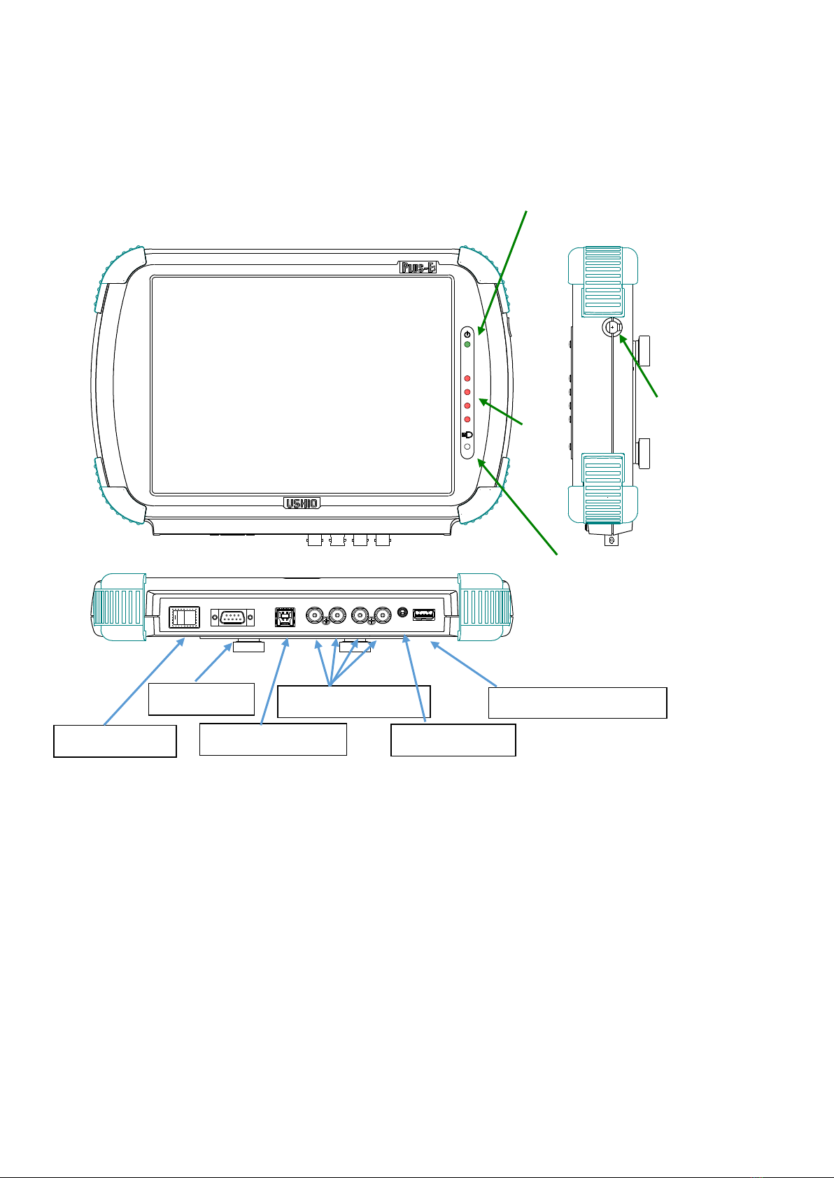
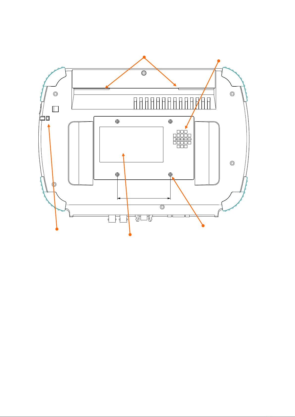
1-3 Structure of Main Unit ………………………………………………………….7
1-4 I/O Unit ………………………………………………………………………….9
1-5 I/O Cable ……………………………………………………………………….10
Chapter 2 Basic Operation ……………………………………………12
2-1 Power On and Initial Screen ………………………………………………….12
2-2 Main Men u ………………………………………………………………13
2-3 Setup Preference …………………………………………………………….14
2-4 System Setting ………………………………………………………………….18
2-5 Area Setup ………………………………………………………………………25
2-5-1 Area Setup (Advanced Setting : Off) …………………….………..…………25
2-5-2 Area Setup (Advanced Setting : On) ……………….………..…………………32
2-6 Reference Image Capture …………………………………………………….33
2-7 How to Test Monitoring ………………………………………………………. 40
2-8 How to Monitor …………………………………………………………………42
2-9 How to Use USB memory ……………………………………………………….50
2-10 How to Display the Log ……………………………………………………….55
2-11 Camera Connection ……………………………………………………………57
Chapter 3 Device Specification ………………………………………….58
3-1 Device Specification …………………………………………………………….58
3-2 Signal Time Chart …………………………………………………………………59
3-3 Interface Circuit ………………………………………………………………… 60
Chapter 4 Warranty Condition …………………………………………61

4
Chapter 1 Description of Components
1-1 Components
1-1-1 Structure of Standard Set Parts
①PE700 Main Unit
1
Main monitoring device
②Camera
1
Standard CMOS camera (Lens is option)
③Magnetic camera
stand
1
Magnetic camera stand.
Camera platform (to fix camera to the stand) is attached
④I/O unit
1
Unit to link input/output signals between the main unit and the
molding machine
⑤Camera cable
1
BNC cable to connect the main unit to the camera
⑥IF cable
1
Cable to connect the main unit to the I/O unit
⑦I/O Cable
4
Cable to connect the I/O unit to the molding machine
⑧Magnet catch
4
Magnetic screws to fix the main unit on the molding machine.
⑨Lighting Stand set
1
Magnetic Stand with a lighting set (Lamp is option )
⑩Operation pen &
cord
1
A touch panel pen.
It is accommodated to a hole at the side of the main unit
Standard Parts
⑤Camera Cable
②Camera
⑪Lens(Option)
③Magnetic Camera Stand
④I/O Unit
①PE-700 Main Unit
⑥IF Cable
⑦I/O Cable
⑧Magnet Catch

5
1-1-2 Optional Parts (Sold Separately)
⑪Lens
Lens for CMOS camera
⑫LED lamp
High Intensity LED lamp to illuminate the monitoring target.
⑬Infrared (IR) LED
lamp
Infrared LED lamp is to irradiate Infrared light to the monitoring target.
The camera with IR filter catches the infrared light reflected from the
monitoring target. IR light is featured to reduce the influence by ambient
light. (To illuminate wider area, Infrared LED floodlight is also available.)
⑭IR Filter
IR Filter placed on the lens cuts the visible light and enables to monitor
the infrared light. It reduces the influence by the ambient light, and
increases the recognition to black and grey color.
⑮Additional camera
set
② camera ⑤ camera cable and ⑪ lens are one set.
(This set is for monitoring with more than 2 cameras )
⑯Wide lens
It enables to shoot wider area.
⑰Zoom lens
It enables to zoom in the imaging area
⑱USB memory
USB memory is to record the NG image
⑫LED lamp + Magnetic Stand ⑬ Infrared LED lamp + Magnetic Stand
(Illuminate with 3000K warm light) (The center of bulb turns on with red color)

6
1-2. Connection of I/O Unit and Camera
The procedure to connect the device is shown in the figure below.
(Also see the Parts figure on page 5.)
P L U S - E
M O L D MA C H I N E
PLUS-EI/OUNIT
Note 1.Four cameras are used in the above figure.
(The 2nd to 4th cameras, lens, magnetic stand and camera cables are option.)
Note 2. The camera is recognized when power is turned on. Connect the camera cable before
switching the power on.
Note 3. Connect I/O cables (total of 4) from the I/O unit to each circuit of the molding machine.
Note 4. Connect the IF cable from the main unit to the I/O unit.
Note 5. Connect the camera cable from the main unit to the camera.
Camera cable
Camera
IF cable
I/O unit
I/O cable 4
I/O cable 3
I/O cable 2
I/O cable 1
To Injection
Molding Machine

7
1-3. Structure of Main Unit
PE-700 FRONT
US B 3I/ OPO W ER CO M U SB_M E M
CA M ERA4CA M ERA3CA M ERA2CA M ERA1
POWER LED (green) : Lights up when the power is on.
WATCH LED (red) :Lights up while monitoring.
Power Switch : Press the ““mark to turn on the power.
IF Connector : To connect the IF cable. Connect it to the I/O unit.
Camera 1/2 Connector : To connect the camera cable.
Camera 3/4 Connector : To connect the camera cable.
USB 3.0 Connector : To connect USB 3.0 device
USB memory Connector : Insert USB memory. (Power voltage: 5.0V)
USB memory LED : Lights up when the USB memory is read or being written.
Note : Do not pull out the USB memory while the LED light is on.
COM Connector : It is a connector for testing.
10.4-inch touch panel display
①POWER LED
②WATCH LED
Hole to
accommodate
touch pen
⑨USB memory LED
③Power Switch
④IF connector
⑦USB 3.0 connector
⑤⑥Camera connector
⑩COM connector
⑧USB memory connector

8
PE-700 Back
Fan vent : Vent for heat radiation.
Name plate : Serial number is written here.
Touch Pen Holder : A place to hook a cord for the touch pen.
Magnetic Screws Bracket : Place a magnet screws, a washer and a lubber cover.
75□
⑪ Fan vent
⑫ Name plate
Hook insert hole
⑭ Magnetic Screws Bracket
(For fixing 4-M4 tap)
⑬ Touch Pen Holder

9
1-4. I/O Unit
The specification of I/O unit is same as PE500 and PE600.
PL US- E
MOLD MACHINE
PLUS-E I/O UNIT
POWER LED : Lights up when the power is turned on.
IF connector : To connect the IF cable from the main unit.
I/O connector : 6-pin, 8-pin or 10-pin connector to connect to the molding machine
with using I/O cables 1, 2 and 3.
I/O connector : 10-pin connector. Connect it to the molding machine with using I/O cable 4.
①Power LED
② IF Cable Connector
③ I/O cable connector
④ I/O cable connector

10
1-5. I/O Cable
There are four I/O cables in total. Connect the connector side to the I/O unit, and the Y terminal
side to the internal circuit of the molding machine.
[Input / output signal rating]
Input signal : Non-voltage contact signal. (10KΩ pull-up to +24V power in the receiving circuit.)
Output signal : Semiconductor relay contact output.
※Contact allowable voltage: ±50V, contact allowable current : ±200mA
(However, ±50V, ±1000mA for Cycle Interlock and Eject Interlock)
I/O Cable Signal Specifications
It is possible to re-combine the connection counterpart with “Input signal connection setup” and
“output signal connection setup” for input signals and output signals. However, the following table
shows the status of “default” setup (without re-combination).
I/O Cable 1
Pin no.
Core wire
identification
color
Signal line type
Signal name
(Indicates the case
without signal re-combination)
Mark tube
characters
1
Red
AWG22
twisted pair line
OUT1
(Cycle interlock output)
A1
2
White
A2
3
Yellow
AWG22
twisted pair line
OUT3
(Eject interlock output)
C1
4
White
C2
5
Orange
AWG22
twisted pair line
OUT4
(Re-eject / Skip output)
D1
6
White
D2
7
Green
AWG22
twisted pair line
IN1
(Mold opening input)
H1
8
White
H2
9
Blue
AWG22
twisted pair line
IN2
(Eject complete signal)
J1
10
White
J2
I/O Cable 2
Pin no.
Core wire
identification
color
Signal line type
Signal name
(Indicates the case
without signal recombination)
Mark tube
characters
1
Brown
AWG22
twisted pair line
OUT2
(Take-out Robot start output)
B1
2
White
B2
3
Black
AWG22
twisted pair line
OUT6
(Monitoring /Cycle start output)
F1
4
White
F2
5
Grey
AWG22
twisted pair line
OUT7
(Reject defective product)
G1
6
White
G2
7
Pink
AWG22
twisted pair line
IN3
(Input alarm off)
K1
8
White
K2

11
I/O Cable 3
Pin no.
Core wire
identification
color
Signal line type
Signal name
(Indicates the case
without signal recombination)
Mark tube
characters
1
Purple
AWG22
twisted pair line
OUT5
(Output external alarm)
E1
2
White
E2
3
Red
AWG22
twisted pair line
+24V
24V
4
Black
GND
GND
5
Black
AWG22
Case earth
EARTH
6
NC (not connected)
I/O Cable 4
Pin no.
Core wire
identification color
Signal line type
Signal name
(Custom mode signal CM)
(Indicates the case
without signal recombination)
Mark
tube
characte
rs
10
Brown
AWG22
twisted pair line
IN4
(Spare for Input)
L1
5
Pink
L2
9
Red
AWG22
twisted pair line
IN5
(Input 1 for mold switching)
M1
4
Pink
M2
8
Orange
AWG22
twisted pair line
IN6
(Input 2 for mold switching)
N1
3
Pink
N2
7
Yellow
AWG22
twisted pair line
IN7
(Molding machine automatic input)
P1
2
Pink
P2
6
Green
AWG22
twisted pair line
IN8
(Input error off )
Q1
1
Pink
Q2

12
Chapter 2 Basic Operation
2-1. Power On and Initial Screen
①When power is turned ON, the Initial Screen (Image 1) is displayed. Select the display
language.
②Touch the “USHIO” logo in the center. If it is in manual run mode, the molding machine
interlock signal is released, and the main menu (Image 3) is displayed.
(Image 1) Initial Login
(Image 2) Device Information Display
USB memory property
Capacity property
This is displayed only if the
USB memory is inserted.
The yellow bar shows the used
capacity in the USB memory.
When the USB memory is
being accessed, it is displayed
in red.
Display of
device serial number,
software version, and clock
When you touch anywhere
other than the USHIO logo,
this is displayed at the
bottom.

13
2-2. Main Menu
(Image 3)
Main Menu (Image 3)
Setup Preference
Set the basic settings for monitoring.
・Select the Camera No.(Camera1, Camera2, Camera3, Camera4)
・Setup the monitoring method(Inspection 1, Inspection 2)
・Setup the pre-check, timer, Run (Molding) Machine without monitoring,
Reference image capture, Save NG image in USB memory, Save log file
System
Setup the basic system
Setup volumes, display setting, adjustment of mold position / error delete
option, password setting, clock, settings for signals
USB Memory
Setup for USB memory when it is inserted.
LOG
Display the log file and write a log file into the USB memory
Area Setup
Setup the monitoring area
Reference Image
Capture
Capture the reference image (standard image) for inspection process.
Start Monitoring
Starts monitoring.
Test Monitoring
Starts the monitoring test.
* When you select an option on the display, the button changes to light-blue color.
** If you touch the button and it is not selected, it means the option is disabled.
*** When you select the “Menu” button, it goes back to the Main Menu.

14
2-3. Setup Preference
Select Setup Preference in the Main Menu (Image 3).
①Setup the monitoring method of camera 1 & 2.
Monitoring method : setup which camera to use for which inspection.
(Image 4-1) Setup Preference Page 1/3 [Selected buttons are colored in a light-blue]
Inspection 1
Checks the molded products are in the mold before they drop.
Inspection 2
Checks the molded products completely drop off or taken by a take-
out robot.
Auto Mark
Only monitoring automatically detected area.
Whole Area
Monitoring the whole area specified by a user.
Camera designation
Setup the monitoring from color, monochrome, or IR (infrared)
monitoring for Camera 1 and Camera 2.
Displays the camera image as a color image.
When you touch the button, the screen is switched to
monochrome monitoring.
Displays the camera image as a monochrome image.
When you touch the button, the screen is switched to IR
monitoring.
Displays the camera image as an IR monochrome image.
When you touch the button, the screen is switched back to
color monitoring.

15
②Setup the monitoring method of camera 3 & 4.
(Image 4-2) Setup Preference Page 2/3
Inspection 1
Checks the molded products are in the mold before they drop.
Inspection 2
Checks the molded products completely drop off or taken by a take-
out robot.
Auto Mark
Only monitoring automatically detected area.
Whole Area
Monitoring the whole area specified by a user.
Camera designation
Setup the monitoring from color, monochrome, or IR (infrared)
monitoring for Camera 3 and Camera 4.
Displays the camera image as a color image.
When you touch the button, the screen is switched to
monochrome monitoring.
Displays the camera image as a monochrome image.
When you touch the button, the screen is switched to IR
monitoring.
Displays the camera image as an IR monochrome image.
When you touch the button, the screen is switched back to
color monitoring.

16
③ Setup the timer 1 and 2, and other setups
(Image 5)Setup Preference Page 3/3 (Image 6) Keypad
<Setup for Timer 1 and 2 >
1. Touch the Timer display part (unit : seconds).
2. Input the time by seconds in the keypad screen (Image 6) and press ENT to confirm.
3. Select whether the monitoring time should be shortened or not, with Wait Time OFF or ON.
Note 1. The waiting time becomes effective with Wait Time OFF.
During Wait Time On, the monitoring is repeated with no waiting time. When the
monitoring judges OK, the monitoring goes to the next process. When it reached to
the time set in the timer without acquiring “OK”, the monitoring judges NG.
Note 2. Timer 1 is the waiting time from mold open complete to inspection image 1 is captured.
When the time display button is touched, the keypad is displayed. Input the number
for the timer and touch ENT to confirm. You can set any number between 0 to 99.99
seconds by 0.01 seconds.
Note 3. Timer 2 is the waiting time from mold open complete or eject complete to the
Inspection 2 is captured. Set it up with the same way as the Timer 1.
Note 4. Wait Time On of Timer 2 is selectable when “Eject Complete Signal” setting is set
“On” in the System Setting page 3/3. (Refer to this manual page 20)

17
(Image 5) Setup Preference 3/3
Timer 1
Waiting time from mold open complete to inspection image 1 is
captured. (Unit : seconds)
Timer 2
Waiting time from mold open complete or eject complete to
inspection image 2 is captured. (Unit : seconds)
Pre-check
ON : When NG is detected in the Inspection 2, the monitoring
restarts from Inspection 2 and the interlock is released only
when OK is shown.
OFF :When NG is detected in the Inspection 2 and monitoring is
restarted, it skips Inspection 2 and the interlock is released.
Run Machine without
monitoring
Disable: When the molding machine is in auto-run mode, the
interlock is released only during reference image capture
and during monitoring.
Enable: When the molding machine is in auto-run mode, the
interlock is released even not during reference image
capture or monitoring.
Reference Image
Capture
Auto: The reference image is automatically captured after mold
open complete or eject complete and waiting time.
Manual: Reference image is captured manually.
Save NG Image
Set whether saving NG images in the USB memory automatically
or manually when NG is detected. If it is set to “saved manually”,
touch “Save NG Image” when NG is detected.
If it is set to “Auto” and NG is detected, when the memory is full, the
oldest NG image is deleted to save the detected NG image.
Save Log File
Set whether saving the monitoring log automatically or manually
when monitoring ends.
Note 1. When the molding machine is running at other times besides reference image capture
and monitoring, “Not Monitoring” blinks in red at the bottom left on the screen.
(Image 7)
Not Monitoring

18
2-4. System Setting
①System Setting Page 1 (1/3)
Touch System in the Main Menu (Image 3), and enter to the System Setting (Image 8).
(Image 8)
Alarm Volume
Key Tone Volume
The keypad is displayed when touching the button.
Input the volume, and touch ENT to confirm.
BS is backspace, CLR is clear.
The volume is adjustable 0% to 100%.
Display Brightness
Set the display brightness.
Display off
Set the time to turn off the display when nobody touches the
screen. The time is adjustable from 1 minute to 100 minutes.
Calibration
The touch panel is calibrated by selecting Yes,
Reset to Factory Default
By selecting Yes, all the setting is initialized to factory default.
Language
Select a language: Japanese, Chinese, Korean or English. (Other
language support is upon the request)

19
②System Setting Page2 2/3
(Image 9)
Auto Adjustment of
Mold Position
This function automatically corrects the stop position of the mold.
Error Volume to Delete
(Inspection 1)
Error Volume to Delete
(Inspection 2)
Adjusts the fineness / roughness of error detection by deleting NG dot.
Tuning is available between 0 and 24. 0 is finer detection, 24 is more
rough detection. When it is set to 24, it deletes error dots in
approximately 1.09mm x 1.09mm area. (Reduce the error dots)
It is disabled when it is set to OFF or 0.
Adopting Re-Inspection
When NG is detected at Inspection 1 or 2,
ON: The re-inspection runs. If the re-inspection results OK, it adopts
the result of re-inspection.
OFF: When NG is detected, the machine stops with NG result.
Admit 1 pixel error
Adjusts the monitoring precision.
ON: 1 pixel difference is counted as an error.
OFF: 1 pixel difference is not counted as an error.
This function consequently reduces the number of times for the molding
machine stops.
Password
Monitoring Password
Password means two types of passwords, monitoring password and
USB memory password. Set these two passwords when you need.
・Password for protecting the monitoring state. Password must be
entered to exit from the monitoring screen. (Image 10)
This manual suits for next models
1
Table of contents
Popular Protection Device manuals by other brands

oventrop
oventrop 1344697 operating instructions

Bticino
Bticino PLT1 instruction sheet

Micom
Micom P721 Technical guide

SCHUNK
SCHUNK OPS Series Assembly and operating manual

Max-Air Systems
Max-Air Systems ME E 008-013 Series Installation, operation and maintenance instructions

Hypercom
Hypercom ICE 4000 installation guide