USR IOT USR-DR504-E Mounting instructions

USR-DR504-E User Manual www.usriot.com
Jinan USR IOT Technology Limited Tech Support: h.usriot.com
2
Function
Supports accessing to European bands.
Supports 2 socket connections , support TCP Server , TCP Client and UDP Client.
Support remote upgrade, hardware watchdog.
Each connection supports buffering 5 packets of serial port data.
Supports sending the register package and heartbeat package data
Supports setting DTU parameters by serial port /SMS/network.
Supports base station positioning function.
Supports Modbus protocol conversion, modbus RTU to Modbus TCP.
Supports base station positioning.
Supports multiple work mode: transparent transmission mode and SMS mode.
Supports basic commands.
Supports remote upgrade, keep the firmware up to date.
Supports sending English SMS.

USR-DR504-E User Manual www.usriot.com
Jinan USR IOT Technology Limited Tech Support: h.usriot.com
3
Contents
USR-DR504-E Software Manual..........................................................................................................................................1
Function................................................................................................................................................................................. 2
1. Product overview............................................................................................................................................................... 6
1.1. Product Overview................................................................................................................................................... 6
2. Product function................................................................................................................................................................ 7
2.1. Work mode............................................................................................................................................................. 8
2.1.1. Net transparent transmission mode....................................................................................................................8
2.1.2. SMS mode..........................................................................................................................................................11
2.2. Serial port..............................................................................................................................................................12
2.2.1. Basic parameter.................................................................................................................................................12
2.2.2. Frame forming mechanism................................................................................................................................13
2. 2. 2. 1 Time trigger...................................................................................................................................13
2. 2. 2. 2 Length trigger................................................................................................................................13
2.3. Characteristic function..........................................................................................................................................14
2.3.1. Registration package function...........................................................................................................................14
2.3.2. Heartbeat packet............................................................................................................................................... 16
2.3.3. USR Cloud.......................................................................................................................................................... 19
2.3.4. Basic Station Position.........................................................................................................................................21
2.3.5. Modbus protocol conversion............................................................................................................................ 22
2.3.6. Indicator Status..................................................................................................................................................24
Form 2.3.6-1 Indicators................................................................................................................................................24
2.3.7. Restore to the factory default settings..............................................................................................................24
2.3.8. Firmware Upgrade.............................................................................................................................................24
2.3.8.1. Upgrade by serial port.................................................................................................................... 24
2.3.8.2. Remote update............................................................................................................................... 26
3. Parameter setting.............................................................................................................................................................27
3.1. Setup by serial port...............................................................................................................................................27
3.1.1. Setup software...................................................................................................................................................27
3.1.2. AT command setting..........................................................................................................................................28
3.1.3. Serial AT command............................................................................................................................................29
3.1.4. Network AT command.......................................................................................................................................30
3.1.5. SMS AT command..............................................................................................................................................30
3.1.6. Command format.............................................................................................................................................. 31
3. 1. 6. 3 The Answer Format in Command................................................................................................. 32
3. 1. 6. 4 Special symbols.............................................................................................................................33
3.1.7. AT commands.................................................................................................................................................... 33
1. AT............................................................................................................................................................. 35
2. AT+H.........................................................................................................................................................35
3. AT+Z......................................................................................................................................................... 35
4. AT+E......................................................................................................................................................... 35
5. AT+ENTM................................................................................................................................................. 36
6. AT+WKMOD............................................................................................................................................. 36

USR-DR504-E User Manual www.usriot.com
Jinan USR IOT Technology Limited Tech Support: h.usriot.com
4
7. AT+CMDPW..............................................................................................................................................36
8. AT+STMSG................................................................................................................................................37
9. AT+RSTIM.................................................................................................................................................37
10. AT+CSQ.................................................................................................................................................. 37
11. AT+SYSINFO............................................................................................................................................38
12. AT+UCPIN...............................................................................................................................................39
13. AT+RELD.................................................................................................................................................39
14. AT+CLEAR...............................................................................................................................................40
15. AT+CFGTF...............................................................................................................................................40
16. AT+VER...................................................................................................................................................40
17. AT+SN.....................................................................................................................................................40
18. AT+ICCID................................................................................................................................................ 40
19. AT+IMEI..................................................................................................................................................41
20. AT+CIP....................................................................................................................................................41
21. AT+LBS................................................................................................................................................... 41
22. AT+PING................................................................................................................................................. 41
23. AT+UART................................................................................................................................................ 42
24. AT+UARTFT.............................................................................................................................................42
25. AT+UARTFL.............................................................................................................................................43
26. AT+APN.................................................................................................................................................. 43
27. AT+SOCKA.............................................................................................................................................. 43
28. AT+SOCKB.............................................................................................................................................. 44
29. AT+SOCKAEN..........................................................................................................................................44
30. AT+SOCKBEN..........................................................................................................................................45
31. AT+SOCKALK...........................................................................................................................................45
32. AT+SOCKBLK...........................................................................................................................................45
33. AT+SOCKATO.......................................................................................................................................... 46
34. AT+SOCKBTO..........................................................................................................................................46
35. AT+SOCKRSTIM...................................................................................................................................... 46
36. AT+MODBUSEN......................................................................................................................................46
37. AT+REGEN.............................................................................................................................................. 47
38. AT+REGTP...............................................................................................................................................47
39. AT+REGDT.............................................................................................................................................. 48
40. AT+REGSND............................................................................................................................................48
41. AT+CLOUD..............................................................................................................................................48
42. AT+HEARTEN..........................................................................................................................................49
43. AT+HEARTDT.......................................................................................................................................... 49
44. AT+HEARTSND........................................................................................................................................50
45. AT+HEARTTM.........................................................................................................................................50
46. AT+DSTNUM.......................................................................................................................................... 50
47. AT+SMSFLT.............................................................................................................................................51
48. AT+CISMSSEND...................................................................................................................................... 51
4. Contact Us........................................................................................................................................................................52
5. Disclaimer........................................................................................................................................................................ 52

USR-DR504-E User Manual www.usriot.com
Jinan USR IOT Technology Limited Tech Support: h.usriot.com
6
1. Product overview
1.1. Product Overview
USR-DR504-E is the M2M product launched in 2019 with the characteristics of high speed and low latency.
European band. The software has perfect functions and covers most common application scenarios. It can realize
two-way data transparent transmission from serial port to network by simple settings. And supports SMS mode, custom
register packages, heartbeat packages , support 2 way socket connections, support TCP Server, support access USR
cloud , support remote upgrade.
Figure 1 DTU default parameters
Parameter
Item
Index
Wireless
Parameters
Wireless standard
FDD-LTE, TDD-LTE, HSPA+/WCDMA, GSM/GPRS/EDGE
Standard frequency range
FDD-LTE
Band 1/2/3/5/7/8/20
TDD-LTE
Band 38/40/41
HSPA+/WCDMA
Band 1/2/5/8
GSM/GPRS/EDGE
Band 2/3/5/8
Transmitting power
TDD-LTE
+23dBm(Power class 3)
FDD-LTE
+23dBm(Power class 3)
WCDMA
+24dBm(Power class 3)
EDGE Band8
+27dBm(Power class E2)
EDGE Band3
+26dBm(Power class E2)
GSM Band8
+33dBm(Power class 4)
GSM Band3
+30dBm(Power class 1)
Technical specifications
LTE
3GPP R10 CAT4 Downward 150 Mbps , Uplink 50
Mbps
HSPA+
Downward 42 Mbps , Uplink 5. 76 Mbps
EDGE
Downward 236. 8 kbps , Uplink 236. 8 kbps
GPRS
Downward rate 85. 6 kbps Uplink rate 85. 6 kbps
Antenna options
SMA interface
Hardware
parameters
Data interface
RS485: 2400bps - 230400bps
Working voltage
DC 9V~36V
Working current
Average:83.69mA- 98.26mA@12V Max:232.91mA@12V
Working temperature
-30℃- 75℃
Storage temperature
-40℃- 95℃
Size(mm)
28*64.7*109.7(L*W*H)
Software
Work mode
Transparent transmission mode, SMS mode
Setting command
AT+Command
Network protocol
TCP/UDP
Maximum TCP connection
number
2

USR-DR504-E User Manual www.usriot.com
Jinan USR IOT Technology Limited Tech Support: h.usriot.com
7
parameters
User configuration
Serial AT command , Net AT command , Message AT command
Customer application
software
Support customized application software
Software
function
Domain name solution
DNS
Support
Modbus protocol
conversion
Support
Simple transmission
Support TCP Client/TCP Server/UDP Client
Message functions
Support
Heartbeat package
Support
Registration package
mechanism
Custom registration package/ICCID /IMEI
User-cloud service
Support
Remote update
Support
Form1. 1-1 Basic Parameters
2. Product function
This chapter introduces the functions of DR504-E, the following diagram is a block diagram the function of the
module. It can help you to have a general understanding of the product.
Diagram 2-1 Product Function

USR-DR504-E User Manual www.usriot.com
Jinan USR IOT Technology Limited Tech Support: h.usriot.com
8
2.1. Work mode
USR-DR504-E module has three working modes: network transmission mode and SMS transmission mode.
Network transmission mode: the data is sent to the network server directly through the serial port of the module
without any processing or modification.
SMS transmission mode: data enters the module through serial port and is processed by the module and sent to
the target mobile phone number.
2.1.1. Net transparent transmission mode
Diagram 2. 1. 1-1 Net transparent transmission mode
In this mode, the user's serial device can directly send data to the specified network server through the DR504-E
module.
The module can also receive data from the server and directly forward the received information to the serial port
device.
In this mode, users do not need to pay attention to the data conversion process between serial port data and
network data packets. They only need to set simple parameters to realize the transparent transmission of data between
serial port devices and network servers.
The module supports 2 socket connections, Socket A and Socket B, which are independent of each other. Only
Socket A supports as TCP Client, TCP Server and UDP Client. Socket B only supports TCP Client and UDP Client.
Under the TCP server mode, It supports 3 clients connections at max. Because the conventional operator network
can not be accessed through the external network, so for the Server function need to use a dedicated APN card.
Set DR504-E work at TCP client by AT commands:
1. Set the working mode to net transparent transmission:

USR-DR504-E User Manual www.usriot.com
Jinan USR IOT Technology Limited Tech Support: h.usriot.com
9
AT+WKMOD=NET
2. Enable socket A:
AT+SOCKAEN=ON
3. Setup remote IP and port:
AT+SOCKA=TCPC,test. usr. cn,2317
4. Setup APN.
E. g: APN is CMNET, username is empty, password is empty, authentication method is NONE:
AT+APN=CMNET,,,0
5. Reboot:
AT+Z
Set DR504-E work at TCP Sever by AT commands:
1. Set the work mode to net transparent mode:
AT+WKMOD=NET
2. Enable socket A:
AT+SOCKAEN=ON
3. Set socket A as TCP Server, local port 2317, IP has no reference meaning in Server:
AT+SOCKA=TCPS,test. usr. cn,2317
4. Setup APN. E. g: APN:CMNET, username: empty, password: empty, authentication method: NONE:
AT+APN=CMNET,,,0
5. Reboot:
AT+Z

USR-DR504-E User Manual www.usriot.com
Jinan USR IOT Technology Limited Tech Support: h.usriot.com
10
Diagram 2.1.1-1 Software schematic diagram
1. Open the setup software. Set the Serial port parameters according to the actual situation and click "Open PC Serial".
2. Click "Enter Serial AT command mode" and wait for the device to enter AT command configuration mode.
3. Click "Query all parameters" and wait for obtaining all current parameters.
4. In the "Choose Work Mode" , select "Transparent Mode".
5. Set "IP&Port" to test. usr. cn and 2317.
6. Check "More".
7. Set the APN parameter: CMNET,,,0. E. g: APN: CMNET, username: empty, password: empty, authentication
method :NONE.
8. Click "Save current parameters".
9. Click the "Restart" button to restart the module.

USR-DR504-E User Manual www.usriot.com
Jinan USR IOT Technology Limited Tech Support: h.usriot.com
11
2.1.2. SMS mode
Diagram 2.1.3-1 SMS transmission mode diagram
In this mode, user's serial device can send SMS to the specified mobile phone and receive SMS from any mobile
phone. User can decide whether to transmit the data of the specified mobile phone to the serial device through
Settings.
Users do not need to pay attention to the data conversion process between serial port data and SMS. They only
need to set simple parameters to realize transparent data communication between mobile phones and serial port
devices.
If the user's device is a serial port device and is placed in a remote place, this DTU can be used to realize this
function when the user wants to check the running status of the device or control the running parameters of the device
by sending and receiving SMS messages.
Setup by AT commands:
1. Set work mode to SMS mode:
AT+WKMOD=SMS
2. Set the target mobile phone number to 10086. E. g:10086:
AT+DSTNUM=10086
3. Restart the module:
AT+Z
Note:1. The target phone number of SMS should be added with the international number;
2. When non-target mobile phone number filtering is enabled, the non-target mobile phone number can still
query or set parameters;
3. When a SMS longer than 140 bytes is sent to the device, the received SMS will be incomplete.
Setting by the software:

USR-DR504-E User Manual www.usriot.com
Jinan USR IOT Technology Limited Tech Support: h.usriot.com
12
Diagram 2.1.3-1 Software Schematic
1. Open the setup software. Setting the serial port parameters according to the actual situation and click "Open PC
Serial".
2. Click "Enter Serial AT command mode" and wait for the device to enter AT command configuration mode.
3. Click "Query all parameters" and waiting for obtaining all current parameters.
4. In the "choose work Mode" , select "SMS Mode".
5. Set the target mobile phone number as "10086". E. g: 10086.
6. If you need to filter SMS from other mobile numbers, open "Only receive SMS from source number".
7. Click "Save current parameters" to set and save all parameters.
8. Click "Restart" to restart the module.
2.2. Serial port
2.2.1. Basic parameter
Figure 2 Serial port basic parameter
Project
Parameter

USR-DR504-E User Manual www.usriot.com
Jinan USR IOT Technology Limited Tech Support: h.usriot.com
13
Baud rate
2400,4800,9600,14400,19200,28800,33600,38400,57600
,115200,230400,460800
Data bit
8
Stop bit
1,2
Check bit
NONE
EVEN
ODD
Form 2.2.1-1 Serial Parameters
2.2.2. Frame forming mechanism
2. 2. 2. 1 Time trigger
When DR504-E receives data from the UART, it continuously checks the interval of two adjacent bytes. If the
interval time is greater or equal to a certain "time threshold", then a frame is considered finished, otherwise the data is
received until greater or equal to the packet length byte set. This frame is sent to the network as a TCP or UDP packet.
The "time threshold" here is the time between packages. The range of settable is 100ms~60000ms. Factory default:
100ms.
This parameter can be set by AT command, AT+UARTFT=<time>.
Diagram 2.2.2.1-1 Time trigger
2. 2. 2. 2 Length trigger
When DR504-E receives data from the UART, it constantly checks the number of bytes received. If the number of
bytes received is equal to a certain "length threshold", a frame is considered to have ended, otherwise the packaging
time is waiting for the end. This frame is sent to the network as a TCP or UDP packet. The "length threshold" here is the
package length. The settable range is 100~1000. Factory default 1000.
Note: when using “command password +AT command” function, the package length must be larger than the “command
password +AT command”, otherwise AT command is invalid
This parameter can be set by AT command, AT+UARTFL=<length>.

USR-DR504-E User Manual www.usriot.com
Jinan USR IOT Technology Limited Tech Support: h.usriot.com
14
Diagram 2.2.2.2-1 Length Trigger
2.3. Characteristic function
2.3.1. Registration package function
Diagram 2.3.1-1 Registration Schematic Diagram
In the network transparent mode, the user can choose to have the module send the registration package to the
server. Registered package is intended to allow the server to identify the data from which device or to use it as a
password to obtain authorization for the server's functions. The registration package can be sent when the module
establishes a connection with the server, or be added at the forefront of each data packet to form a data packet to be
sent to the network. The data of registration package can be ICCID code, IMEI code, USR-cloud registration package, or
custom registration data.
ICCID: Unique SIM identification code, for applications based on SIM card identification.
IMEI: The unique identification code of the Internet module, which is mainly used in device identification, has
nothing to do with SIM.
CLOUD: The identification code based on the USR-cloud, can easily use the USR-Cloud by setting the relevant
parameters.
USER: User-defined data.
Figure 3 AT commands
Command name
Command function
Default parameter
AT+REGEN
Query/setting enable registration package
OFF
AT+REGTP
Query/setting the type of registration package content
USER

USR-DR504-E User Manual www.usriot.com
Jinan USR IOT Technology Limited Tech Support: h.usriot.com
15
AT+REGDT
Query/setting custom registration information
7777772E7573722E636E
AT+REGSND
Query/setting the mode of registration package for
sending
DATA
Form 2.3.1-1 Related AT Command
AT commands setting:
1. Enable register package function:
AT+REGEN=ON
2. Setup custom the register package:
AT+REGTP=USER
3. Setup the contents:
AT+REGDT=7777772E7573722E636E
4. Setup the type of register package:
AT+REGSND=DATA
5. Reboot:
AT+Z
Setting software schematic diagram:
Diagram 2.3.1-2 Software Schematic Diagram

USR-DR504-E User Manual www.usriot.com
Jinan USR IOT Technology Limited Tech Support: h.usriot.com
16
1. Open the dedicated setup software. Set the Serial port parameters according to the actual situation and click "Open
PC Serial".
2. Click "Enter Serial AT command mode" and wait for the device to enter AT command configuration mode.
3. Click "Query all parameters" and wait for obtaining all current parameters.
4. In the "Choose Work Mode" column, select "Transparent Mode".
5. Set the parameter of SocketA.
6. Enable identity package and set various parameters.
7. Set APN parameters.
8. Click "Save current parameters" to save all parameters.
9. Restart the module.
2.3.2. Heartbeat packet
Diagram 2.3.2-1 Heartbeat schematic diagram
In the network transparent mode, user can send the heartbeat packet from the module to meet specific
requirements.
Heartbeat packet can be sent to the network side, also can be sent to the serial port device. The main purpose of
sending the heartbeat to the network is to keep the connection stable and reliable, to ensure the normal connection of
the module, and at the same time, to let the server know the online situation of the module through the heartbeat
packet.
In the application of fixed query commands sent by the server to the device, in order to reduce communication
traffic, user can choose to send heartbeat packet (query commands) to the serial port device instead of sending query
commands from the server, so as to save traffic and respond faster.
Figure 4 AT commands
Command name
Command function
Default parameter
AT+HEARTEN
Query/Setting enable heartbeat packet
ON
AT+HEARTDT
Query/Setting heartbeat data
7777772E7573722E636E
AT+HEARTSND
Query/Setting heartbeat packet send type
NET
AT+HEARTTM
Query/Setting heartbeat packet interval
30
Form 2.3.2-1 Related AT Command
AT commands setting :

USR-DR504-E User Manual www.usriot.com
Jinan USR IOT Technology Limited Tech Support: h.usriot.com
17
1. Enable heartbeat function:
AT+HEARTEN=ON
2. Setup the contents of heartbeat packet:
AT+HEARTDT=7777772E7573722E636E
3. Setup the type of heartbeat packet:
AT+HEARTTP=NET
4. Setup the sending time:
AT+HEARTTM=30
4. Reboot:
AT+Z
Schematic diagram of setup software:

USR-DR504-E User Manual www.usriot.com
Jinan USR IOT Technology Limited Tech Support: h.usriot.com
18
Diagram 2.3.2-2 Software Schematic Diagram
1. Open the dedicated setup software. Set the Serial port parameters according to the actual situation and click "Open
PC Serial".
2. Click "Enter Serial AT command mode" and wait for the device to enter AT command mode.
3. Click "Query all parameters" and wait for obtaining all current parameters.
4. In the "Choose Work Mode", select "Transparent Mode".
5. Set the parameters of SocketA.
6. Enable heartbeat package function and set various parameters.
7. Set APN parameters.
8. Click "Save current parameters" to set and save all parameters.
9. Restart the module.

USR-DR504-E User Manual www.usriot.com
Jinan USR IOT Technology Limited Tech Support: h.usriot.com
19
2.3.3. USR Cloud
Diagram 2.3.3-1 USR-Cloud
USR-Cloud is mainly an open platform to solve the communication between devices and devices, devices and
upper computer (Android, IOS, PC). USR-Cloud is mainly used for transmission of data, The device can be accessed
without any modification to achieve remote transparent transmission of data. . USR-Cloud is suitable for remote
monitoring, Internet of things, Internet of vehicles, smart home and other fields, so our USR-DR504-E also supports
access to USR-Cloud. For more information about USR-Cloud, please visit http://console. usriot. com/.
Figure 5 Reference AT command
Command name
Command function
Default Parameter
AT+CLOUD
To configure device ID(20 bytes), password (8 bytes)
"",””
Form 2.3.3-1 USR-Cloud
AT commands setting:
1. Setup the work mode:
AT+WKMOD=NET
2. Enable socket A :
AT+SOCKAEN=ON
3. Setup SocketA parameters,
Address: clouddata. usriot. com, port: 15000
AT+SOCKA=TCPC,clouddata. usriot. com,15000
4. Set the ID of usr-cloud
(the ID and password can get from the usr-cloud website):
AT+CLOUD=01234567890123456789,13245678
5. Set the registration packet to usr-cloud:
AT+REGTP=CLOUD
6. Enable registration packet:
AT+REGEN=ON
7. Setup the registration sending mode :
AT+REGSND=LINK
8. Reboot:
AT+Z

USR-DR504-E User Manual www.usriot.com
Jinan USR IOT Technology Limited Tech Support: h.usriot.com
20
Note: USR-cloud website :http://console. usriot. com/
Software schematic diagram:
Diagram 2.3.3-2 USR-Cloud
1. Open the dedicated setup software. Set the Serial port parameters according to the actual situation and click "Open
PC Serial".
2. Click "Enter Serial AT command mode" and wait for the device to enter AT command configuration mode.
3. Click "Query all parameters" and wait for obtaining all current parameters.
4. In the column "Choose Work Mode", select "Transparent Mode".
5. Set the parameters of SocketA, "IP&Port" is clouddata. usriot. com and 15000, and the connection type is "TCPC".
6. Open the "Enable Identity Package" function, the registry sending option is "Send registers data when socket
connects", registered type is "Cloud (for USR Cloud)", open the function of Cloud, and set the parameters (device ID and
the code need to log in to http://console. usriot. com/).
7. Set the parameters of APN.
8. Click "Save current parameters" to set and save all parameters.
9. Restart the module.
Table of contents
Other USR IOT Modem manuals
USR IOT
USR IOT USR-G761w User manual
USR IOT
USR IOT USR-DR502-E User manual
USR IOT
USR IOT USR-GPRS232-730 User manual
USR IOT
USR IOT USR-G806 Installation and operation manual
USR IOT
USR IOT USR-G786-G User manual
USR IOT
USR IOT USR-MB706 User manual
USR IOT
USR IOT USR-G760c User manual
USR IOT
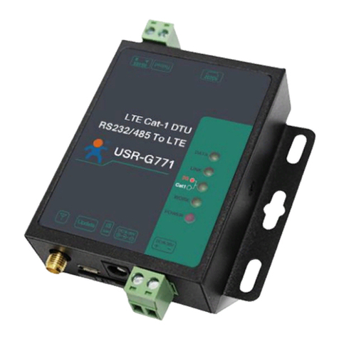
USR IOT USR-G771-E User manual
USR IOT
USR IOT USR-G771-E User manual

USR IOT
USR IOT USR-G786-G User manual


