UTS iSandBOX Standard User manual

1
Tel. +7-3822-901439
E-mail: world@ar-sandbox.com
www.ar-sandbox.com
Installation Manual
for iSandBOX hardware and software
system
Tomsk, Russia
2019

2
Safety Rules
To avoid incidents, it is PROHIBITED to:
● perform any maintenance operations while the plug is in the socket;
● use DYI or non-standard parts;
● cover ventilation slots;
● operate the device under high humidity conditions;
● operate the device under heavy dust concentration;
● replace the projector lamp while the device is connected to electric network;
● if the equipment was kept at temperatures below +10℃, wait at least two hours for it
to get to room temperature;
● dust the parts with a wet cloth;
● touch the parts with wet or damp hands;
● throw the parts;
● use ungrounded sockets.
The socket outlet should be located at an easily available place to allow quick
removal of the plug if necessary.

3
Index
1. Preparation ............................................................................................................................................... 4
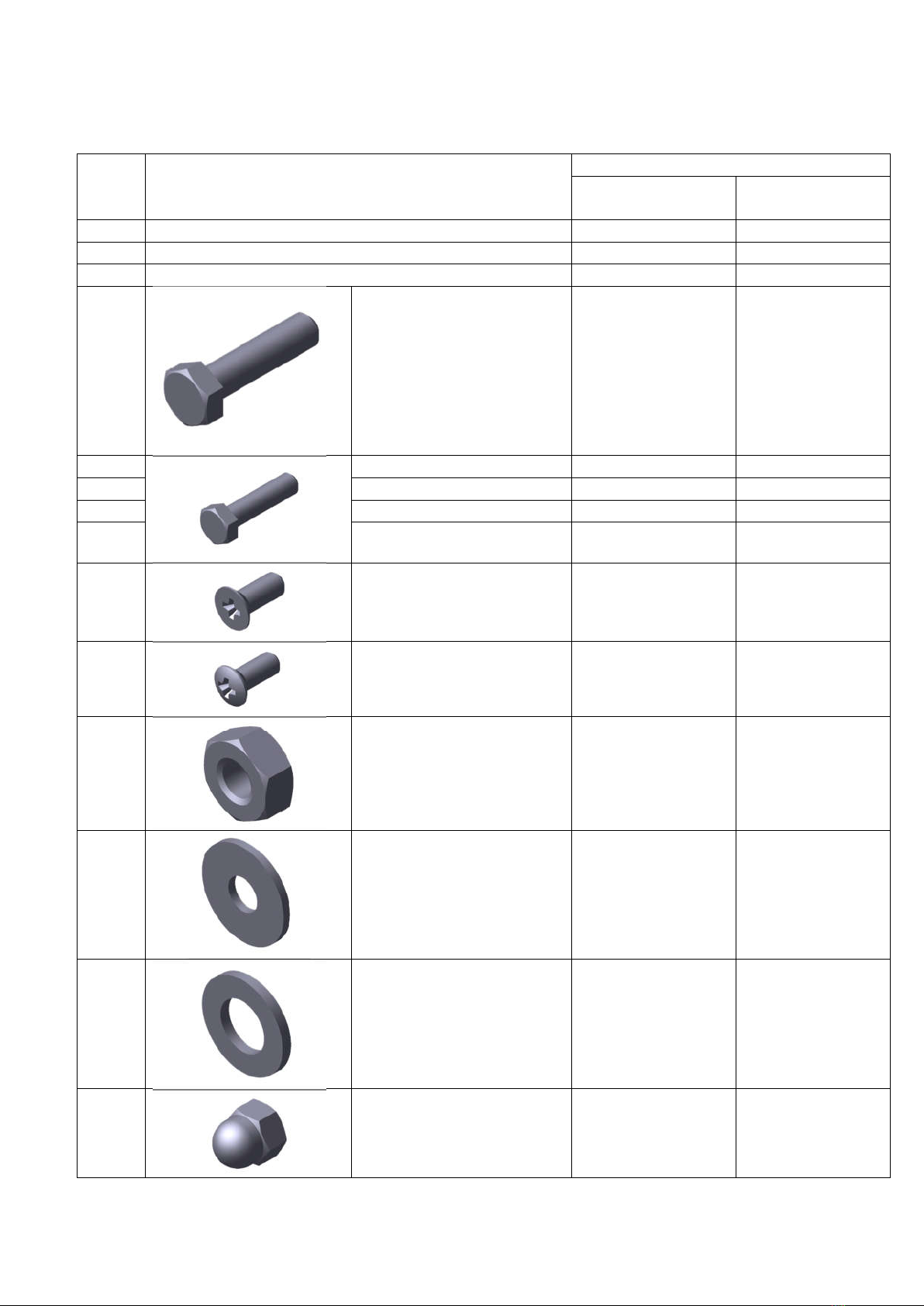
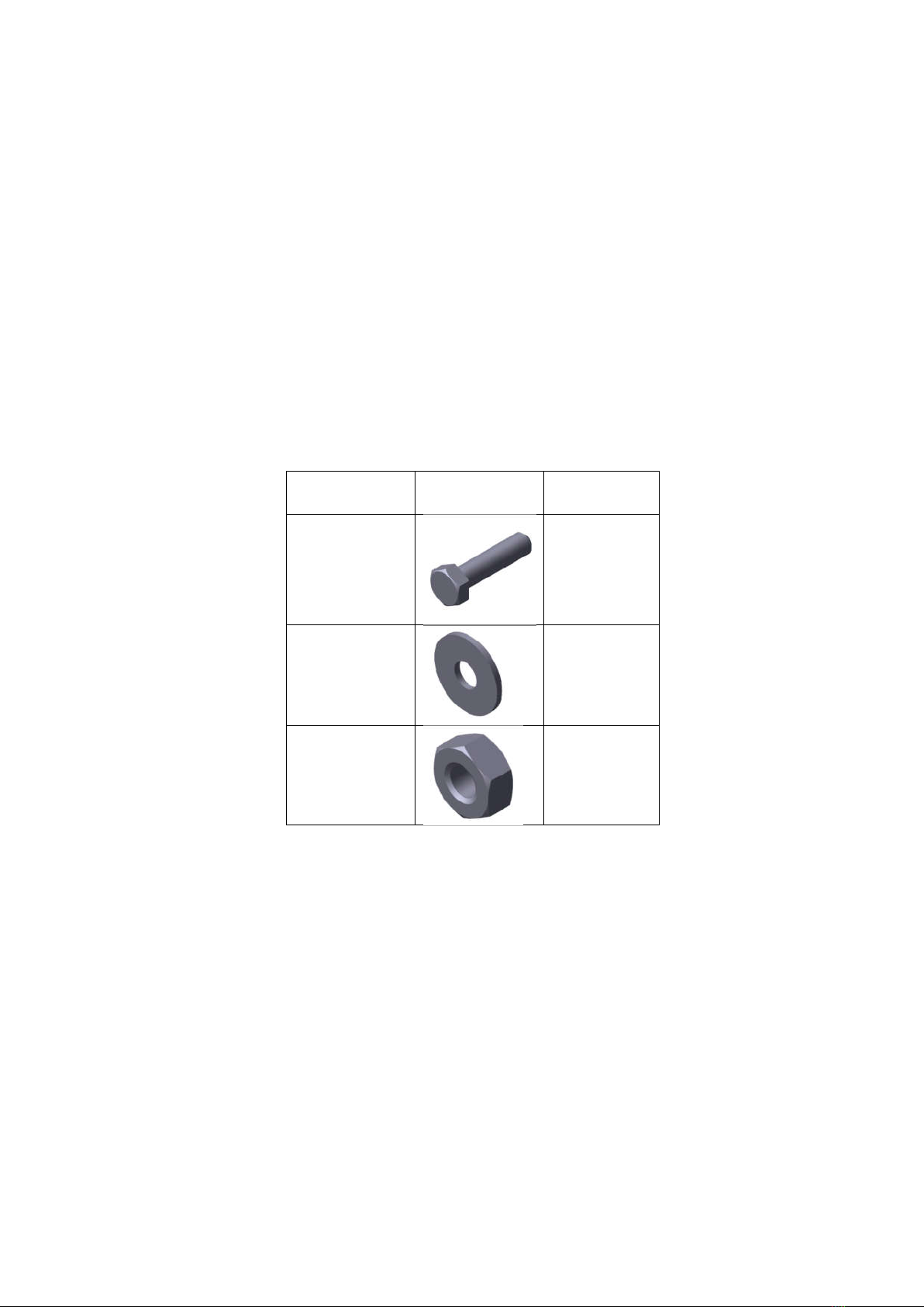
1.2. Set of tools and metalware for product assembly .................................................................................... 5
1.3 iSandBOX Standard / Mini Supply Package ............................................................................................ 6
2. Assembly .................................................................................................................................................. 9
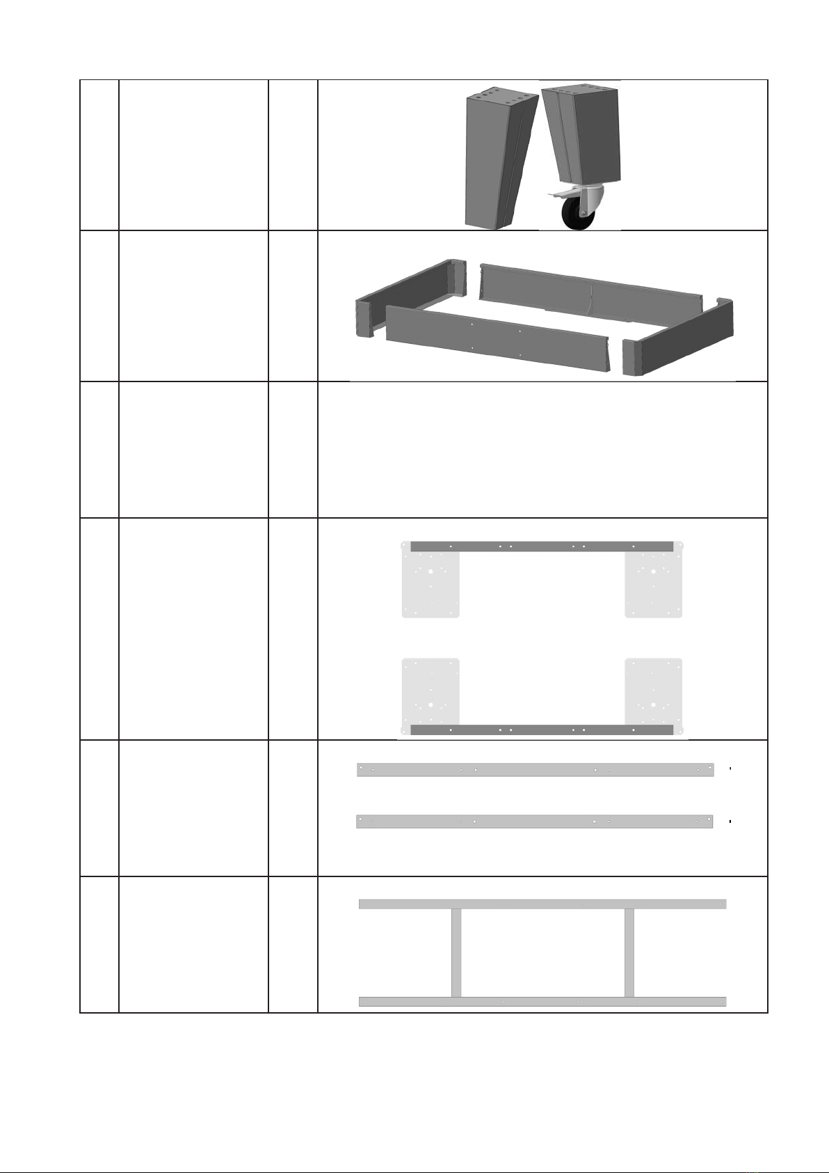
2.1. Frame assembly ....................................................................................................................................... 9
2.2. Installing the legs and column support ................................................................................................. 11
2.3. Installing the speakers ........................................................................................................................... 13
2.4. Assembling and installing the sand reservoir ........................................................................................ 15
2.5. Column installation ................................................................................................................................ 17
2.6. Installing the projector casing and connecting the cables .................................................................... 20
2.7. Placing the sand reservoir lining ........................................................................................................... 23

4
1. Preparation
Before starting the assembly and setting up your iSandBOX, check if the shipment package and
the provided set of tools and metalware are in place. Also check for defects (cracks, chips, sharp metal
edges).
Before assembling Standard and Mini versions, make sure you chose the right spot for your
interactive sandbox. If there are no wheels on the support legs, it is almost impossible to flip it over
(the weight of the system with the sand in it is about 400 kg).
Standard and Mini models are resistant to overturning only when the sandbox container is filled
with sand.
Assembly requires at least two people due to large and heavy parts.

5
1.2. Set of tools and metalware for product assembly
№ Description Quantity (ea.)
For iSandBOX
Standard
For iSandBOX
Mini
1. 10 wrench 2 2
2. 13 wrench 1 1
3. Philips screwdriver 1 1
4.
М8х20 screw 16 16
5.
М6х65 screw 4 4
6. М6х60 screw 16 14
7. М6х40 screw 16 16
8. М6х16 screw 22 22
9.
Flat screw М4х10 4 4
10.
Cup head screw М4х10 46 46
11.
М6 nut 44 42
12.
6 fender washer 102 98
13.
8 washer 16 16
14.
Plastic cap 22 20

6
1.3 iSandBOX Standard / Mini Supply Package
№ Description Num
ber
Image
1. Projector casing 1
2. Laminated
chipboard panel
(central, with B2
mark)
1
3. Laminated
chipboard panel
(side, with B1 and
B3 mark)
2
4. Column support 1
5. Sandbox column
with a casing for
PC base unit
1

7
6. Sand container
support legs with or
without wheels
4
7. Side walls of the
sand container
4
8. Sand container
lining
1
9. Spreader bar 2
10. Crossbar 2
11. Underframe 1

8
12. Lower column
housing
1
13. Acoustic system 1
14. Power cable 1
15. Box with tools and
metalware
1

9
2. Assembly
2.1. Frame assembly
Metalware Image Quantity
(ea.)
М6х40 screw
16
М6 washer
32
М6 nut
16
Table A. Metalware used for frame assembly
To assemble the frame, you will need: Spreader bar (А) – 2 ea.; crossbar – 2 ea. and underframe.
Fixing points are indicated in arrows of the same color in pairs.

10
Figure 1.
Secure the crossbeams to the spreader bar using М6х40 screws (8 ea.), М6 washers (16 ea.), M6
nuts (8 ea.) and a 10 wrench (Figure 2).
!Attention! Screw hats must be pointing down.
Figure 2.
Crossbeams must be installed correctly. The holes must be positioned on the corners of the
structure and should not be covered by the plates.
Secure the underframe using М6х40 screws (8 ea.), М6 washers and М6 nuts and a 10 wrench
(Figure 3).

11
!Attention! Screw hats must be pointing down.
Figure 3.
2.2. Installing the legs and column support
Metalware Image Quantity
(ea.)
М8х20 screw
16
М6х65 screw
4
М8 washer
16

12
М6 washer
8
М6 nut
4
Table B. Metalware used for installing legs and support column
Secure the legs on the plates using М8х20 screws (16 ea.), М8 washers (16 ea.) and a 13 wrench.
Fixing points are shown on Figure 4.
The correct position of the legs is shown with the arrows of the same color (stickers are located on
the leg and the plate).
Figure 4.
If the legs have wheels, it is necessary to secure them to the plates using М8х20 screws (16 ea.),
М8 washers (16 ea.) and a 13 wrench. Fixing points are shown on Figure 5.
The correct position of the legs is shown with the arrows of the same color (stickers are located on
the leg and the plate).

13
Figure 5.
Secure the column support using М6х65 screws (4 ea.), М6 washers (8 ea.), M6 nuts and a 10
wrench. Fixing points are shown on Figure 6.
The support should be located on the side of frame A. The fixing is shown on Figure 6 (B).
Figure 6.
2.3. Installing the speakers

14
Metalware Image Quantity
(ea.)
Flat screw
М4х10
4
Table C. Metalware used for speakers installation
Speakers are supplied with mounting brackets (Figure 7). The upper bracket is furnished with
threaded fixtures. There is no need to disassemble them.
Figure 7.
Place the speaker (with a threaded fixture) onto the frame. The plastic parts of the frame have
threaded fixtures.
Tighten the speaker using М4х10 flat screw (2 ea.) and a 7 wrench (figure 8). Repeat this step for
the second speaker (with a threaded fixture) on the other plate.
Figure 8.
Connect speaker cables to the jacks of the subwoofer located on the inner side of the column
support.

15
2.4. Assembling and installing the sand reservoir
Metalware Image Number for
iSandBOX Standard
(ea.)
Number for iSandBOX
Mini (ea.)
М6х16 screw
8 8
М6х60 screw
16 14
М6 washer
48 44
М6 nut
24 22
Plastic cap
16 14
Table D. Metalware used for the sand reservoir installation
Place the laminated chipboard panels on the assembled frame, following the numbers shown in
Figure 9.
Figure 9.

16
Assemble the sand reservoir using М6х16 screws (8 ea.), М6 washers (16 ea.), М6 nuts, and a 10
wrench.
Figure 10.
Mount and secure the sand reservoir on the laminated chipboard panels (Figure 11).
Figure 11.
Install the sand reservoir for the iSandBOX Standard using М6х60 screws (16 ea.), М6 washers
(32 ea.) and М6 nuts using a 10 wrench. After that, cover thread ends with plastic caps (16 ea.) (Figure
12).
Figure 12.

17
Install the sand reservoir for the iSandBOX Mini version using М6х60 (14 ea.), М6 washers (28
ea.) and nuts (14 ea.) using a 10 wrench. Then close thread ends with plastiс caps (14 ea.) (Figure 13).
Figure 13.
2.5. Column installation
Metalware Image Quantity (ea.)
М6х16 screw
8
М6 washer
8
М4х10 cup
head screw
4
Table E. Metalware used for installing the column

18
Place the column on the frame, inserting the mounting hooks into the bearer holes (Figure 14).
Figure 14.
Connect the column to the support and the container using М6х16 screws (8 ea.), М6 washers (8
ea.) and a 10 wrench (Figure 15).
Figure 15.

19
Put the sound wire and power cable of the audio system subwoofer through the hole at the column
base inside the column. Connect these wires to the slots on the motherboard of the base unit and to the
power filter (Figure 16).
Figure 16.
Place the casing on the base of the column and secure it with a М4х10 cup head screw (4 ea.)
(Figure 17). Then, connect the sandbox power cable to the power jack on the right side wall of the
column (Figure 17).
Figure 17.

20
2.6. Installing the projector casing and connecting the cables
Metalware Image Quantity (ea.)
М6х16 screw
6
М6 washer
6
Plastic cap
6
Table F. Metalware used for projector casing installation
Install the projector casing to the fixture plate. Put the cable set inside the casing and secure it
with М6х16 screws (6 ea.), М6 washers (6 ea.) and a 10 wrench (Figure 18).
Then cover thread ends with plastic caps (6 ea.).
Figure 18.
This manual suits for next models
1
Table of contents
Popular Educational Equipment manuals by other brands

Rompa
Rompa 18372 manual

Opitec
Opitec Thermo fan 105.434 manual

Simulaids
Simulaids RANDY 9000 Instruction and Care Manual

Seiko
Seiko ER1100 Operation manual

Next Level Racing
Next Level Racing FLIGHT SIMULATOR BOEING MILITARY EDITION instruction manual

John Lewis
John Lewis Illuminated globe quick start guide