Version 16.07.2013 VL2-DVD900
Contents
1. Prior to installation
1.1. Delivery contents
1.2. Checking the compatibility of vehicle and accessories
1.3. Dip-switch settings
1.3.1. Vehicle selection (dip 7-8)
1.3.1.1. Video signal selection after-market navigation (Dip 4)
1.3.2. Enabling the interface’s video inputs (dip 1-3)
1.3.3. Rear-view camera settings (dip 5)
2. Installation
2.1. Place of installation
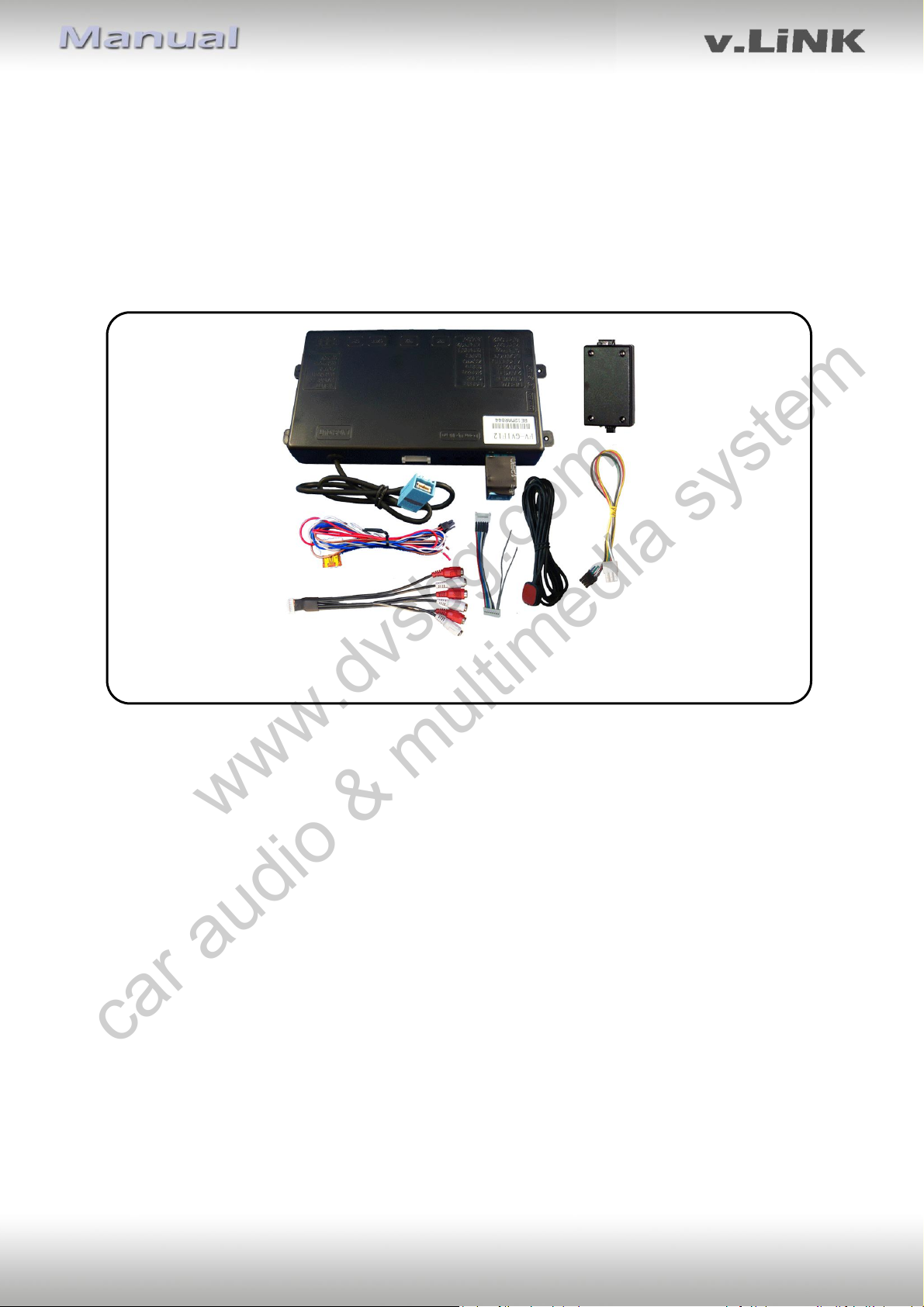
2.2. Connection schema
2.3. Connecting video-interface and 6pin cable
2.4. Connection to the factory monitor
2.5. Connecting peripheral devices
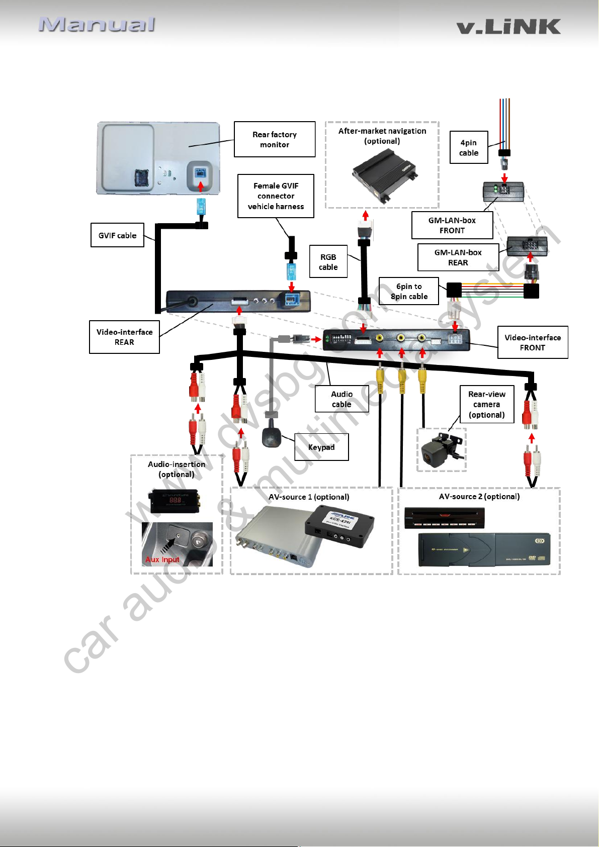
2.5.1. Video-sources to IN1 and IN2
2.5.2. Audio-switch and audio-insertion
2.5.3. After-market rear-view camera
2.5.4. After-market navigation
2.6. Connecting video-interface and keypad
2.7. Picture settings
2.8. Activation of parking guide lines for rear-view camera
3. Interface operation
4. Specifications
5. Connections (video-interface)
6. Technical support
Legal Information
By law, watching moving pictures while driving is prohibited, the driver must not be
distracted. We do not accept any liability for material damage or personal injury resulting,
directly or indirectly, from installation or operation of this product. This product should only
be used while standing or to display fixed menus or rear-view-camera video when the
vehicle is moving, for example the MP3 menu for DVD upgrades.
Changes/updates of the vehicle’s software can cause malfunctions of the interface. We
offer free software-updates for our interfaces for one year after purchase. To receive a free
update, the interface must be sent in at own cost. Labor cost for and other expenses
involved with the software-updates will not be refunded.
www.dvsbg.com
car audio & multimedia system