Version 23.02.2018 HW:25 (V92) CI-VL2-CONCERT
1.3.2.3. RGB-video input signal selection for after-market navigation (Dip 4)
If after-market RGB navigation or other RGB video source is connected, the source’s RGB
output signal must match the interface’s RGB video input setting.
1.3.2.4. Rear-view camera setting (dip 5)
In the OFF position, the interface switches to factory LVDS picture while the reverse gear is
engaged to display factory rear-view camera or factory optical park system picture.
If the switch is set to ON, the interface switches to its rear-view camera input while the
reverse gear is engaged.
1.3.2.5. Monitor adjustments (dip 7-8)
Set Dip 7 and 8 to OFF.
2. Installation
To install the interface, first switch off the ignition and disconnect the vehicle’s battery.
Please read the owner`s manual of the car, regarding the battery`s disconnection! If
required, enable the car`s Sleep-mode (hibernation mode)
In case the sleep-mode does not succeed, the disconnection of the battery can be done
with a resistor lead.
If the necessary stabilized power supply for the interface is not taken directly from the
battery, the chosen connection has to be checked for being constantly stabile.
The interface needs a permanent 12V source!
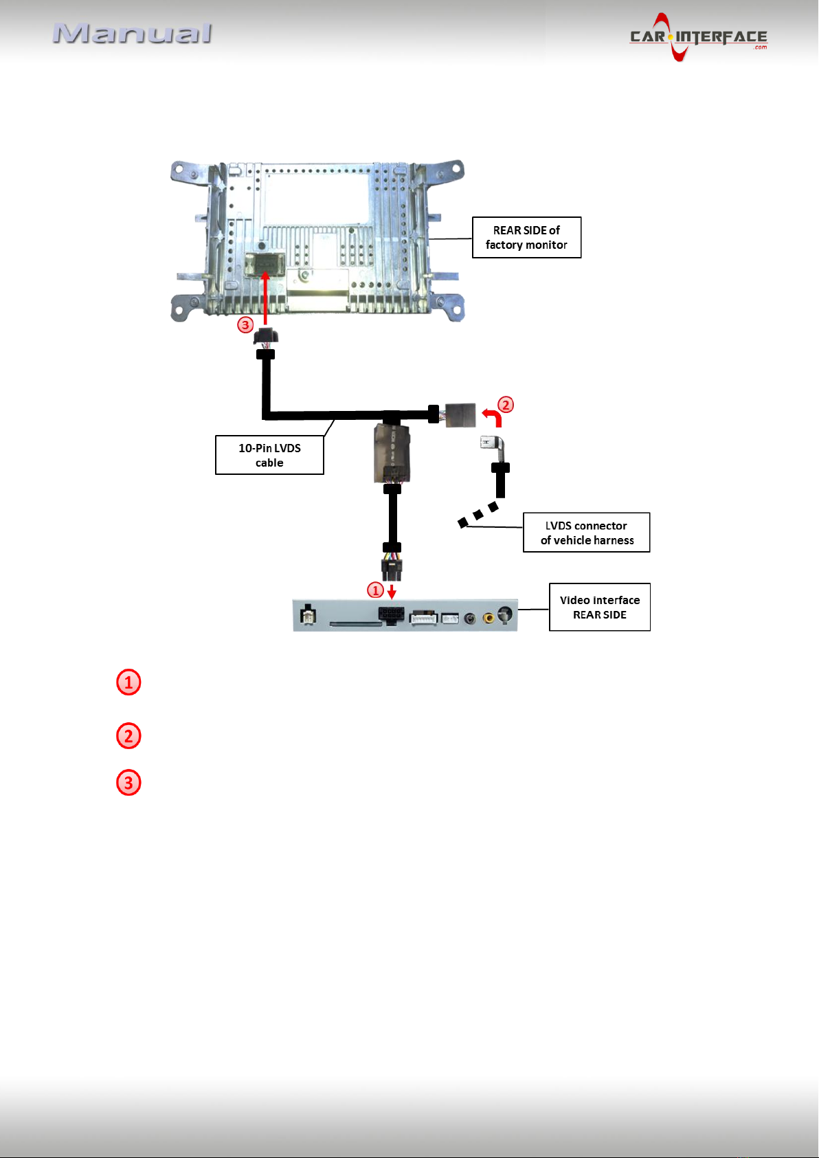
2.1. Place of installation
The interface is built to be installed on the backside of the factory monitor, at the climate
control panel and on the backside of the vehicle’s head unit.