V-ZUG DEHMR 5 User manual

Dunstabzug
Range hood
Davlumbaz
DEHMR 5/7/8
Betriebsanleitung
Operating instructions
Kullanma kılavuzu
V-ZUG Ltd

2
2
INHALTSVERZEICHNIS
EMPFEHLUNGEN UND HINWEISE .......................................................................................... ............... ............... ........... 3
CHARAKTERISTIKEN................................................................................................................ ............... ............... ............ 4
MONTAGE ................................................................................................................... ............... ............... ............... ........... 5
BEDIENUNG................................................................................................................ ............... ............... ............... ........... 7
WARTUNG................................................................................................................................. ............................ ............... 8
INDEX
RECOMMENDATIONS AND SUGGESTIONS .................................................................................................................. 10
CHARACTERISTICS .......................................................................................................................................................... 11
INSTALLATION.................................................................................................................................................................... 12
USE...................................................................................................................................................................................... 14
MAINTENANCE....................................................................................................................................................................15
IÇERIKLER
TAVSIYELER VE ÖNERILER.............................................................................................................................................. 17
ÖZELLIKLER........................................................................................................................................................................ 18
MONTAJ............................................................................................................................................................................... 19
KULLANIM ........................................................................................................................................................................... 21
BAKIM .................................................................................................................................................................................. 22
DE
EN
TR

DE 3
3
EMPFEHLUNGEN UND HINWEISE
Diese Gebrauchsanleitung gilt für mehrere Geräte-Ausführungen. Es ist möglich, dass einzelne Ausstat-
tungsmerkmale beschrieben sind, die nicht auf Ihr Gerät zutreffen.
MONTAGE
• Der Hersteller haftet nicht für Schäden, die auf eine fehlerhafte oder unsachgemäße Montage zurückzuführen
sind.
• Der minimale Sicherheitsabstand zwischen Kochmulde und Haube muss 650 mm betragen (einige Modelle
können an einer geringeren Höhe installiert werden, beziehen Sie sich dazu auf den Absatz Raumbedarf und
Installation).
• Prüfen, ob die Netzspannung mit dem Wert auf dem im Haubeninneren angebrachten Schild übereinstimmt.
• Bei Geräten der Klasse I ist sicherzustellen, dass die elektrische Anlage des Wohnhauses über eine vor-
schriftsmäßige Erdung verfügt.
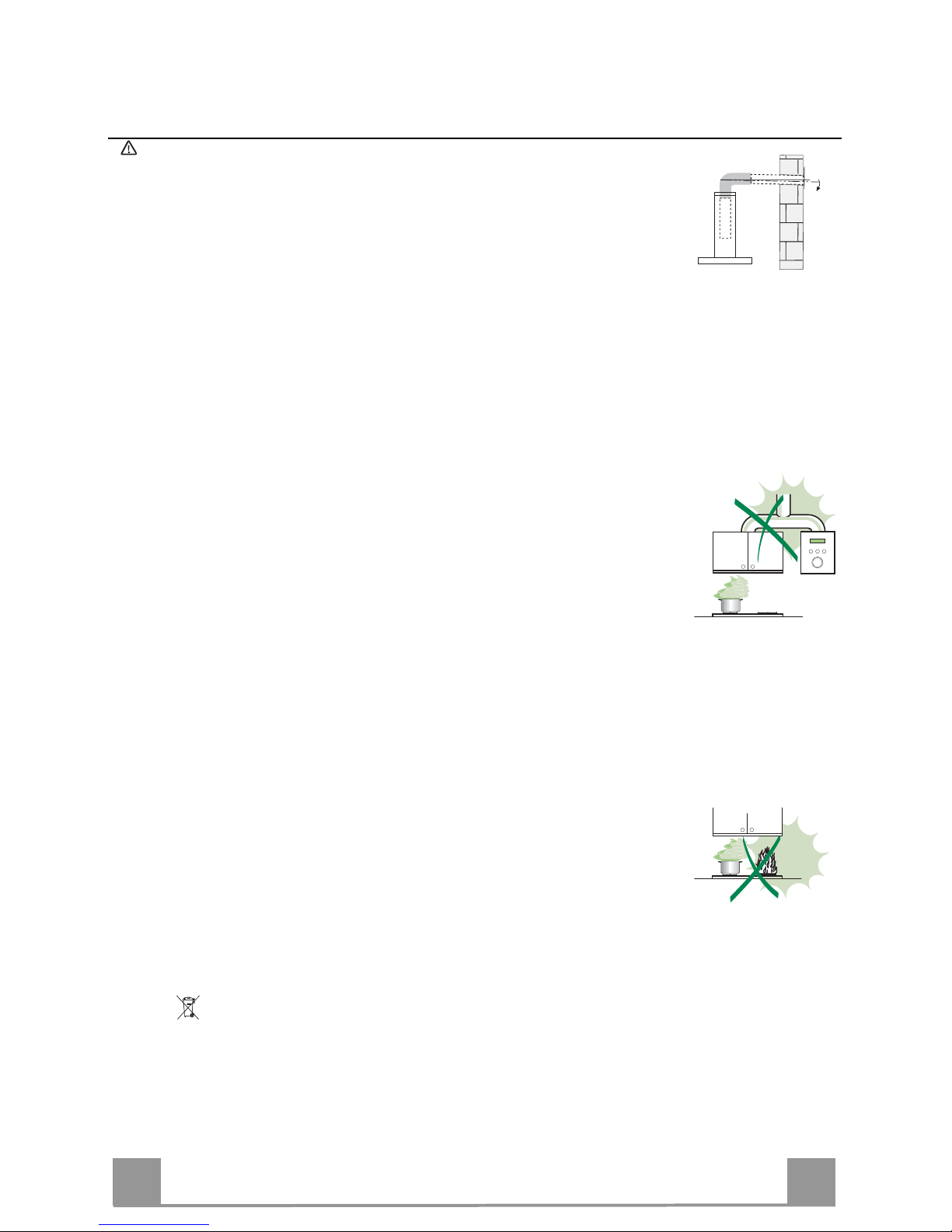
• Das Anschlussrohr der Haube zur Luftaustrittsöffnung muss einen Durchmesser von 120 mm oder darüber
aufweisen. Der Rohrverlauf muss so kurz wie möglich sein.
• Die Haube darf an keine Entlüftungsschächte angeschlossen werden, in die Verbrennungsgase (Heizkessel,
Kamine usw.) geleitet werden.
• Werden im Raum außer der Dunstabzugshaube andere, nicht elektrisch betriebene (z.B. gasbetriebene) Gerä-
te verwendet, muss für eine ausreichende Belüftung gesorgt werden. Sollte die Küche diesbezüglich nicht
entsprechen, ist an einer Aussenwand eine Öffnung anzubringen, die Frischluftzufuhr gewährleistet. Der Ge-
brauch ist dann sachgemäß und sicher, wenn der max. Unterdruck des Raums nicht mehr als 0,04 mbar be-
trägt.
• Ein schadhaftes Kabel muss vom Hersteller oder vom technischen Kundendienst ausgewechselt werden,
damit jedes Risiko vermieden wird.
• Wenn die Anweisungen für die Installation für die Gaskochgeräts einen größeren Abstand oben angegeben,
muss dies berücksichtigt werden. Vorschriften über die Entlastung der Luft müssen erfüllt sein.
BEDIENUNG
• Die Dunstabzugshaube ist ausschließlich zum Einsatz im privaten Haushalt und zur Beseitigung von Kü-
chengerüchen vorgesehen.
• Unsachgemäßer Einsatz der Haube ist zu unterlassen.
• Große Flammen bei eingeschalteter Haube niemals unbedeckt lassen.
• Die Intensivität der Flamme ist so zu regulieren, dass sie den Topfboden nicht überragt.
• Frittiergeräte müssen während des Gebrauchs stets beaufsichtigt werden: überhitztes Öl kann sich entzünden.
• Keine flambierten Speisen unter der Abzugshaube zubereiten: Brandgefahr.
• Dieses Gerät darf nicht von Kindern oder Personen mit verminderten psychischen, sensorischen und geisti-
gern Fähigkeiten, oder von Personen ohne Erfahrung und Kenntnisse benutzt werden, sofern sie nicht von für
ihre Sicherheit verantwortlichen Personen beaufsichtigt und beim Gebrauch des Geräts angeleitet werden.
• Kinder dürfen sich nicht unbeaufsichtigt in der Nähe des Geräts aufhalten und auf keinen Fall mit dem Gerät
spielen.
• “ACHTUNG: Die zugänglichen Teile können sehr heiß werden, wenn sie mit Kochgeräten eingesetzt
werden.”.
WARTUNG
• Bevor Wartungsarbeiten durchgeführt werden, muss die Stromzufuhr zur Haube unterbrochen werden,
indem der Stecker gezogen oder der Hauptschalter abgeschaltet wird.
• Bei der Filterwartung müssen die vom Hersteller empfohlenen Zeiträume zum Austauschen der Filter ge-
nauestens eingehalten werden (Brandgefahr).
• Zur Reinigung der Haubenflächen empfehlen wir ein feuchtes Tuch und ein mildes Flüssigreinigungsmittel.
Das Symbol auf dem Produkt oder seiner Verpackung weist darauf hin, dass dieses Produkt nicht als normaler Haushaltsabfall
zu behandeln ist, sondern an einem Sammelpunkt für das Recycling von elektrischen und elektronischen Geräten abgegeben werden
muss. Durch Ihren Beitrag zum korrekten Entsorgen dieses Produkts schützen Sie die Umwelt und die Gesundheit Ihrer Mitmenschen.
Umwelt und Gesundheit werden durch falsches Entsorgen gefährdet. Weitere Informationen über das Recycling dieses Produkts
erhalten Sie von Ihrem Rathaus, Ihrer Müllabfuhr oder dem Geschäft, in dem Sie das Produkt gekauft haben.
2°

DE 4
4
CHARAKTERISTIKEN
Platzbedarf
Komponenten
Bez. Menge Produktkomponenten
11 Haubenkörper komplett mit: Bedienelemente, Beleuch-
tung, Filter, Absaugeinheit
81 Luftstromrichtungsgitter
91 Reduzierflansch ø 150-120 mm
10 1 Flansch mit Rückstauklappe ø 150 mm
Bez. Menge Produktkomponenten
12a 10 Schrauben (8 für 52cm Dunstabzugshaube)
12e 2 Schrauben 2,9 x 9,5
Menge Unterlagen
1 Betriebsanleitung
10
9
812e

DE 5
5
MONTAGE
Montage des Haubenkörpers
BEVOR DIE HAUBE AM HÄNGESCHRANK MONTIERT WIRD, WIE FOLGT VORGEHEN:
• Das Absaugpaneel herausziehen.
• Das Paneel vom Haubenkörper lösen, in dem der spezielle
Hebel des Befestigungszapfens verschoben wird.
• Die Fettfilter entfernen.
• Die elektrische Steckverbindung der Bedienelemente abhängen,
indem die Verbinder gelöst werden.
• Die Drähte der Beleuchtung abhängen, indem die
Verbinder gelöst werden.
• Den Rahmen durch
Aufschrauben der 6
Schrauben ausbauen.
• Die Haube kann direkt an der Unterseite des
Hängeschranks angebracht werden min. (650
mm von der Kochfläche).
• An der Unterseite des Hängeschranks eine
Aussparung anfertigen, wie abgebildet.
• Die Haube einsetzen und die seitlichen
Halterungen einhaken.
• Mit den 10 mitgelieferten Schrauben 12a
befestigen.
• Durch Festschrauben von unten der Schrauben
Vf definitiv blockieren.
• Den Rahmen mit den 6 zuvor entfernten Schrauben wieder befestigen, die elektrische
Verbindung der Bedienelemente und der Beleuchtung wieder anschließen, den Fettfilter und
das Paneel wieder einbauen.
0
260
13
495 - 675

DE 6
6
Anschlüsse
ANSCHLUSS IN ABLUFTVERSION
Bei Abluftbetrieb kann die Haube vom Installateur
wahlweise mittels Rohr oder Schlauch (ø150 oder
120mm) an die Außenrohrleitung angeschlossen wer-
den.
• Den Flansch mit Rückstauklappe 10 anbringen.
• Das Rohr mit geeigneten Rohrschellen fixieren. Das
hierzu erforderliche Material wird nicht mitgeliefert.
• Bei Verwendung eines Anschlussrohres ø 120 den
Reduzierflansch 9 am Flansch mit Rückstauklappe
10 anbringen.
• Eventuell vorhandene Aktivkohlefilter entnehmen.
.
ø 120
ø 150
10
10
9
ANSCHLUSS IN UMLUFTVERSION
• In das eventuell über der Haube vorhandene Bord ein
Loch ø 125 mm bohren.
• Den Reduzierflansch 9am Haubenaustritt anbringen.
• Den Flansch beim Luftaustritt am Bord oberhalb der
Haube mittels Rohr oder Schlauch ø120 mm an-
schließen.
• Das Rohr mit geeigneten Rohrschellen fixieren. Das
hierzu erforderliche Material wird nicht mitgeliefert.
• Das Luftleitgitter 8mit Hilfe von 2 der mitgelieferten
Schrauben 12e (2,9 x 9,5) beim Austritt der rückzu-
führenden Luft fixieren.
• Sicherstellen, dass der Aktivkohle-Geruchsfilter vor-
handen ist.
9
ø 125
8
12e
ELEKTROANSCHLUSS
• Bei Anschluss der Haube an das Stromnetz muss ein zweipoliger Schalter mit einem Öff-
nungsweg von mindestens 3 mm zwischengeschaltet werden.

DE 7
7
BEDIENUNG
A B C D E F G H
Schalttafel
Taste Funktion Display
ASchaltet den Absaugmotor bei der ersten Geschwindig-
keitsstufe ein und bei allen Betriebsgeschwindigkeiten
aus.
Zeigt die eingestellte Geschwindigkeit an
BVermindert die Betriebsgeschwindigkeit. Zeigt die eingestellte Geschwindigkeit an
CErhöht die Betriebsgeschwindigkeit. Zeigt die eingestellte Geschw
i
ndigkeit an
DAktiviert von jeder Geschwindigkeit aus, auch bei abge-
stelltem Motor, die Intensivgeschwindigkeit, die auf 10
Minuten zeitgeregelt ist. Nach Ablauf dieser Zeit kehrt
das System zu der zuvor eingestellten Geschwindigkeit
zurück. Für die Beseitigung von sehr intensiven Koch-
dünsten geeignet.
Macht einmal pro Sekunde abwechselnd HI und die Rest-
zeit sichtbar.
Mit zirka 5 Sekunden langem Gedrückthalten der Taste
bei abgeschalteten Verbrauchern (Motor+Licht) wird der
Alarm der Aktivkohlefilter aktiviert / deaktiviert.
FC+Pünktchen (2 Mal Blinken)–Alarm aktiviert.
FC+Pünktchen (1 Mal Blinken)–Alarm deaktiviert.
E24H Funktion:
Aktiviert den Motor bei der ersten Geschwindigkeitsstufe
und ermöglicht eine Absaugung von 1 Minuten pro Stun-
de.
Zeigt 24 an und der Punkt unten rechts blinkt einmal pro
Sekunde, während der Motor in Betrieb ist
Wird durch Drücken der Taste deaktiviert.
Bei laufendem Filteralarm wird durch 3 Sekunden anhal-
tendes Drücken der Taste ein Reset des Alarms ausgelöst.
Derlei Anzeigen sind nur bei abgestelltem Motor sichtbar.
FF blinkt drei Mal.
Nach abgeschlossener Prozedur verlöscht die bisherige
Anzeige:
FG zeigt an, dass der Metallfettfilter gewaschen werden
muss. Dieser Alarm wird nach 100 effektiven Betriebs-
stunden der Abzugshaube ausgelöst.
FC zeigt an, dass die Aktivkohlefilter ausgewechselt
und die Metallfettfilter gewaschen werden müssen. Dieser
Alarm wird nach 200 effektiven Betriebsstunden der Ab-
zugshaube ausgelöst.
FFunktion Delay
Aktiviert das automatische Ausschalten mit einer Verzö-
gerung von 30’. Vervollständigt die Beseitigung von
Restgerüchen. Kann von jeder Position aus eingeschaltet
werden und wird durch Drücken der Taste oder Abstellen
des Motors ausgeschaltet.
Zeigt die Betriebsgeschwindigkeit an und der Punkt unten
rechts blinkt einmal pro Sekunde.
Mit zirka 5 Sekunden langem Gedrückthalten der Taste
bei abgeschalteten Verbrauchern (Motor+Licht) wird die
Fernbedienung aktiviert / deaktiviert.
IR+Pünktchen (2 Mal Blinken)–Alarm aktiviert.
IR+Pünktchen (1 Mal Blinken)–Alarm deaktiviert.
GSchaltet die Beleuchtungsanlage auf höchster Intensitäts-
stufe ein und aus.
HSchaltet die Beleuchtung im Modus der Notbeleuchtung
ein oder aus.

DE 8
8
WARTUNG FERNBEDIENUNG (OPTI
O
N)
Dieses Gerät kann mit einer Fernbedienung gesteuert werden, welche mit
alkalischen Zink-Kohle-Batterien 1,5 V des Standardtyps LR03-AAA
versorgt wird (nicht mitgeliefert).
• Die Fernbedienung nicht in die Nähe von Hitzequellen legen.
• Batterien müssen vorschriftsmäßig entsorgt werden.
Öffnen des Paneels
• Das Paneel herausziehen.
• Die Außenflächen mit einem feuchten Lappen und einem neutralen
Flüssigreiniger säubern.
• Auch Innen mit einem feuchten Lappen und einem neutralen
Reinigungsmittel säubern; keine nassen Tücher oder Schwämme, oder
gar Wasser verwenden, und keine schleifenden Mittel einsetzen.
Metallfettfilter
Die Fettfilter sind spülmaschinengeeignet und müssen gewaschen
werden, sobald am Display die Aufschrift FG erscheint oder mindestens
alle 2 Monate, oder auch öfter, je nach Intensität des Gebrauchs.
Reset des Alarmsignals
• Die Beleuchtung und den Absaugmotor abschalten und dann die 24-
Stunden-Funktion deaktivieren, falls diese zuvor aktiv war.
• Die Taste Edrücken (siehe Absatz BEDIENUNG).
Reinigung der Filter
• Das Komfort-Paneel öffnen, indem es zur entsprechenden Kerbe
gezogen wird
• Die Filter einzeln ausbauen, indem sie in den hinteren Teil der Gruppe
geschoben und gleichzeitig nach unten gezogen werden.
• Die Filter waschen, ohne sie zu verbiegen, und vor dem erneuten
Einbau trocknen lassen. (Die Farbe der Filteroberfläche kann sich mit
der Zeit verändern, was aber die Wirksamkeit keinesfalls
beeinträchtigt.)
• Nun die Filter wieder einbauen, so dass der Griff nach der äußeren
Sichtseite zeigt.
• Die Komfort-Paneele wieder verschließen.

DE 9
9
Aktivkohle-Geruchsfilter (Filterversion)
Die Aktivkohle-Geruchsfilter sind spülmaschinengeeignet und müssen gewaschen werden,
sobald am Display die Led S1 blinkt, oder mindestens alle 4 Monate, oder auch öfter, je nach
Intensität des Gebrauchs. Nach max. 5 Wäschen müssen die Filter erneuert werden. Die
Alarmmeldung, wenn zuvor aktiviert, erfolgt nur, wenn der Absaugmotor zugeschaltet ist.
Aktivierung des Alarmsignals
• Bei den Filterversionen der Abzugshauben wird die Alarmanzeige für Filtersättigung im
Augenblick der Installation oder in der Folge aktiviert.
• Die Beleuchtung und den Absaugmotor abstellen.
• Die Taste D zirka 5 Sekunden lang drücken.
• 2 Mal Blinken der Aufschrift FC+Pünktchen -- Alarm für Aktivkohlefiltersättigung
AKTIVIERT
• 1 Mal Blinken der Aufschrift FC+Pünktchen -- Alarm für Aktivkohlefiltersättigung
DEAKTIVIERT
AUSWECHSELN DES AKTIVKOHLE-GERUCHSFILTERS
Reset des Alarmsignals
• Die Beleuchtung und den Absaugmotor abschalten und dann die 24-
Stunden-Funktion deaktivieren, falls diese zuvor aktiv war.
• Die Taste E drücken (siehe Absatz BEDIENUNG).
Auswechseln des Filters
• Das Komfort-Paneel öffnen, indem es zur entsprechenden Kerbe gezo-
gen wird
• Die Fettfilter aus Metall entfernen.
• Die verbrauchten Aktivkohle-Geruchsfilter wie angegeben ausbauen
(A).
• Die ausgewaschenen Filter wie angegeben wieder einbauen (B).
• Die Fettfilter aus Metall wieder einbauen.
• Die Komfort-Paneele wieder verschließen.
A
B
Beleuchtung
LED-Strahler
• Für den Austausch der LED-Strahler wenden Sie sich bitte an den
Kundendienst.
Achtung: Dieses Gerät ist mit einer weißen LED-Lampe der Klasse 1M
gemäß EN 60825-1 ausgestattet: 1994 + A1:2002 + A2:2001; max.
gelieferte Lichtleistung @439nm: 7µW. Nicht direkt mit optischen
Instrumenten (Fernglas, Lupe, usw.) in das Licht schauen.

EN 1
10
RECOMMENDATIONS AND SUGGESTIONS
The Instructions for Use apply to several versions of this appliance. Accordingly, you may find de-
scriptions of individual features that do not apply to your specific appliance.
INSTALLATION
• The manufacturer will not be held liable for any damages resulting from incorrect or improper instal-
lation.
• The minimum safety distance between the cooker top and the extractor hood is 650 mm (some
models can be installed at a lower height, please refer to the paragraphs on working dimensions and
installation).
• Check that the mains voltage corresponds to that indicated on the rating plate fixed to the inside of
the hood.
• For Class I appliances, check that the domestic power supply guarantees adequate earthing.
Connect the extractor to the exhaust flue through a pipe of minimum diameter 120 mm. The route of
the flue must be as short as possible.
• Do not connect the extractor hood to exhaust ducts carrying combustion fumes (boilers, fireplaces,
etc.).
• If the extractor is used in conjunction with non-electrical appliances (e.g. gas burning appliances), a
sufficient degree of aeration must be guaranteed in the room in order to prevent the backflow of ex-
haust gas. The kitchen must have an opening communicating directly with the open air in order to
guarantee the entry of clean air. When the cooker hood is used in conjunction with appliances sup-
plied with energy other than electric, the negative pressure in the room must not exceed 0,04 mbar to
prevent fumes being drawn back into the room by the cooker hood.
• In the event of damage to the power cable, it must be replaced by the manufacturer or by the tech-
nical service department, in order to prevent any risks.
• If the instructions for installation for the gas hob specify a greater distance specified above, this has to
be taken into account. Regulations concerning the discharge of air have to be fulfilled.
USE
• The extractor hood has been designed exclusively for domestic use to eliminate kitchen smells.
• Never use the hood for purposes other than for which it has been designed.
• Never leave high naked flames under the hood when it is in operation.
• Adjust the flame intensity to direct it onto the bottom of the pan only, making sure that it does not
engulf the sides.
• Deep fat fryers must be continuously monitored during use: overheated oil can burst into flames.
• Do not flambè under the range hood; risk of fire
• This appliance is not intended for use by children or persons with reduced physical, sensory or men-
tal capabilities, or lack of experience and knowledge, unless they have been given supervision or in-
struction concerning use of the appliance by a person responsible for their safety.
• Children should be supervised to ensure that they do not play with the appliance.
• “ CAUTION: Accessible parts may become hot when used with cooking appliances.”.
MAINTENANCE
• Switch off or unplug the appliance from the mains supply before carrying out any maintenance
work.
• Clean and/or replace the Filters after the specified time period (Fire hazard).
• Clean the hood using a damp cloth and a neutral liquid detergent.
The symbol on the product or on its packaging indicates that this product may not be treated as household waste. Instead it shall
be handed over to the applicable collection point for the recycling of electrical and electronic equipment. By ensuring this product is
disposed of correctly, you will help prevent potential negative consequences for the environment and human health, which could
otherwise be caused by inappropriate waste handling of this product. For more detailed information about recycling of this product,
please contact your local city office, your household waste disposal service or the shop where you purchased the product.
2°

EN 1
11
CHARACTERISTICS
Dimensions
Components
Ref. Q.ty Product Components
11 Hood Body, complete with :Controls, Light, Blower,
Filters
81 Directioned grid
9 1 Reducer Flange ø 150-120 mm
10 1 Damper ø 150 mm
Ref. Q.ty Installation Components
12a 10 Screws (8 for 52 cm Hood)
12e 2 Screws 2,9 x 9,5
Q.ty Documentation
1 Instruction Manual
10
9
812e

EN 1
12
INSTALLATION
Fitting the Hood canopy
BEFORE FITTING THE HOOD TO THE WALL UNIT, PROCEED AS FOLLOWS:
• Open the suction panel by turning the specific knob.
• Disconnect the panel from the hood canopy by sliding the
fixing pin lever.
• Remove grease filters.
• Disconnect the wires to the Commands at the connectors.
• Disconnect the wires to the Light at the connectors.
• Remove the frame by un-
fastening the 6 screws.
• The Hood can be installed directly on the
underside of the wall unit (Minimum 650 mm
from the Cooker Hob).
• Create an opening in the bottom of the wall
unit, as shown.
• Insert the hood until the side supports snap
into place.
• Fasten using the 10 screws 12a provided.
• Lock in position by tightening the screws Vf
from underneath the hood.
• Screw the Frame back into place using the 6 screws removed as described above, re-connect
the wires to the Commands and Light, replace the metal grease filter and the Panel.
0
260
13
495 - 675

EN 1
13
Connections
DUCTED VERSION AIR EXHAUST SYSTEM
When installing the ducted version, connect the hood to
the chimney using either a flexible or rigid pipe ø 150
or 120mm, the choice of which is left to the installer.
• Install the dumper 10
• Fix the pipe in position using adequate pipe clamps
(not supplied).
• To install a ø 120 mm air exhaust connection, insert
the reducer flange 9on the dumper 10.
• Remove any activated charcoal filters.
ø 120
ø 150
10
10
9
RECIRCULATION VERSION AIR OUTLET
• Cut a hole ø 125 mm in any shelf that may be posi-
tioned over the hood.
• Insert the reducer flange 9on the hood body outlet.
• Connect the flange to the outlet on the shelf over the
hood by using a flexible or rigid pipe ø120 mm.
• Fix the pipe in position using sufficient pipe clamps
(not supplied).
• Fix the air outlet grid 8on the recirculation air outlet
by using the 2 screws 12e (2,9 x 9,5) provided.
• Ensure that the activated charcoal filters have been
inserted.
9
ø 125
8
12e
ELECTRICAL CONNECTION
• Connect the hood to the mains through a two-
p
ole switch having a contact gap of at least 3
mm..

EN 1
14
USE
A B C D E F G H
Control panel
Button Function Display
ATurns the suction motor on at speed one and off at
any speed.
Displays the set speed
BDecreases the working speed. Displays the set speed
CIncreases the working speed. Displays the set speed
DActivate intensive speed from any other speed,
including motor off. This speed is set to operate
for 10 minutes, after which the system returns to
the speed that was set before. Suitable to deal with
maximum levels of cooking fumes.
Displays HI and the time remaining once very second.
Press and hold the button for approximately 5
seconds, with all the loads turned off (Motor and
Lights), to turn the Activated Charcoal Filter
alarm On and Off.
FC+Punto (2 flashes)–Alarm On.
FC+Punto (1 flash)–Alarm Off.
E24H function
Turns the suction motor on at speed one and
effects one 10 minute extraction every hour.
Displays 24 and the spot at the bottom right flashes once
every second, while the motor is running.
It is disabled by pressing the button.
When the filters alarm is triggered, the alarm can
be reset by pressing and holding this button for
approximately 3 seconds.
These indications are only visible when the motor
is turned off.
FF flashes three times.
When the procedure terminates, the indication shown
previously turns off:
FG indicates the need to wash the metal grease filters.
The alarm is triggered after the Hood has been in
operation for 100 working hours.
FC indicates the need to change the activated charcoal
filters, and also to wash the metal grease filters. The alarm
is triggered after the Hood has been in operation for 200
working hours.
FDelay function
Activate automatic switch-off with a 30’ delay.
Suitable to complete elimination of residual
odours. Can be activated from any position, and is
disabled by pressing the button or turning the
motor off.
Displays the operating speed and the spot at the bottom
right flashes once a second.
Press and hold the button for approximately 5
seconds, with all the loads turned off (Motor and
Lights), to turn the Remote Control On and Off.
IR+Punto (2 flashes)–Alarm On.
IR+Punto (1 flash)–Alarm Off.
GTurns the lighting system on and off at maximum
intensity.
HTurns the Courtesy Lighting on and off.

EN 1
15
MAINTENANCE
REMOTE CONTROL (OPTIONAL)
The appliance can be controlled using a remote control powered
by a 1.5 V carbon-zinc alkaline batteries of the standard LR03-
AAA type (not included).
• Do not place the remote control near to heat sources.
• Used batteries must be disposed of in the proper manner.
Opening Panel
• Open the Panel by pulling it.
• Clean the outside with a damp cloth and neutral detergent.
• Clean the inside using a damp cloth and neutral detergent; do
not use wet cloths or sponges, or jets of water; do not use
abrasive substances.
Metal grease filters
They can be washed in the dishwasher, and need to be cleaned
whenever the FG sign appears on the display or at least once
every 2 months use, or more frequently if use is particularly
intensive.
Resetting the alarm signal
• Turn the Lights and the Suction motor off, then disable the 24h
function, if enabled.
• Press button E(see the paragraph on Use).
Cleaning the Filters
• Open the Comfort panels by pulling on the recess.
• Remove the Filters one at a time, pushing them towards the
back of the unit and at the same time pulling downward.
• Wash the Filters without bending them, and leave them to dry
completely before replacing. (If the surface of the filter
changes colour as time goes by, this will have absolutely no
effect on the efficiency of the filter itself.)
• Replace, taking care to ensure that the handle faces forwards.
• Close the Comfort panels.

EN 1
16
Activated Charcoal Filter (Recirculation Version)
Can be washed in the dishwasher. It must be washed when Led S1 flashes or at least once eve-
ry 4 months, or more frequently if use is particularly intense. Guaranteed to operate after
washing for up to a maximum of 5 times before requiring replacement. The Alarm signal, if it
has been activated, only appears when the Suction motor is turned on.
Activating the alarm signal
• In Recirculation Version Hoods, the Filter Saturation Alarm must be activated on
installation or at a later date.
• Turn the Lights and the Suction Motor off.
• Press D and hold for approximately 5 Seconds:
• The message FC+Puntino flashes twice, A.C. Filter saturation alarm ACTIVATED
• The message FC+Puntino flashes once, A.C. Filter saturation alarm DEACTIVATED
REMOVING THE ACTIVATED CHARCOAL FILTER
Resetting the alarm signal
• Turn the Lights and the Suction motor off, then disable the 24h
function, if enabled.
• Press button E(see the paragraph on Use).
Filter cleaning
• Open the Comfort panels by pulling on the recess.
• Remove the Metal grease filters.
• Remove the saturated Activated Charcoal Filters, as indicated
(A).
• Fit the clean Filters, as indicated (B).
• Replace the Metal grease filters.
• Close the Comfort panels.
A
B
Lighting unit
Warning: This appliance is fitted with a white LED lamp classed
as 1M according to EN 60825-1: 1994 + A1:2002 + A2:2001
standards; maximum optical power emitted @439nm: 7µW. Do
not look directly at the light through optical devices (binoculars,
magnifying glasses…).
• For replacement contact technical support. ("To purchase con-
tact technical support")

TR 1
17
TAVSIYELER VE ÖNERILER
Bu kullanma talimatιbirden fazla cihaz modeli için geçerlidir.
Cihazιnιza uymayan bazιdonanιm özellikleri tarif edilmişolabilir.
MONTAJ
• Yalnιş veya eksik montajdan doğan herhangi bir zararιn sorumluluğu üreticiye ait değildir.
• Davlumbaz ile pişirici cihazιn ocak kιsmιarasιndaki minimum güvenlik mesafesi 650 mm.dir (bazı
modeller daha alçak seviyede bir yüksekliğe kurulabilir, hacim ve kurulum ile ilgili paragraflara
bakınız).
• Besleme voltajιnιn, davlumbaz içerisine yerleştirilen bilgi etiketinde belirtilenle aynιolup olmadιğιnι
kontrol edin.
• Sιnιf I elektrikli aletleri için, güç kaynağιnιn yeterli topraklamayιsağlayιp sağlamadιğιnιkontrol edin.
Minimum 120 mm çapιnda bir boru yoluyla davlumbazιçιkιş bacasιna bağlayιn. Baca bağlantιsι
mümkün oldu- ğunca kιsa olmalιdιr.
• Davlumbaz borusunu yanιcιduman taşιyan baca deliğine (buhar kazanι, şömine, vb.)
bağlamayιn.
• Davlumbazιn elektrikle çalιşmayan aletlerle (örneğin; gazlιcihazlar) bağιntιlιolarak kullanιlmamasι
halinde çιkιş gazιnιn geri tepmesini önlemek amacιyla odada yeterli bir havalandιrma
sağlanmalιdιr. Temiz hava girişini temin etmek için mutfakta doğrudan dιşarιya açιlan bir açιklιk
bulunmalιdιr. Cihazların bulunduğu mekan ile dışçevre arasındaki azami basınç farkının 0,04
mbar’ıgeçmemesi şarttır.
• Güç kablosunun hasar görmesi durumunda herhangi bir riskten kaçınmak için imalatçıya da
teknik servis tarafından değiştirilmelidir.
• Eğer gazlıpişirme cihazının montaj talimatlarıyukarıda belirtilenden daha genişbir mesafeye
ihtiyaç duyulduğunu öneriyorsa, bunlarıgöz önünde bulundurmak gereklidir. Hava tahliyesi ile ilgili
tüm uygulanabilir kanun ve yönetmeliklerle uyumlu olmalıdır.
ULLANIM
• Davlumbaz mutfaktaki kokularιn emilmesi amacιyla evlerde kullanιm için tasarlanmιştιr.Ticari ve
endüstriyel amaçlar için kullanmayιnιz.
• Davlumbazιtasarlandιğι amaçlarιn dιşιnda kesinlikle kullanmayιnιz.
• Davlumbaz çalιşιrken altιnda kesinlikle yüksek çιplak ateşbιrakmayιn.
• Alev yoğunluğunu doğrudan tencerenin altιnda kalacak şekilde ayarlayιn, kenarlarιnι
sarmadιğιndan emin olun.
• Yağda kιzartma tavalarιnιkullanιrken sürekli olarak takip edin: fazla ιsιnan yağtutuşabilir.
• Kapağın altında kıvılcımdan kaçının, yangın riski
• Bu alet, güvenliklerinden sorumlu kişiler tarafından kontrol edilmedikleri veya eğitilmedikleri sürece;
fiziksel, duyumsal ve zihinsel kapasitesinde kısıtlama olan (çocuklar dahil) veya aleti kullanma
tecrübesi ve bilgisi olmayan kişiler tarafından kullanılamaz.
• Bebeklerin, aletle oynamadıklarından emin olmak için kontrol edilmeli gerekir.
• “DİKKAT: Pişirme cihazlarında kullanılırken ulaşılabilir parçalar sıcak hale gelebilir.”
BAKIM
• Herhangi bir bakιm işlemini gerçekleştirmeden önce davlumbazιkapatιn veya fişini çιkarιn.
• Filtreleri belirtilen zamanlarda temizleyin ve / veya değiştirin(Yangın riski).
• Cihazιnemli bir bez ve nötr bir sιvιdeterjan kullanarak temizleyin.
Ürün veya paketi üzerindeki sembolü, bu ürünün normal bir evsel atık olarak görülmemesi
ve bu tip elektrikli veya elektronik cihazların atıldığıdönüşümlü toplama noktalarına terkedilmesi
gerektiğine işaret eder. Bu ürünü gerektiği gibi elimine etme kurallarına uyarsanız çevre ve insan
sağlığıüzerindeki olumsuz etkilerini bertaraf etmeye katkısağlamışolursunuz. Bu ürünün geri
dönüşüm koşullarıhakkında daha ayrıntılıbilgi için hudutlarıiçinde bulunduğunuz belediyenin
ilgili diaresine, atık yoketme servisine veya ürünün satıcısına danışınız.
2°

TR 1
18
ÖZELLIKLER
Boyutlar
Parçaları
Rif. adet Ürün parçaları
11 Kumandalar, Işıklar ve Filtrlerle komple halde
davlumbaz gövdesi
81 Yönlü ızgara
91 Redüksiyon Flanşıø 150-120 mm
10 1 Valfli flanşø 150 mm
Rif. adet Montaj parçaları
12a 10 Vida
12e 2 Vida 2,9 x 9,5
adet Belgeler
1 Kullanım El Kitabı
10
9
812e

TR 1
19
MONTAJ
Davlumbaz Gövdesinin Montajı
DAVLUMBAZI MUTFAK GÖVDESİNE BAĞLAMADAN EVVEL ŞUNLARI YAPIN:
• Panoyu çekerek açın.
• Sabitleme piminin kolunu kaydırarak paneli davlumbaz
gövdesinden kurtarınız.
• Yağönleyici filtreleri çıkarın.
• Konnektörleri çalıştıran kablolarıçıkartın.
• Konnektorleri calıstıran aydınlatma kablolarınıçıkartın
• 6 Vidayısökerek çerçeveyi
çıkartın.
• Davlumbaz duvar ünitelerinin alt kısmına monte
edilebilir (Pişirme yüzeyinden en az 650 mm
yukarıya).
• Mutfak dolabından gösterildiği gibi bir alt yüzey
parçasıkesin.
• Geçmeli yan destekleri takana kadar davlumbazı
yerleştirin.
• Birlikte gelen 10 vida 12a ile sabitleyin.
• Vf vidalarınıalttan sıkıştırarak davlumbazıbloke
edin.
• Daha önce çıkartmışolduğunuz çerçeveyi 6 vida ile yeniden takın, kablolarıyeniden
bağlayın, yağfiltresini takın ve paneli kapatın.
0
260
13
495 - 675

TR 2
20
Bağlantılar
TAHLİYELİSİSTEMDE HAVA ÇIKIŞI
Davlumbazın Emici Versiyonda kurulumu için,
kurulumu yapan kişinin tercihine göre ø150 veya 120
mm’lik sert veya esnek bir boruyla çıkışkanalına
bağlayınız.
ø 150 boru bağlantısı
• ø 150 mm’lik 10 boruyu Davlumbaz Gövdesinin
çıkışına yerleştiriniz.
• Boruyu uygun boru kelepçeleri ile sabitleyiniz.
Gerekli malzeme donanımda mevcut değildir.
ø 120 boru bağlantısı
• ø120 mm’lik boru ile bağlantıyapabilmek için,
redüksiyon çemberini 9, daha önce monte edilmiş
olan ø 150 mm.lik 10 çemberin üzerine yerleştiriniz.
• Boruyu uygun boru kelepçeleri ile sabitleyiniz.
Gerekli malzeme donanımda mevcut değildir.
• Aktif Karbon Koku Emici filtreleri çıkarınız.
ø 120
ø 150
10
10
9
FİLTRELİMODEL HAVA ÇIKIŞI
• Davlumbazın üzerinde, eğer mevcut ise, yerleşik
bulunan konsola ø 125 mm çapında bir delik açınız.
• Redüksiyon flanşını9 davlumbaz gövdesi çıkışına
takınız.
• Flanşıø 120 mm çapında esnek ya da sert bir boru ile
davlumbaz üzerindeki konsolda bulunan çıkış
deliğine bağlayınız.
• Boruyu uygun özellikte kelepçelerle sıkınız. Gereken
malzeme cihaz donanımıyla birlikte verilmemiştir.
• Yönlendirmeli ızgarayı8 donanımdaki 2 adet vida ile
12e (2,9 x 9,5) çıkışnoktasına sabitleyiniz.
• Aktif karbonlu koku filtrelerinin mevcut
olduklarından emin olunuz.
9
ø 125
8
12e
ELEKTRIK BAĞLANTISI
• Davlumbazι, temas noktalarιarasιnda 3 mm açιklιk olan çift kutuplu bir anahtar üzerinden
elektrik şebekesine bağlayιn.
Other manuals for DEHMR 5
3
This manual suits for next models
2
Table of contents
Languages:
Other V-ZUG Ventilation Hood manuals

V-ZUG
V-ZUG DW-S6 User manual

V-ZUG
V-ZUG DSMS User manual

V-ZUG
V-ZUG DV-S Series User manual

V-ZUG
V-ZUG AiroClearWall V6000 User manual

V-ZUG
V-ZUG DWPQG Series User manual

V-ZUG
V-ZUG DI-SL10 User manual

V-ZUG
V-ZUG DF-SLG6 User manual

V-ZUG
V-ZUG Solo User manual

V-ZUG
V-ZUG DEHMR 5 User manual

V-ZUG
V-ZUG DF-S5 User manual
Popular Ventilation Hood manuals by other brands

Fisher & Paykel
Fisher & Paykel HC60BCXB2 Installation instructions & user guide

Baumatic
Baumatic ISL95SS user manual

Gorenje
Gorenje WHI649EB user manual

Pacific
Pacific PR-2107 Use, care and installation guide

Pacific
Pacific Trapeze CTP-E48BSX Use, care and installation guide

Best
Best P195P2M70SB installation guide