Vac-U-Boat Vac-U-Tug User manual

Vac-U-Tug™
Model Tugboat
Hull Kit
For Radio Control
Manufactured by Vac-U-Boat™
1259 Humphries Rd.
Conyers, GA 30012
philpace@vac-u-boat.com
CHOKING HAZARD - Small parts. Not for children under 3 years.
WARNING - To avoid danger of suffocation, keep plastic bags away from babies and children. Do not use in
cribs, beds, carriages or play pens. THESE PLASTIC BAGS ARE NOT TOYS.
WARNING: Brass parts in this kit contain lead, a chemical known to the State of California to cause cancer
and birth defects and other reproductive harm. Bronze and brass alloys can contain .03% to 3.7% lead.
WARNING:
Thank you for purchasing this Vac-U-Boat hull kit. It is easy for the novice to build in just a few
hours. The drive system is very durable and should provide years of service with very little maintenance.
The H.I.P.S. “High Impact Poly Styrene” hull is lightweight and strong. It is trimmed by a rubber rub rail
that will greatly reduce the chance of damage to other boats during a collision. At full throttle, it runs at a
normal walking pace making it easily controlled by young children without the risk to the the “adult toy
boats” in the area.
There is plenty of room inside for your radio gear and batteries. The motor draws only .45 Amp
cruising at full throttle. With a two channel radio, electronic speed control & average servo use, the total
draw can average .76 Amp. With a new, fully charged 1,500mA 7.2 volt rechargeable battery, Vac-U-Tug
will run for 1.5 to 2.0 hours! With this setup, about 27 ounces of ballast weight is necessary. This means
that you can substitute heavier batteries or add electronic gear without overloading the hull. Oilite®
bearings support the stainless steel prop shaft in a custom-drawn brass stern tube. A syringe of non-toxic,
plastic-friendly synthetic grease is included for filling the stern tube. The brass motor-prop shaft coupling
uses an acetal plastic dogbone that has self-lubricating properties to minimize wear. The injection-molded
rudder is cast over a solid brass shaft and supported at the rudder arm with another Oilite® bearing. The
screws are stainless steel. A DU-BRO™ E/Z Connector is provided to attach the stainless steel pushrod to
the servo .
The boat can be painted with plastic-compatible hobby spray paints. Plastic-safe paints like Hobby
Enamels, Krylon Fusion or Rustoleum 2X paints are the best. Sprayed or brushed acrylics work well too. If
you are building the boat for a young child, I recommend that you spray the boat in their favorite color
(even if they want it sprayed pink) then apply the vinyl decals and let them add their own customizing
decorations.
Please read the following information, warnings, tips and tricks before building this model. Use caution
with glue, the plastic bags, and small parts if children are around. Read the labels of all adhesives, paints,
and electronics purchased for this hull. Use extreme care with hobby knives when cutting plastic.
Remember to turn on the transmitter first, then the boat’s receiver. Mount the boat switch on the cabin
wall so it will be easy to locate. Teach your child to turn off the boat before lifting it out of the water. Even
a plastic prop can be hazardous to their little fingers.
Enjoy your Vac-U-Tug. If you have any questions, you can contact me at philpace@vac-u-boat.com.
Phil Pace
Length: 22.5 in. Beam: 7 in. Draft: 2-3/8 in.
TM

WARRANTY AND RETURN POLICY: All Vac-U-Boat Hull Kits are sold direct from Vac-U-Boat. If you
purchased this from a dealer, contact that dealer on any matter of return. If you open and inspect this kit and for
any reason you do not wish to keep it, return all of the parts to their bags and repack the kit into it’s box along
with a copy of the receipt. (Keep an original for your records.) Mail to Vac-U-Boat via the United States Post
Office, Parcel Post with tracking. Please do not use any Express Mail carrier or send COD. Upon receipt of the
complete kit, I will reimburse you the original cost plus the cost of the return postage shown on the package and
mail those funds to the name and address on the receipt copy. I will replace any defective part found during the
assembly or operation of the boat for a period of three months after the purchase date. This warranty does not
cover damage caused by abuse, misuse, improper spray paints, alteration or accident. It does not cover
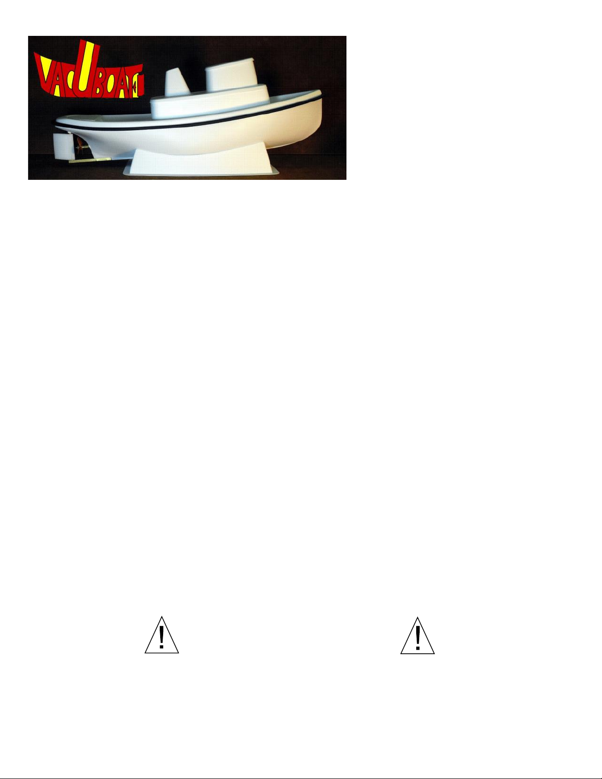
consequential damages. You may have other rights, which vary from state to state. Caution: Never leave the
boat in a hot car. It will melt!
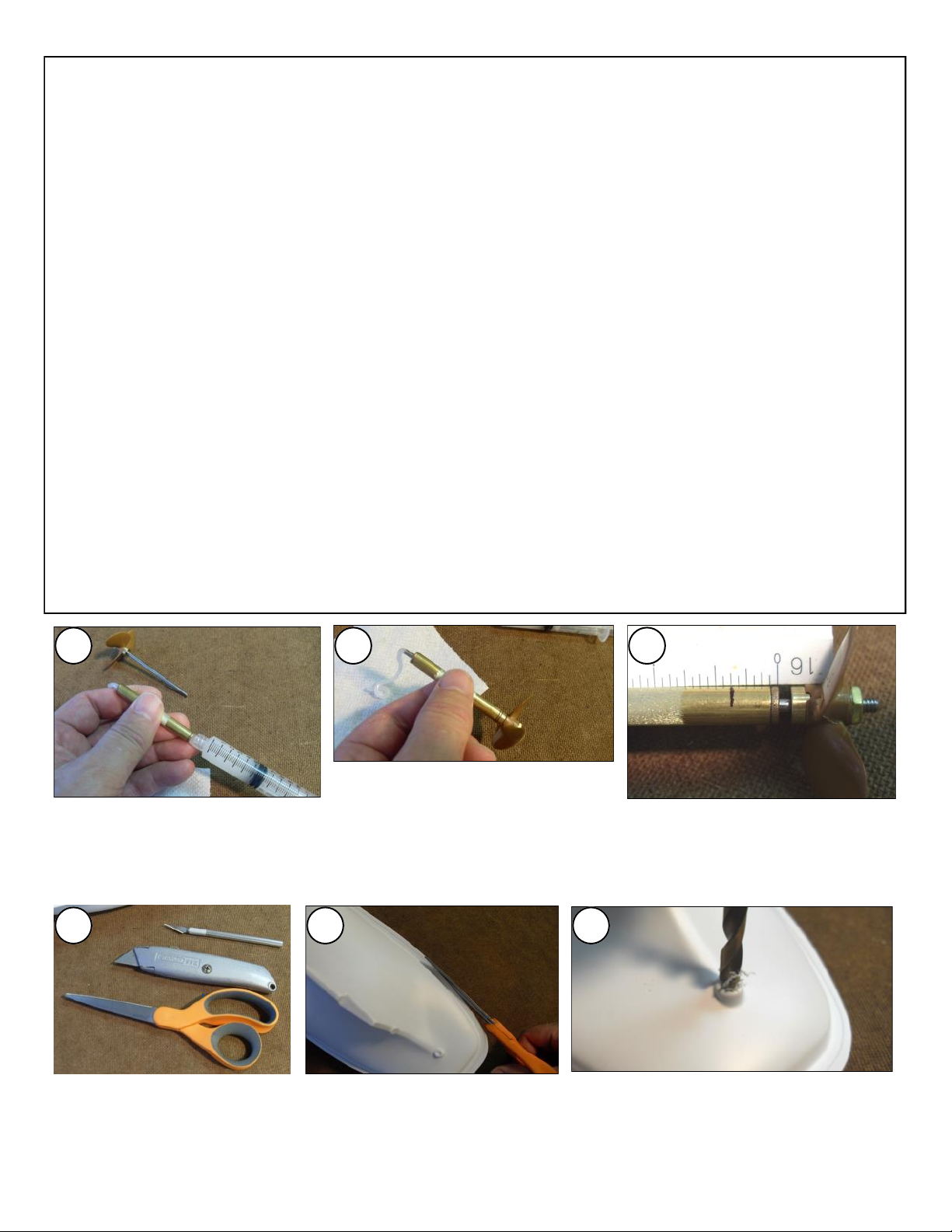
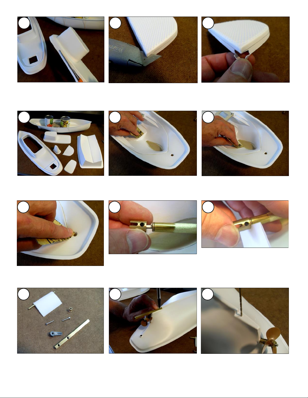
CUTTING PLASTIC: Adults only! A sharp pair of sewing scissors is best to trim around the parts. Cut through
sharp corners in the plastic with a hobby knife. While H.I.P.S. is tough, it will tear. When cutting out holes, as in
the top of the Cabin and through the rear hatch, score the opening with the tip of the hobby knife. (Just a deep
scratch.) Then trace the score 2 or 3 more times and you will cut through the plastic. As you cut through the
plastic, hold the knife at a side-angle to keep the blade from binding in the cut. Don’t hurry. Draw the blade
slowly along the plastic to prevent overcutting. Think about where the blade would go if it slipped. (Like, into
your leg or arm!)
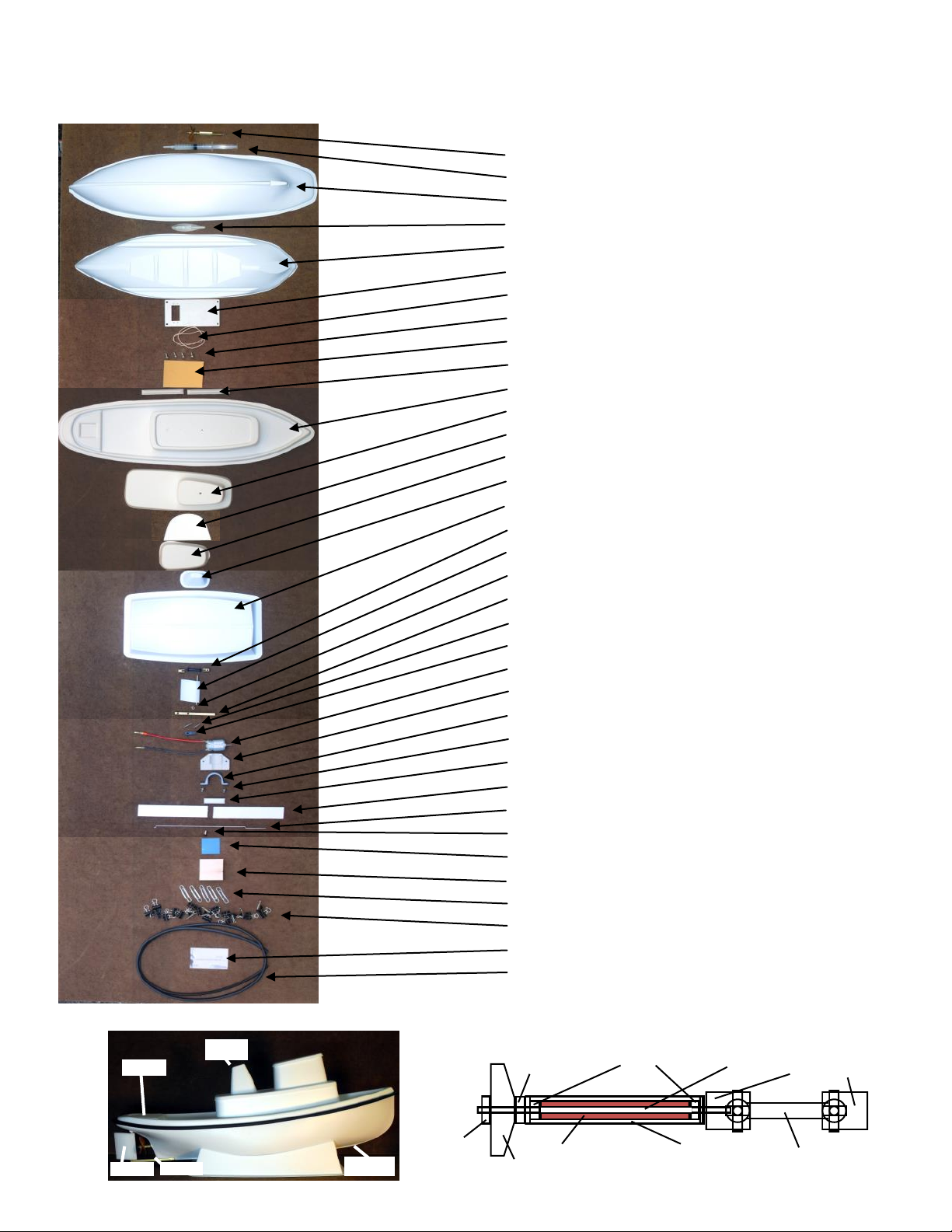
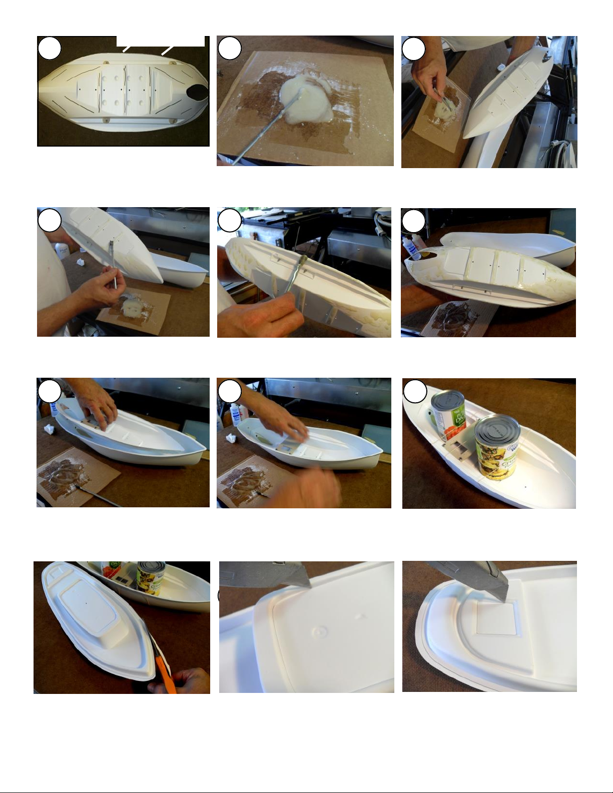
GLUE: You will need about two ounces of 30-Minute or “2-Ton” epoxy. Most 15-Minute or shorter-time
epoxies will break down over time with exposure to water. 30-Minute is waterproof and gives you more working-
time for this model. Epoxy is used for the rudder shaft, skeg reinforcement, rudder bearing & ballast weights.
Where specified, a filler should be added to make the epoxy less brittle, increase the volume, and to thicken it.
Dry plaster, talcum powder, or micro-spheres all work well. Mix the two parts of the epoxy together first. Then,
add the same volume of filler material and fold them together until blended. Medium CA (super glue) is best for
gluing the H.I.P.S. together when attaching the Hull to the Deck, the Pilot House Roof to the Pilot House and for
the Stack to the Deck. “Gorilla” brand Super Glue has a “medium” consistency and works well. If you are
inexperienced with CA Glue, those small metal tubes of Model Cement found where plastic model cars are sold,
either the regular kind or the “non toxic” type will work. Model cars are made of the same type of plastic as this
boat. However, because the sheet plastic is so thin, it will melt more easily if you use too much glue. CA provides
the strongest seam with less chance of weakening or melting the plastic but must be used in a well ventilated area.
Both CA and Model Cement are permanent. If you think you will ever want to separate the upper and lower hulls,
then glue them with epoxy. You will have to scuff the surfaces of plastic to help the epoxy bond to the plastic.
Gentle prying will separate the parts. Experiment with the glues using the scrap of plastic you cut from the top of
the deck. This scrap can be used for testing glues or paints. Glue them together and then try to tear them apart.
Sandpaper, rubber bands, clamps and other tools are included to help with assembly.
PAINT: Use spray paints that are labeled as safe for plastics. The short cans of “Hobby Enamel” found at your
hobby store, or spray paints safe for plastics like Krylon Fusion or Plasticote brands work best. When buying
them, if the lid isn’t sealed, remove the cap to see if someone “test sprayed” the can. If it has any paint residue on
the spray nozzle, don’t buy it. It is likely clogged because it was not properly cleared by inverting the can and
spraying the paint out of the nozzle. (See the can’s directions.) No sanding is necessary. Hobby Enamels, Fusion,
and Plasticote will bond with the H.I.P.S. well as long as the plastic is clean. Don’t get grease or oil on the plastic
as it can repel the paint. If in doubt, wash your hands with liquid detergent before handling the plastic. Buy a can
of Clear Hobby Enamel or Clear Krylon Fusion when you are getting the colors. It makes a great top coat on dull
metallic or dark colors that don’t gloss on their own. Test the colors on the scrap to see if a coat of clear is
necessary. NEVER USE LACQUER OR AUTOMOTIVE PAINTS ON H.I.P.S. PLASTIC. It will soften the
plastic and greatly shorten its life span and may completely melt the plastic. Avoid all tall spray cans like Krylon®
or other “household enamels”. They will damage the thinner areas of the sheet plastic. Don’t be fooled by test
spraying auto paint onto the scrap. They are thicker than the model parts and will be less affected. Avoid the short
cans of lacquer you will find at hobby stores. Ask for hobby enamel. I have listed additional painting tips at the
end of the manual.
2

BOW
(Front)
STERN CABIN
HULL
PILOT HOUSE
SKEG KEEL
RUDDER
HATCH
EXHAUST
STACK Prop
Shaft
Shaft Bearings
Stern TubeGrease
Prop
Prop
Nut
Drive
Dog
Dogbone
Motor-Shaft
Coupling Ends
3
PROP SHAFT ASSEMBLY
SYNTHETIC GREASE SYRINGE
HULL
SKEG REINFORCEMENT
HULL LINER
SERVO TRAY
3 RUBBER BANDS
4 STAINLESS SERVO TRAY SCREWS
100 GRIT SANDPAPER
SERVO TRAY SCREW REINFORCEMENT STRIPS
DECK
PILOT HOUSE
HATCH COVER
PILOT HOUSE ROOF
STACK
BOAT STAND
MOTOR-SHAFT COUPLING ASSY.
RUDDER
RUDDER BEARING
SKEG
SKEG SCREWS
RUDDER ARM & SET SCREW
MOTOR
MOTOR MOUNT
MOTOR CLAMP
STAINLESS MOTOR SCREWS
MOTOR-SHAFT ALIGNMENT CLIP
HOOK & LOOP FASTENER
STAINLESS RUDDER PUSHROD
E-Z CONNECTOR
HATCH WINDOW
WOOD BLOCK
PAPER CLIPS
20 CLAMPS
2 X 3 PLASTIC BAG EPOXY SHIELD
RUBBER RUB RAIL
DECAL SET (Not shown)
Vac-U-Tug Kit Contents
IN ORDER OF APPEARANCE:

Lube & Mark Prop Shaft
To complete the radio-controlled boat, you will need:
ADULT SUPERVISION, 2-Ton or 30-minute epoxy, medium CA glue, (Regular or non-toxic model
cement will work fine but CA “super glue” is needed for the end joint of the rubber rub rail) electric drill with
bit assortment, screwdrivers including a tiny Phillips screwdriver for servo screws, scissors, hobby knife or
Xacto® knife, ballast weights (a carton of 5,000 BB’s or lead shot work well), pencil, masking tape, light
sewing-machine oil, plastic compatible spray paint or non-toxic type brush or spray acrylic paints compatible
with plastic.
1. A 2-channel pistol (Recommended) or stick radio with one standard servo. AM, FM or 2.4 Ghz
(Recommended to avoid conflict with other boats, especially needed if you are building a rescue boat.).
2. An economical ESC Electronic Speed Control with forward and reverse. A waterproof ESC is not re-
quired. Read about ESCs on the vac-u-boat.com home page link.
3. A rechargeable battery. Either a 6-cell 7.2 volt NiMh Nickel Metal Hydride or a 2S 7.4 volt Lithium
Polymer battery. Each type of battery has different rules regarding safely charging them and their
charge-state when not in use and their safe storage. Consult the manufacturer or the internet for recom-
mendations for your type of battery. 7 or 8 cell NiMh (8.4 or 9.6 volts) or 3S LiPo (11.1 volts) can be
used for more power if your ESC is designed for the additional voltage.
4. A safe charger for your battery. Wall chargers or more expensive peak detection chargers will do fine.
Never charge a battery without constant supervision. Read the battery and charger instructions and
warnings. Never charge the battery in the model. Never leave the charger unattended.
RC radio sets usually come with a battery pack for 4 AA batteries. These will power the receiver and ser-
vos if you don’t have an ESC with Battery Eliminator Circuitry BEC. Most ESCs have the BEC feature.
This means that the large rechargeable battery that runs the motor will also power the receiver and servos
through the ESC when the ESC is plugged into the receiver. The ESC will have a switch that turns on and
off the power to the receiver. For most ESCs, you will not need the 4-AA battery pack.
Squeeze the synthetic grease into
the Stern Tube until it comes out
the other end.
Push the Prop Shaft into the stern
tube. This will push out the excess
grease. Wipe off the excess with a
paper towel. Be careful to keep any
grease off of the brass Stern Tube.
You will need sharp scissors
and a box cutter or hobby knife,
whichever you are the most
comfortable using.
Put a mark on the Stern Tube
about 3/8ths of an inch from
the end of the bearing.
Trim the Hull along the marked
line on it’s underside. The
plastic is thick for a stronger
hull. Use sharp scissors!
With a 1/4” drill bit, drill through the
Rudder Bearing hole. Use gentle pressure.
Let the drill slowly drill through the
plastic to avoid it splitting.
123
456
4
Trim The Hull

Round out the hole if necessary.
With a rocking motion, slice
through the Stern Tube hole as
shown. Cut down 2/3rds then cut
up 1/3rd to complete.
As you drill, check the alignment to
ensure the hole is in the center.
Sand the area inside the Hull at the stern
to help the epoxy bond the skeg
reinforcement to the Hull. Test fit the
skeg reinforcement into the hull.
789
10 11 12
13 15
16 17 18
5
Measure out two inch-wide
puddles of epoxy parts A & B.
14
After mixing, fold in the same volume
of filler material. I’m using Talcum
Powder. The filler makes the epoxy
less brittle after it cures.
Put the filled epoxy on the bottom
surfaces of the Skeg Reinforcement.
Put lots of filled epoxy in the
recess of the hull where the skeg
reinforcement will set.
Set the reinforcement into the stern
of the hull.
Press the Skeg Reinforcement into
the epoxy. Cover the reinforcement with the
squeezed-out epoxy.
Install Skeg Reinforcement
Sand all surfaces of the Skeg
Reinforcement. The skeg is the
square brass tube that supports
the bottom of the rudder.

Mark the outline of the flat oval at
the stern of the Hull Liner.
Score the oval along the line
until the oval separates from the
liner.
Set the Servo Tray into the Hull
Liner as shown. If needed, use 2
rubber bands to snug the liner.
With the Servo Tray slid against
the raised bumps on the liner,
mark the 4 holes with a pencil.
Drill 1/8 inch vent holes into the
liner on each side of the floor ribs
as shown.
These are the Servo Tray Screw
Reinforcing Strips. They provide a
better anchor for the screw threads.
Drill 3/32 inch holes at the 4
marked Servo Tray holes.
Trim any bits from the underside of
the drilled holes.
Mark the Reinforcing Strip
through the Hull Liner.
Hole the Reinforcing Strip under the
tray mount holes.
Tilt up the hull with a book to keep
the epoxy in place as it cures.
19 20 21
22 23 24
25 26 27
28 29 30
6
Trim the edges of the Hull Liner
along the marked line.
Trim The Hull Liner
Install the Servo Tray

Drill the Reinforcing Strips as
marked with a 3/32” drill.
Turn over the Hull Liner and sand
the areas that will contact the Hull.
Set the Hull Liner into the Hull.
Use a pencil to lightly mark the hull
along the top of the Liner.
The screws should pull the
Reinforcing Strip tight against the
Hull Liner.
Instead of waiting for the CA to
bond, go ahead and install the tray
and screws. The screws will hold
the strips in place.
Sand the area inside the Hull below
the marked line. Sand the areas around
the rudder and prop shaft holes.
Practice setting the Hull Liner into
the Hull for the next step.
If you are in a hurry, you can
CA the Liner. Otherwise, mix
another batch of epoxy. 1-1/2
inch circles.
Metal rods make great stirrers. With
them you can fold the epoxy over
and cleanly push it around.
Now you have a handle for the
Hull Liner.
Don’t forget the thin edges and
bottoms of the floor ribs.
31 32 33
34
Apply Medium CA (super glue) to one
strip. Hold the strip against the underside
of the rail with the holes aligned.
35 36
37 38 39
40 41 42
7
Glue in Hull Liner

Dab along the sharp edges. 30-
minute epoxy can gel in 10 min. You are ready to set the Hull Liner
into the hull.
If using CA, these lines mark
where you should put CA glue on
the Internal Tray before inserting it
into the Hull. Mix the epoxy and add filler. Find
the Epoxy Brush. Holding the Liner, apply the epoxy by
lightly dabbing the sanded areas.
It doesn’t have to be pretty. But, you
should work as fast as you can.
A couple of cans or similar weights
will help hold down the Liner until
the epoxy has cured.
Insert bow-first, trying to avoid
touching the sides of the Hull with
the Hull Liner.
While you are waiting on the Hull
epoxy to cure, trim the deck pieces. The Deck top recess is marked. Score
3-4 times and it will separate. Don’t
try to cut through the first time.
The rear hatch opening is marked
for trimming the same way. No
rush.
43 44 45
46 47 48
49 50 51
52 53 54
8
Press into place. If the sides of the Hull
are not making good contact with the
sides of the Liner, add rubber bands.
Put CA along the edge too.
Trim Deck & Superstructure
Use alcohol to
clean off stray
epoxy.

Sand the area where the motor and
motor mount will be glued. Sand all around the ballast and shaft
area.
Sand the rudder hole area if you
missed it earlier.
Fold a piece of paper and use it as a
spacer between the coupling end
and the stern tube. Tighten the two
set screws and remove the paper.
This should leave a small gap there.
Open the Rudder Package.
Take the brass Skeg and 2
screws.
Use a 3/32 inch drill to drill a
straight hole through the Hull
and Skeg Reinforcement.
Cut curves by taking shorter
snips. If the edge is uneven, you
can sand the cut edge.
Sharp corners should be started with
a razor using a rocking motion until
the blade cuts into the plastic.
Now break off the cut corner. Use
scissors to follow the trim line
marked on the Hatch Cover.
Place the Skeg on the hull, aligned
with the keel (bottom board) of the
hull. Mark ONLY the end screw hole.
55 56 57
58 59 60
All trimmed. The hull should be
set by now. Check the mixing
board to make sure.
61 62 63
64
Insert the Stern Tube Assembly into the
hull. Slide the 1/8 in Coupling End onto
the shaft. Note the location of the flat
on the shaft.
65 66
9
Install Prop Shaft Assembly
Install Rudder & Skeg

Insert the longer brass rod of the
rudder into the bearing. Slip the Skeg onto the rudder and
attach the bow-end screw into the
Skeg. Just snug the screw for now.
Align the Skeg with the Keel of the
Hull.
Press the Rudder Bearing into the
1/4 inch hole.
Rotate the Skeg aside, and drill
only into the white plastic, not
into the reinforcement yet.
Align the Skeg and tighten the front
screw. Now continue drilling into the
reinforcement, using the hole in the Skeg
as a guide to keep your drill centered.
Tighten both Skeg screws. The Rudder should turn freely
without binding. The Skeg and Rudder should align close
to this. It does not have to be exact.
Mark the 2nd hole then loosen the
first screw 2-3 turns.
67 68 69
70 71 72
73 74
Using a Skeg screw as a guide,
wrap a piece of tape on the drill to
make a depth gauge.
75
76 77
10
78
Drill until your “Depth Gauge” contacts
the Skeg. You should pull out the drill
once or twice during the drilling to
remove plastic from the drill bit.

The end of the motor shaft should
be flush with the bottom of the
Coupling.
Drill two 7/64 inch holes into the
marked dimples of the motor base.
Set the motor into the tray just as
shown. Screw on Motor Clamp &
tighten the screws.
Note the orientation of the
Coupling Ends in the Alignment
Clip. If needed, pull the ends out a
little and rotate them so they
contact the clip as shown.
This lets the Alignment Clip make
the best side contact with the
Coupling End. Repeat pressing the
Coupling Ends into the Clip shown
in step 84.
Rotate the Prop so see if the shafts
appear to be aligned. Center the
Motor Mount between the raised
side ridges of the Liner.
Mix a pair of 1 inch circles of
epoxy, but do not add the filler
yet.
Put a couple of drops of the epoxy at
the sides of the rudder bearing. Help it
run around the bearing. Keep the
epoxy off of the top of the bearing.
This is the Motor-Shaft Alignment
Clip. It will temporarily align the
Motor and Shaft together.
79 80 81
82 83 84
85 86
Set the Motor Assembly in place
and clip each Coupling End into
the Alignment Clip.
87
88 89
11
90
Check the mark on the Stern Tube.
3/8 inch from the end of the shaft
bearing. It should look like this.
Assemble Motor Assy to align Skeg
Unpack the Motor Package. You
can install the 3/32 in. Coupling
End to the motor shaft.

Now add lots of filler to the rest of
the mixed epoxy. Put the filled epoxy over the Prop
Shaft Assembly where it comes
through the Hull.
Push the epoxy under the Prop
Shaft Assembly to eliminate any
air bubbles under it.
Just enough to encircle the bearing
and fill the narrow gap between the
bearing and the Hull Liner.
Mix a smaller batch of filled epoxy.
Carefully apply a layer around the
rudder bearing & put the rest over
the Prop Shaft Assembly as shown.
Once the epoxy cures, carefully
slide off the motor and Alignment
Clip. Sand the bottom and bottom
edges of the Motor Mount.
Mix the last batch of filled epoxy.
Make sure the third layer is still
lower than the top of the bearing.
Put filled epoxy into the liner where
the Motor will sit. If the Servo Tray
is in your way, remove it. Put epoxy on the bottom of the
Motor Mount.
91 92 93
94
Check the shaft alignment. Confirm
the motor is still centered and the
mark on the side of the Prop Shaft is
still aligned.
95 96
97 98
Let this first coat of epoxy
“gel” (firm but not completely
cured). We will apply 2 more coats
in the next steps.
99
100 101
12
102
Test-Fit the motor to the Stern Tube
with the Dogbone between the
Coupling Ends.
Install Motor Assembly

From different viewing angles, the
Coupling Ends should appear
aligned. The Dogbone will have
about 1/16 inch of forward/rearward
play. (It will slide back and forth
between the couplings a little.) As
the Motor Mount epoxy cures, check
this alignment and Dogbone play
until the epoxy is cured.
Use a paper clip or wire to put a
droplet of oil on the rudder bearing at
the shaft.
Mount only the top rubber and
grommets on your Servo. Remove
the Servo Tray for the next step.
Set the Motor Assembly into the
Liner. Insert the Dogbone between
the Coupling Ends.
Install the 4 servo screws. Make sure
the Servo is oriented into the tray as
shown.
Re-install the Servo Tray. The stern
of the boat is on the right in this
photo.
Press the Rudder Arm onto the
Rudder Shaft. Align the rudder and
tighten one set screw against the
flat on the Rudder Shaft.
Cut the fuzzy “loop” side of the
Hook & Loop fastener and put on the
back of the Receiver and the
Electronic Speed Control.
Insert the bottom wired end of the
servo into the tray first as shown.
Slide the servo toward the wire.
103 105
106 107 108
109 110
Push down on the other end and
the Servo should snap into the
hole. You may have to wiggle the
servo a bit.
111
112 113
13
114
Put the Rudder Arm on the Pushrod
like this, with the rod inserted from
under the arm.
To align the Servo, we need to install
the electronics. Hook-side of Hook
& Loop is stuck to the Servo Tray.
1 Set Screw
Install Servo & Rudder Linkage

Connect the ESC, battery, & servos
from the instructions for your
electronics. Set transmitter steering.
adjustments to neutral.
Turn on the Transmitter first, then
the receiver using the switch on the
Electronic Speed Control. In this
case, the servo horn is angled.
Fix this by removing the servo
horn and rotating it to each arm
until you find one that leaves the
arm square to the servo body.
Now is the time for an Operational
Check. Turn on the Transmitter,
THEN the Receiver.
Pull the throttle trigger. The motor
should turn the shaft freely. The Rudder Arm and the Servo Horn
should be parallel to each other
as shown.
Attach the ESC and the Receiver
to the tray. The servo is channel 1,
the ESC is channel 2.
115 117
118 119 120
Align the rudder as shown. Now,
tighten the screw on the E-Z
Connector while holding the pushrod
next to it. Any further adjustments
can be made with the transmitter.
121 122
Return the servo horn to the servo.
Install the servo horn screw. Slide
the Rudder Pushrod into the hole
of the E-Z Connector.
123
124 125
14
126
Check the direction of the prop. Going
forward, it should be turning counter-
clockwise as seen from the back.
116
Install the E-Z Connector onto the
3rd hole from the center of the
servo arm as shown.
Turn the wheel of your transmitter to
see if the rudder works. This is a
LEFT turn of the wheel. If the rudder
is opposite, then reverse the
transmitter steering switch.

Cut 1/4” strips of hook & loop.
Lightly sand the underside of the
stack and apply CA. Press 40
seconds onto the Pilot House deck
supported by the wood block.
127 129
130 131 132
Stick the hook side to the hatch as
shown, away from the opening. Put
the fuzzy loop side on top and
remove paper from the adhesive.
Cut 4 squares each of Hook and
Loop material. Press together and
remove the tape from the Hook side.
133 134
There is a window for the hatch
opening. Do not install it yet.
135
136 137
15
138
Drill a small vent hole in the
center of the marked area.
128
Remove the Hatch Cover and
press the strips to set the adhesive.
I tested with a smaller battery. To
ballast the boat, I install the battery I
plan to run in the boat.
Sand the top of the Pilot House and
underside of the Pilot House Roof.
Glue together with CA.
Center the Stack on the deck of the
Pilot House. Lightly mark the
location in pencil.
Align and press the hatch in place.
This will cause the loop side to
stick to the hatch.
Stick the Hook & Loop squares on the
front and rear of the Cabin as shown.
Peel tape. Set Pilot House on Cabin to
adhere the Loop to the Pilot house.
Remove Pilot House and press the
Hook & Loop to set the adhesive.
Assemble Superstructure

Add the epoxy to the ballast and
knead to mix them together.
139 141
142 143
The recommended Total Weight for
the completed model is 63 - 66 oz.
144
Float the boat in a tub or container of
water. It will be top heavy during this.
Pour front ballast bb’s into a plastic
bag. Mix 2 one-inch circles of epoxy
parts A & B and add to the bag. Use
NO FILLER with this epoxy.
145 146
Use a small magnet or spoon to
remove or adjust the ballast. To little
is easier to fix than too much.
147
148 149
16
150
Mix two 1-1/2 inch circles of epoxy
with no filler. The rear ballast is a
often a little larger than the front.
Mark the center of the curve of the
bow on a piece of tape.
140
The bow should set just below
your mark. The stern, about 1/8”
below the top of the rudder.
Still in the bag, press the ballast to
shape it into the hull forming a flat
topped triangle.
Clamp the 2 inch x 3 inch plastic
bag around the Coupling and Stern
Tube to keep out epoxy.
Using bottoms of foam or plastic
cups, add ballast to the front and
rear gradually.
Knead the bb’s with the epoxy until
they are evenly coated. Set the bag in
the bow of the Hull.
See page 19 for more information.
Install Ballast for the Boat
With battery and all gear installed,
temporarily clamp the Deck to the
Hull with four clamps.

Pour it evenly on each side avoiding
the Coupling.
Lightly but evenly sand the mating
sides of the Hull flange and Deck
flange. Apply a bead of CA around
the flange of the hull. Place the
three paper clips as shown.
151 153
154 155 156
Arrange the ballast with a paper clip
with a bend at the end to reach under
the Coupling and Prop Shaft .
Cut 2 pieces of Hook & Loop. Stick
them to the front ballast as shown.
157 158
After it is fully cured, overnight,
remove the plastic bag from the
front ballast.
159
160 161
17
162
Bend 3 paper clips as shown. They
will keep the stern of the Deck from
sticking to the Hull too soon.
152
Remove the Coupling cover. While
the epoxy is still wet, check the
arrangement of the front ballast.
Cut the corner of the bag and
squeeze the ballast into the stern.
Arrange the 20 clips around the Hull
evenly. Practice clamping the Deck
to the Hull. Start at the bow and...
Arrange the ballast evenly on each
side, with a open gap under the
Coupling and Prop Shaft end.
Peel off the paper tape and stick the
ballast into the bow. It can now be
removed easier to adjust its weight.
work your way rearward. Don’t
clamp the stern until last. If you
clamp the front and back ends, the
middle will not meet.
Glue the Deck to the Hull

After 2-3 minutes, move the clamps
to the spaces between them.
Hold tight for one minute. Check
under the glued ends and if not
together, hold that spot too.
163 165
166 167 168
Engage the center of the Rub Rail on
the Stern. Without pulling hard, run
it toward the bow on each side.
169 170
Tape the edges fully. This gives
you access to the Rudder Arm and
to the Prop Shaft Coupling.
171
172 173
18
174
Apply a little CA to one end. Using
the Deck/Hull flange as a guide, roll
the ends together and hold.
164
While you are waiting on the Deck/
Hull joint to cure, tape the rear
hatch in place.
At the bow, gently pull it around the
bow and start a vertical cut with a
hobby knife.
Notice the clamps are not jammed
against the hull. They are centered
on the flange. A few final clamps
may need to stay on longer to bond.
This bend will help the Rub Rail open
and engage the flange of the hull. No
need to glue it. It will stay in place.
Continue the cut over the wood
block or table. Hold it carefully to
ensure a straight cut. Repeat for the
other end.
Align the bow-center and clamp.
Then, work rearward left and right
aligning the outside edges of the Hull
and Deck flanges as you go.
Look for spots that are not stuck
together tight and clamp them.
Install Rub Rail

MEASURE
EQUIVALENTS Daisy
BB’s #9 lead
bird shot
# per ounce 22 -
Level Tablespoon 2.2oz. 3.0oz.
1/4 cup level 9.2oz. 13.3oz.
1/3 cup level 11.6oz. 16.3oz.
175 177
178 179
19
176
Apply decals after the paint has
cured.
Your tug is finished and ready to be
painted.
If you mess up the Rub Rail end
glue, you can trim off 1/8 inch and
try again. Get the extra length you
need by pulling off the rub rail down
each side, and re-installing with a
little pull as you go to stretch the
length of the rub rail a little. You can
also practice on the ends you cut off. Re-install the Rub Rail starting with the
(front) bow end and work backwards.
The rub rail can be removed for
painting or repairs.
PAINTING TIPS: Click the Painting Tips link on the Vac-U-Boat home-page for more help. It is easy to
get professional results with a spray can if you know the basics. The same rules apply to spray cans as apply to
professional painters using spray equipment. It will take 2 to 3 coats of most hobby paints to give a good even
color. Never try to get full coverage with the first coat. It will run every time! You should be able to see through
the first coat. The best tip about any kind of spray paint is to let the paint “flash” between coats. A coat of
paint has “flashed” when it is dry to the touch. Don’t touch the boat. Touch the masking paper or somewhere
where a fingerprint won’t show in case you touched it too soon. Hobby enamel will take 5 to 15 minutes to flash
depending on the temperature. Different colors can take different times to flash. A coat that has flashed properly
will support the next coat and prevent it from dripping. The second coat will take longer to flash than the first. Be
patient! Practice on a scrap stood on it’s end. Your goal is to get coverage without runs. Avoid spraying enamel
on very humid days. Humidity can cause the paint to “blush” leaving a cloudy appearance to dark colors. After
the spray paint has fully dried, you can apply the decals. “Non-toxic” model paints are safest to brush on, for the
painter and the boat. Read the spray can. Some types must be recoated before X hours or after X days to avoid
wrinkling the old layer with the new layer. Temperature and humidity are important.
Mask the Drive Dog & Shaft Bearing near the Prop to keep paint from gumming them up. If you paint the
Boat Stand, let it cure 3 days before using it. Otherwise, it may stick to the boat. A couple of strips of felt along
the top of the Boat Stand will prevent sticking and scratching the hull.
DECALS: Apply only after the paint has fully cured. Place the boat on it’s stand. The stand holds the boat at
a bow-up angle just like it sits in the water. Make sure that doors or square openings are vertical to this position.
Otherwise, if you placed the door decals parallel to the floor, they would be angled toward the stern when the boat
is in the water. Cut out the desired decal from the assortment. Separate the paper backing from the front tissue.
The decal will adhere to the front tissue. Place the decal on the hull and smooth it with your fingernail. Peel off
the front tissue paper. The decal set includes several types of Doors, Portholes, Scuppers (deck drains), exterior
weatherproof Lights (small ovals), Ladders, Ladder Rungs, retracted Anchors, and two V’s for “Vac-U-Boat” to
put on the Stack. The hinge-side of the doors point toward the bow of the boat. You will find left and right doors
in the set. See our website for examples.
All Done!

ANTENNA: Most 2.4 Gigahertz radios do not have a visible antenna, or have a very short one. If you are
using an AM or FM radio, take the end of the antenna and tape it on the upper inside of the pilot house for good
reception.
WATERPROOFING - FLOTATION: Be sure to tape the clear plastic hatch window in place to prevent
leaks. There is plenty of room in the Bow for flotation. An inflated Ziplock® bag with the opening pressed and
taped closed, makes a nice form-fitting float.
REPAIR: In swimming pools, long hair can wind up on the prop shaft between the Drive Dog and the Stern
Tube Bearing. If this happens, the shaft will bind and slow or stop turning. To repair, insert needle-nosed pliers
through the rear hatch opening and lightly grasp the Motor-Shaft Coupling End to block the shaft rotation. Use a
1/4 inch wrench to loosen the Prop Nut several turns. Unscrew the Prop & Drive Dog 3-4 turns by turning the
Prop. Remove the hair and re-tighten the Prop with Drive Dog & install the Prop Nut. Don’t store the boat in
direct sunlight. This will shorten the life of the plastic. Re-Tape the rear hatch opening afterwards.
MAINTENANCE: Before running, place a droplet of light oil between the Drive Dog and the Stern Tube
Bearing. Rotate the prop to distribute the oil & wipe off the excess.After running, tilt the boat toward the Bow
and blot out any water that was hiding under the floor. Even if you find no water, leave the Pilot House off for a
day to allow any moisture to dry. The synthetic grease in the stern tube will keep your boat water-tight for years.
It needs to be refilled only if you see water leaking into the boat through the inside of the stern tube. To access
and relube the Stern Tube, remove in this order: Rudder Arm, Skeg, Rudder, Servo Tray, Motor, Dogbone, Motor
-Shaft Coupling on the Prop Shaft. Slide out the Prop Shaft. Squirt new Stern Tube Grease into the Stern Tube
from the outside. Catch the overflow with a napkin on the inside. Push the Prop Shaft into the Stern Tube catching
the additional grease that will be pushed into the boat. Reassemble all parts. You will have to find the flat on the
Prop Shaft by “feel” when you reinstall and properly space the Prop Shaft’s Coupling. Hold the Dogbone in place
with a pair of needle nosed pliers through the rear hatch opening while installing the motor.
The set of decals will help trim out your Vac-U-Tug for a realistic look.
Now go find some water and have fun!
Copyright © 2001 - 2018 Philip Pace, d.b.a. Vac-U-Boat
Port Holes
Windows
Pilot Windshield
Left & Right
Doors
Ladders
Doors
Scuppers (deck
drains)
Wall Vents
Anchor
Stack Marking
Other Vac-U-Boat Toy manuals

Vac-U-Boat
Vac-U-Boat Vac-U-Vee Jr. User manual

Vac-U-Boat
Vac-U-Boat Vac-U-Soling Lower Hull Kit User manual

Vac-U-Boat
Vac-U-Boat Combat Vac-U-Gearing User manual

Vac-U-Boat
Vac-U-Boat Vac-U-Fletcher User manual

Vac-U-Boat
Vac-U-Boat Vac-U-Cracker User manual

Vac-U-Boat
Vac-U-Boat Combat Vac-U-Fletcher User manual
Popular Toy manuals by other brands

LEGO
LEGO STAR WARS 75153 Building instructions

ScaleTrains
ScaleTrains RIVET COUNTER SD38-2 product manual

REVELL
REVELL Eurocopter EC145 MEDSTAR/Police Assembly manual

Quest Engineering
Quest Engineering Flying ModelRocket KitL Assembly instructions

LEGO
LEGO 4950 System Assembly guide

Joysway
Joysway DRAGONFORCE 65 instruction manual