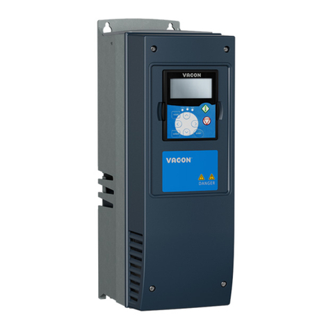
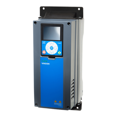
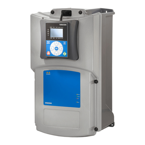
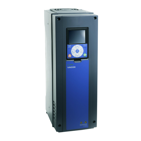
Vacon 100 flow Instructions for use

vacon 100 flow
ac drives
application manual
®


vacon • 0
TABLE OF CONTENTS
Document: DPD01083C
Version release date: 12.11.13
Corresponds to software package FW0159V008.vcx
1. Vacon®100 FLOW - Quick startup guide ..........................................................6
1.1 Keypad of Vacon®100 FLOW .............................................................................................6
1.1.1 Keypad buttons...................................................................................................................6
1.1.2 Display................................................................................................................................6
1.2 First startup .......................................................................................................................8
1.3 Fire mode wizard .............................................................................................................10
1.4 Application wizards ..........................................................................................................11
1.4.1 Standard and HVAC application wizards .........................................................................12
1.4.2 PID control application wizard.........................................................................................12
1.4.3 Multipump (single drive) application wizard ...................................................................14
1.4.4 Multipump (multidrive) application wizard......................................................................16
1.5 Description of the applications ........................................................................................18
1.5.1 Standard and HVAC applications .....................................................................................18
1.5.2 PID control application ....................................................................................................24
1.5.3 Multipump (single drive) application ...............................................................................30
1.5.4 Multipump (multidrive) application .................................................................................39
2. User interfaces on Vacon®100 FLOW ............................................................54
2.1 Navigation on keypad .......................................................................................................54
2.2 Vacon graphical keypad ...................................................................................................56
2.2.1 Using the graphical keypad .............................................................................................56
2.3 Vacon text keypad ............................................................................................................64
2.3.1 Keypad display .................................................................................................................64
2.3.2 Using the text keypad.......................................................................................................65
2.4 Menu structure ................................................................................................................68
2.4.1 Quick setup.......................................................................................................................69
2.4.2 Monitor .............................................................................................................................69
2.5 Vacon Live ........................................................................................................................71
3. Monitoring menu............................................................................................72
3.1 Monitor group...................................................................................................................72
3.1.1 Multimonitor.....................................................................................................................72
3.1.2 Trend curve ......................................................................................................................72
3.1.3 Basic.................................................................................................................................75
3.1.4 I/O .....................................................................................................................................76
3.1.5 Temperature inputs .........................................................................................................76
3.1.6 Extras and advanced ........................................................................................................77
3.1.7 Timer functions monitoring .............................................................................................80
3.1.8 PID controller monitoring................................................................................................80
3.1.9 External PID controller monitoring .................................................................................81
3.1.10 Multipump monitoring .....................................................................................................81
3.1.11 Maintenance counters .....................................................................................................82
3.1.12 Fieldbus data monitoring.................................................................................................83
4. Parameters menu ..........................................................................................84
4.1 Group 3.1: motor settings ................................................................................................84
4.1.1 Motor nameplate parameters..........................................................................................84
4.1.2 Motor control settings......................................................................................................85
4.1.3 Motor limit settings..........................................................................................................86
4.1.4 Open loop settings ...........................................................................................................87
4.2 Group 3.2: Start/Stop setup .............................................................................................89
4.3 Group 3.3: references ......................................................................................................90
4.3.1 Frequency reference parameters ...................................................................................90

vacon • 1
Tel. +358 (0) 201 2121 • Fax +358 (0)201 212 205
4.3.2 Preset frequencies...........................................................................................................92
4.3.3 Motor potentiometer parameters....................................................................................93
4.3.4 Flushing parameters .......................................................................................................93
4.4 Group 3.4: ramps and brakes setup ................................................................................94
4.4.1 Ramp 1 setup ...................................................................................................................94
4.4.2 Ramp 2 setup ...................................................................................................................94
4.4.3 Start magnetisation parameters .....................................................................................95
4.4.4 DC brake parameters ......................................................................................................95
4.4.5 Flux braking parameters .................................................................................................95
4.5 Group 3.5: I/O configuration.............................................................................................96
4.5.1 Digital input settings ........................................................................................................96
4.5.2 Analogue inputs ...............................................................................................................98
4.5.3 Digital outputs, slot B (standard)...................................................................................100
4.5.4 expander slots C, D and E digital outputs .....................................................................101
4.5.5 Analogue outputs, Slot A (standard)..............................................................................102
4.5.6 Expander slots C,D and E analogue outputs .................................................................103
4.6 Group 3.6: fieldbus data mapping..................................................................................104
4.7 Group 3.7: prohibit frequencies .....................................................................................105
4.8 Group 3.8: supervisions .................................................................................................105
4.9 Group 3.9: protections ...................................................................................................107
4.9.1 General protections settings .........................................................................................107
4.9.2 Motor thermal protections settings...............................................................................108
4.9.3 Motor stall protection settings ......................................................................................108
4.9.4 Underload (dry pump) protection settings ....................................................................109
4.9.5 Quick stop settings.........................................................................................................109
4.9.6 Temperature input fault 1 settings................................................................................110
4.9.7 Temperature input fault 2 settings................................................................................111
4.9.8 AI low protection ............................................................................................................112
4.10 Group 3.10: automatic reset ..........................................................................................113
4.11 Group 3.11: application settings ....................................................................................114
4.12 Group 3.12: timer functions ...........................................................................................115
4.13 Group 3.13: PID controller 1 ..........................................................................................117
4.13.1 Basic settings.................................................................................................................117
4.13.2 Setpoints ........................................................................................................................120
4.13.3 Feedback settings ..........................................................................................................122
4.13.4 Feedforward settings.....................................................................................................123
4.13.5 Sleep function Settings ..................................................................................................124
4.13.6 Feedback Supervision parameters ...............................................................................124
4.13.7 Pressure loss compensation parameters.....................................................................125
4.13.8 Soft fill Settings..............................................................................................................126
4.13.9 Input pressure supervision ............................................................................................127
4.13.10Sleep - no demand detection........................................................................................128
4.14 Group 3.14: external PID controller ..............................................................................129
4.14.1 Basic settings for external PID controller.....................................................................129
4.14.2 External PID controller, setpoints .................................................................................130
4.14.3 Feedbacks ......................................................................................................................131
4.14.4 Feedback supervision ....................................................................................................131
4.15 Group 3.15: multipump ..................................................................................................132
4.15.1 Multipump parameters ..................................................................................................132
4.15.2 Interlock signals.............................................................................................................134
4.15.3 Overpressure supervision parameters..........................................................................135
4.15.4 Pump running time counters.........................................................................................135
4.15.5 Advanced settings ..........................................................................................................135
4.16 Group 3.16: maintenance counters ...............................................................................136
4.17 Group 3.17: fire mode ....................................................................................................137


vacon • 2
4.18 Group 3.18: motor preheat parameters ........................................................................138
4.19 Group 3.19: drive customiser.........................................................................................139
4.20 Group 3.21: pump control ..............................................................................................140
4.20.1 Auto-cleaning parameters.............................................................................................140
4.20.2 Jockey pump parameters ..............................................................................................141
4.20.3 Priming pump parameters ............................................................................................141
4.20.4 Anti-blocking parameters..............................................................................................141
4.20.5 Frost protection parameters .........................................................................................143
5. Diagnostics menu.........................................................................................144
5.1 Active faults....................................................................................................................144
5.2 Reset faults ....................................................................................................................144
5.3 Fault history ...................................................................................................................144
5.4 Total counters ................................................................................................................145
5.5 Trip counters..................................................................................................................146
5.6 Software info ..................................................................................................................146
6. I/O and hardware menu ...............................................................................147
6.1 Basic I/O .........................................................................................................................147
6.2 Option board slots ..........................................................................................................148
6.3 Real time clock...............................................................................................................148
6.4 Power unit settings ........................................................................................................149
6.5 Keypad............................................................................................................................150
6.6 Fieldbus..........................................................................................................................151
7. User settings, favourites and user level menus...........................................152
7.1 User settings ..................................................................................................................152
7.1.1 Parameter backup .........................................................................................................152
7.2 Favourites.......................................................................................................................153
7.3 User levels .....................................................................................................................153
8. Monitoring value and parameter descriptions .............................................155
8.1 Monitoring value descriptions .......................................................................................155
8.2 Parameter descriptions .................................................................................................156
8.3 Motor settings ................................................................................................................157
8.3.1 I/F start function ............................................................................................................164
8.4 Start/Stop setup .............................................................................................................165
8.5 References .....................................................................................................................172
8.5.1 Frequency reference......................................................................................................172
8.5.2 Preset frequencies.........................................................................................................172
8.5.3 Motor potentiometer parameters..................................................................................174
8.5.4 Flushing parameters .....................................................................................................175
8.6 Ramps and brakes setup ...............................................................................................176
8.7 I/O configuration ............................................................................................................178
8.7.1 Programming of digital and analogue inputs................................................................178
8.7.2 Default assignments of programmable inputs .............................................................184
8.7.3 Digital inputs ..................................................................................................................185
8.7.4 Analogue inputs .............................................................................................................185
8.7.5 Digital outputs................................................................................................................189
8.7.6 Analogue outputs ...........................................................................................................191
8.8 Prohibit frequencies.......................................................................................................194
8.9 Supervisions...................................................................................................................196
8.9.1 Motor thermal protections.............................................................................................196
8.9.2 Motor stall protection ....................................................................................................199
8.9.3 underload (dry pump) protection...................................................................................199
8.10 Automatic reset..............................................................................................................204
8.11 Timer functions ..............................................................................................................205
8.12 PID controller 1 ..............................................................................................................208

vacon • 3
Tel. +358 (0) 201 2121 • Fax +358 (0)201 212 205
8.12.1 Feedforward...................................................................................................................208
8.12.2 Sleep function ................................................................................................................209
8.12.3 Feedback supervision ....................................................................................................211
8.12.4 Pressure loss compensation .........................................................................................212
8.12.5 Soft fill ............................................................................................................................213
8.12.6 Input pressure supervision ............................................................................................215
8.12.7 Sleep - no demand detection function...........................................................................217
8.13 Multipump function........................................................................................................219
8.13.1 Multipump (multidrive) commissioning checklist.........................................................219
8.13.2 System configuration .....................................................................................................221
8.13.3 Interlocks .......................................................................................................................227
8.13.4 Feedback sensor connection in a multidrive system....................................................227
8.13.5 Overpressure supervision..............................................................................................235
8.13.6 Pump running time counters.........................................................................................236
8.14 Maintenance counters ...................................................................................................239
8.15 Fire mode .......................................................................................................................240
8.16 Motor preheat function ..................................................................................................242
8.17 Pump control..................................................................................................................243
8.17.1 Auto-cleaning.................................................................................................................243
8.17.2 Jockey pump ..................................................................................................................245
8.17.3 Priming pump.................................................................................................................246
8.17.4 Anti-blocking function....................................................................................................247
8.17.5 Frost protection..............................................................................................................247
8.18 Counters.........................................................................................................................248
9. Fault tracing.................................................................................................253
9.1 Fault appears .................................................................................................................253
9.2 Fault history ...................................................................................................................254
9.3 Fault codes.....................................................................................................................255
10. Appendix 1 ...................................................................................................264
10.1 Default parameter values according to the selected application .................................264

vacon • 4
About this manual
This manual is copyright of Vacon®Plc. All Rights Reserved.
This manual describes the features and use of Vacon®100 FLOW. The manual has been compiled
in accordance with the menu structure of the drive (chapters 1 and 3-7):
•Chapter 1, Quick Startup Guide, gives information on
- How to get started with the keypad
- How to select the application configuration
- How to quickly set up the selected application
- The applications with examples
•Chapter 2, User Interfaces, gives information on
- The keypad in detail, the views, keypad types, etc.
- Vacon Live
- The onboard fieldbus functionality
•Chapter 3, Monitoring menu, gives detailed information on the monitoring values.
• Chapter 4, Parameter menu lists all the parameters of the drive
•Chapter5presents the Diagnostics menu
•Chapter6presents the I/O and Hardware menu
•Chapter7presents the User settings, favourites and user level menus
• Chapter 8, Parameter descriptions, gives further information on
- Parameters and their use
- Digital and analogue input programming
- Application-specific functions
• Chapter 9, Fault tracing, gives information on
- The faults and their causes
- Resetting the faults
•Chapter 10, Appendix gives information on the different default values of the applications
NOTE! This manual includes a large amount of parameter tables. Below you can find the column
names and their explanations:
Figure 1.
NOTE! You can download the English and French product manuals with applicable safety,
warning and caution information from www.vacon.com/downloads.
REMARQUE Vous pouvez télécharger les versions anglaise et française des manuels produit
contenant l’ensemble des informations de sécurité, avertissements et mises en garde
applicables sur le site www.vacon.com/downloads.
Value preset
by factory
Short description
of parameter values
and/or its function
9434_uk
Index Min Max Unit Default ID DescriptionParameter
More information
on this parameter
available later in
the manual.
Location indication
on the keypad;
Shows the operator
the parameter number
Name of the
parameter
Minimum value
of the parameter
Maximum value
of the parameter
ID number of
the parameter
Unit of parameter
value; Given if
available

vacon • 5
Tel. +358 (0) 201 2121 • Fax +358 (0)201 212 205
Specific functions of Vacon®100 FLOW AC drive
Features
•Extensive wizards for start-up, Standard, HVAC, PID-control, Multipump (Single drive and
Multidrive) and Fire Mode used to facilitate commissioning
•FUNCT button for easy change between Local (keypad) and Remote control place. The
remote control place is selectable by parameter (I/O or Fieldbus)
• 8 preset frequencies
•Motor potentiometer functions
• Flushing function
•2programmableramp times, 2 supervisions and 3 ranges of prohibited frequencies
•Quickstop
•Control page for easy operation and monitoring of the most essential values.
•Fieldbus data mapping
•Automaticreset
•Differentpre-heat modes used to avoid condensation problems
• Maximum output frequency 320Hz
•Real-time clock and timer functions available (optional battery required). Possible to
programmme 3 time channels to achieve different functions on the drive (e.g. Start/Stop and
Preset frequencies)
•External PID-controller available. Can be used to control e.g. a valve using the AC drive's I/
O
•Sleep mode function which automatically enables and disables drive running with user
defined levels to save energy.
•2-zone PID-controller (2 different feedback signals; minimum and maximum control)
•Two setpoint sources for the PID-control. Selectable with digital input
• PID setpoint boost function
•Feedforward function to improve the response to the process changes
• Process value supervision
• Multipump control for Single drive and Multidrive systems
•MultimasterandMultifollowermodes in Multidrive system
• Real-time clock based multipump alternation
•Maintenance counter
•Pump control functions: Autochange, Priming Pump Control, Jockey Pump Control, Pump
Impeller Auto-Cleaning, Anti-blocking, Pump Input Pressure Supervision and Frost
Protection function

Vacon®100 FLOW - Quick startup guide vacon • 6
1. VACON®100 FLOW - QUICK STARTUP GUIDE
1.1 Keypad of Vacon®100 FLOW
The control keypad is the interface between the Vacon®100 AC drive and the user. With the control
keypad it is possible to control the speed of a motor, to supervise the state of the equipment and to
set the AC drive's parameters.
There are two keypad types you can choose for your user interface: Keypad with graphical display
and Text keypad.
See a detailed description on operating the keypad in chapter 2.
1.1.1 Keypad buttons
The button section of the keypad is identical for both keypad types:
Figure 2.
1.1.2 Display
The keypad display indicates the status of the motor and the drive and any irregularities in the
motor or drive functions. On the display, the user sees information about the drive and
the present
location in the menu structure and the item displayed.
Graphical display:
Figure 3.
FUNCT
9086.emf
Scroll menu up
Increase value
Scroll menu down
Decrease value
Move cursor left Move cursor right
Move backward in menu
Exit edit mode
Reset faults with long press Change control place
Access control page
Change direction
See ch. 2.4.1.3 for
more information
Stop button Start button
Enter active level/item
Confirm selection
Enter edit mode
Bypass property page
9159.emf
Main Menu
Quick Setup
( 17 )
Parameters
( 12 )
STOP READY I/O
ID: M1
( 5 )
Monitor
Status field
STOP/RUN
Direction ALARM
Status field
READY/NOT READY/FAULT Control place:
PC/IO/KEYPAD/FIELDBUS
Activated group/item:
Press OK to enter
Number of items
in the group
Location field
(Parameter ID number and
current menu location

1
vacon • 7 Vacon®100 FLOW - Quick startup guide
Tel. +358 (0) 201 2121 • Fax +358 (0)201 212 205
If the text on the text line is too long to fit in the display, the text will scroll from left to right to show
the whole text string:
Text display:
Figure 4.
9167.emf
Indicators:
Status
Indicators:
Alarm, Fault
Indicators:
Direction
Indicators:
Control place
Group or parameter
name
Menu location

Vacon®100 FLOW - Quick startup guide vacon • 8
1.2 First startup
After the drive has been powered up, Startup Wizard will be initated.
In the Startup Wizard, you will be asked for the essential information needed by the drive to start
controlling your process.
Select ‘
Yes’
and push OK. If you select ‘No’ the drive will exit the wizard.
NOTE! If you select ‘No’ and push OK, you will have to set all parameter values manually.
NOTE! If you change the value of P1.2 Application (ID 212) later on the graphical keypad, the wizard
will guide you from step 8 to step 17 and jump then to the selected application wizard.
1Language selection (P6.1) Depends on language package
2Daylight saving*(P5.5.5)
* These questions appear if battery is installed
Russia
US
EU
OFF
3Time* (P5.5.2) hh:mm:ss
4Year* (P5.5.4) yyyy
5Date* (P5.5.3) dd.mm.
6Run Startup Wizard? Yes
No
7Select preset application configu-
ration (P1.2 Application (ID 212))
Standard
HVAC
PID Control
Multipump (Single drive)
Multipump (Multidrive)
8Select P3.1.2.2 Motor Type
(according to nameplate)
PM Motor
Induction Motor
9Set value for P3.1.1.1 Motor
Nominal Voltage (according to
nameplate)
Range: Varies
10 Set value for P3.1.1.2 Motor
Nominal Frequency (according to
nameplate)
Range: 8.00...320.00 Hz
11 Set value for P3.1.1.3 Motor
Nominal Speed (according to
nameplate)
Range: 24...19200
12 Set value
for
P3.1.1.4
Motor
Nominal Current
Range: Varies
13
Set
value
for
P3.1.1.5
Motor Cos
Phi
Range: 0.30-1.00

1
vacon • 9 Vacon®100 FLOW - Quick startup guide
Tel. +358 (0) 201 2121 • Fax +358 (0)201 212 205
If ‘
Induction Motor
’ has been selected in step 8, steps 9 - 13 appear. If ‘
PM Motor
’ has been selected,
steps 9 - 12 appear and the wizard will jump to step 14 after them.
If you select ‘
Yes’
and push the OK button you will be taken to the application wizard according to
the selection you made in step 7.
If you select ‘No’ and push OK, the wizard will stop and you will have to set all parameter values
manually.
Now the Startup Wizard is completed.
The Startup Wizard can be re-initiated by activating the parameteter P6.5.1 Restore factory
defaults OR by choosing Activate for parameter B1.1.2 Startup Wizard.
14
Set
value
for
P3.3.1.1
Minimum
Frequency Reference
Range: 0.00...P3.3.1.2 Hz
15
Set
value
for
P3.3.1.2
Maximum
Frequency Reference
Range:P3.3.1.1...320.00 Hz
16 Set value for P3.4.1.2
Acceleration Time 1
Range: 0.1...3000.0 s
17 Set value for P3.4.1.3
Deceleration Time 1
Range: 0.1...3000.0 s
18 Run Application Wizard? Yes
No

Vacon®100 FLOW - Quick startup guide vacon • 10
1.3 Fire mode wizard
NOTE! THE WARRANTY IS VOID, IF THE FIRE MODE FUNCTION IS ACTIVATED.
Test Mode can be used to test the Fire Mode function without voiding the warranty. Read important
information about the password and warranty issues in chapter 8.13, before you proceed.
Fire Mode Wizard is intended for easy commissioning of the Fire Mode function. The Fire Mode
Wizard can be initiated by choosing Activate for parameter 1.1.2 in the Quick setup menu.
If ‘Fire Mode Frequency’ is not selected for Fire Mode frequency source, go to step 3.
If ‘Open Contact’ is selected, go to step 5. If ‘Close Contact’ is selected, go to step 4 and skip step 5.
The Fire Mode Wizard is ready.
1
Select the Fire Mode frequency
source (P3.17.2).
Fire Mode Frequency
Preset Frequencies
Keypad Reference
Fieldbus
Analogue Input 1
Analogue Input 2
Analogue Input 1 + Analogue Input 2
PID 1 Reference
Motor Potentiometer Reference
Block 1-10 Out
2Set the value for (P3.17.3) Fire
Mode Frequency. Range: Varies
3Select Activation Signal. Close Contact
Open Contact
4Select the source for Fire Mode
Activation Close (P3.17.5). Range: Varies
5Select the source for Fire Mode
Activation Open (P3.17.4). Range: Varies
6Select the source for Fire Mode
Reverse (P3.17.6). Range: Varies
7Set the password for Fire Mode
(P3.17.1). Range: 0 - 9999

1
vacon • 11 Vacon®100 FLOW - Quick startup guide
Tel. +358 (0) 201 2121 • Fax +358 (0)201 212 205
1.4 Application wizards
The application wizards have been designed to ease up the commissioning and parametrising of the
AC drive. They will customise the settings to meet the end use requirements in terms of
functionality and I/O connections. The wizards are well suited to typical field applications, and you
can select the application configuration that is nearest to the intended use of the frequency
converter. The application configuration can be selected in the Startup Wizard during
commissioning (see chapter 1.2, step 7), or any time with parameter P1.2 Application (ID 212). (See
chapter 8).
When the selection is made with parameter P1.2 , the parameter default values are set to comply
with the selected application. The quick setup menu shows the most essential application-specific
parameters. These parameters and all other parameters can also be edited and changed in the
Parameters menu (M3) any time, giving the user a free hand to make changes, regardless of the
selected application configuration.
See detailed descriptions of the applications in chapter 1.5.
When one of the applications is selected with parameter P1.2 Application (ID 212), the wizard always
shows the following steps first to be followed:
Step 6 appears only If ‘
Induction Motor
’ has been selected in step 1.
After this the wizard moves to application-specific steps, which are presented in the following
chapters:
1Select P3.1.2.2 Motor Type
(according to nameplate)
PM Motor
Induction Motor
2Set value for P3.1.1.1 Motor
Nominal Voltage (according to
nameplate)
Range: Varies
3Set value for P3.1.1.2 Motor
Nominal Frequency (according to
nameplate)
Range: 8.00...320.00 Hz
4Set value for P3.1.1.3 Motor
Nominal Speed (according to
nameplate)
Range: 24...19200
5Set value
for
P3.1.1.4
Motor
Nominal Current
Range: Varies
6
Set
value
for
P3.1.1.5
Motor Cos
Phi
Range: 0.30-1.00
7
Set
value
for
P3.3.1.1
Minimum
Frequency Reference
Range: 0.00...P3.3.1.2 Hz
8
Set
value
for
P3.3.1.2
Maximum
Frequency Reference
Range:P3.3.1.1...320.00 Hz
9Set value for P3.4.1.2 Accelera-
tion Time 1
Range: 0.1...3000.0 s
10 Set value for P3.4.1.3 Decelera-
tion Time 1
Range: 0.1...3000.0 s

Vacon®100 FLOW - Quick startup guide vacon • 12
1.4.1 Standard and HVAC application wizards
If you select Standard or HVAC Application with parameter P1.2 Application (ID 212), the above-
mentioned steps 1 - 10 appear (chapter 1.4).
However, if you have selected Standard Application or HVAC Application in the Startup Wizard step
7(see chapter 1.2), only this step will appear:
The Standard or HVAC Application Wizard is now completed.
1.4.2 PID control application wizard
If you select PID Control Application with parameter P1.2 Application (ID 212), the above-mentioned
steps 1 - 10 appear (chapter 1.4).
However, if you have selected PID Control Application in step 7 of the Startup Wizard, the following
steps will appear next after the Startup Wizard step 18 (see chapter 1.2):
If % is selected as process unit, the wizard will directly jump to step 6. If any other unit than % is
selected, the following steps appear:
If one of the analogue input signals is selected in step 6, step 7 appears. Otherwise the wizard will
jump directly to step 8.
1
Select control place (from where
drive start/stop commands and
frequency reference is given)
I/O Terminal
Fieldbus
Keypad
1
Select control place (from where
drive start/stop commands and
frequency reference is given)
I/O Terminal
Fieldbus
Keypad
2Process Unit Selection (P3.13.1.4) Several selections
3
Process Unit Min (P3.13.1.5) Set the value according to the
PID feedback signal range. E.g.
0...20mA corresponds to 0...10
Bar.
4Process Unit Max (P3.13.1.6) Same as above.
5Process Unit Decimals (P3.13.1.7) Range: 0…4
6Feedback 1 Source Selection
(P3.13.3.3)
See Table 61 for selections.

1
vacon • 13 Vacon®100 FLOW - Quick startup guide
Tel. +358 (0) 201 2121 • Fax +358 (0)201 212 205
If one of the analogue input signals is selected in step 9, step 10 appears and step 12 after that. If
any other selection than AI1 - AI6 is made, the wizard will jump to step 11.
If either of the options ‘
Keypad Setpoint 1
’ or ‘
Keypad Setpoint 2
’ is chosen in step 9, the wizard will
jump directly to step 12.
If option ‘Yes´is selected, the following steps appear. Otherwise, the wizard will jump directly to the
end.
The PID Control Application Wizard is now completed.
8Analogue Input Signal Range 0 = 0…10V / 0…20mA
1 = 2…10V / 4…20mA
9Error Inversion (P3.13.1.8) 0 = Normal
1 = Inverted
10 Setpoint Source Selection
(P3.13.2.6)
See Table 60 for selections.
11 Analogue Input Signal Range 0 = 0…10V / 0…20mA
1 = 2…10V / 4…20mA
12 Keypad Setpoint (P3.13.2.1 or
P3.13.2.2)
Depends on selection at step 9.
13 Sleep Function? 0 = No
1 = Yes
14 Sleep Frequency Limit (P3.13.5.1) Range: 0.00…320.00 Hz
15 SP1 Sleep Delay (P3.13.5.2) Range: 0…3000 s
16 Wake-up Level (P3.13.5.3) Range depends on selected
process unit.

Vacon®100 FLOW - Quick startup guide vacon • 14
1.4.3 Multipump (single drive) application wizard
If you select Multipump (single drive) Application with parameter P1.2 Application (ID 212), the
above-mentioned steps 1 - 10 appear (chapter 1.4).
However, if you have selected Multipump (Single drive) Application in step 7 of the Startup Wizard,
the following steps will appear next after the Startup Wizard step 18 (see chapter 1.2):
If % is selected as process unit, the wizard will directly jump to step 6. If any other unit than % is
selected, the following steps appear:
If one of the analogue input signals is selected in step 6, step 7 appears. Otherwise the wizard will
jump directly to step 8.
If one of the analogue input signals is selected in step 9, step 10 appears and step 12 after that. If
any other selection thant AI1 - AI6 is made, the wizard will jump to step 11.
If either of the options ‘
Keypad Setpoint 1
’ or ‘
Keypad Setpoint 2
’ is chosen in step 9, the wizard will
jump directly to step 12. .
1
Select control place (from where
drive start/stop commands and
frequency reference is given)
I/O Terminal
Fieldbus
Keypad
2Process Unit Selection (P3.13.1.4) Several selections
3
Process Unit Min (P3.13.1.5) Set the value according to the
PID feedback signal range.
E.g. 0...20mA corresponds to
0...10 Bar.
4Process Unit Max (P3.13.1.6) Same as above.
5Process Unit Decimals (P3.13.1.7) Range: 0…4
6Feedback 1 Source Selection
(P3.13.3.3)
See Table 61 for selections.
7Analogue Input Signal Range 0 = 0…10V / 0…20mA
1 = 2…10V / 4…20mA
8Error Inversion (P3.13.1.8) 0 = Normal
1 = Inverted
9Setpoint Source Selection
(P3.13.2.6)
See Table 60 for selections.
10 Analogue Input Signal Range 0 = 0…10V / 0…20mA
1 = 2…10V / 4…20mA
11 Keypad Setpoint (P3.13.2.2) Depends on selection at step 9.
12 Sleep Function? 0 = No
1 = Yes

1
vacon • 15 Vacon®100 FLOW - Quick startup guide
Tel. +358 (0) 201 2121 • Fax +358 (0)201 212 205
If option ‘Yes´is selected, steps 13 - 15 appear. Otherwise, the wizard will jump directly to the step
16.
If Autochange function is enabled, steps 19-24 will appear. If Autochange is disabled, the wizard will
jump directly to step 25.
Step 20 appears only if option 'Enabled (Interval)' was selected in step 18.
Steps 21-22 appear only if option 'Enabled (Real Time)' was selected in step 18.
The Multipump (single drive) Application Wizard is now completed.
13 Sleep Frequency Limit (P3.13.5.1) Range: 0.00…320.00 Hz
14 SP1 Sleep Delay (P3.13.5.2) Range: 0…3000 s
15 Wake-up Level (P3.13.5.3) Range depends on selected
process unit.
16 Number of pumps (P3.15.2) Range: 1…8
17 Pump Interlocking (P3.15.5) 0 = Not Used
1 = Enabled
18 Autochange (P3.15.6) 0 = Disabled
1 = Enabled (Interval)
2 = Enabled (Real Time)
19 Autochanged pumps (P3.15.7) 0 = Auxiliary pumps
1 = All pumps
20 Autochange Interval (P3.15.8) Range: 0…3000 s
21 Autochange Days (P3.15.9) Range: Monday…Sunday
22 Autochange Time of Day
(P3.15.10) Range: 00:00:00…23:59:59
23 Autochange Frequency Limit
(P3.15.11) Range: P3.3.1.1…P3.3.1.2 Hz
24 Autochange Pump Limit
(P3.15.12) Range: 1…8
25 Bandwidth (P3.15.13) 0...100%
26 Bandwidth delay (P3.15.14) 0...3600 s

Vacon®100 FLOW - Quick startup guide vacon • 16
1.4.4 Multipump (multidrive) application wizard
If you select Multipump (Multidrive) Application with parameter P1.2 Application (ID 212), the above-
mentioned steps 1 - 10 appear (chapter 1.4).
However, if you have selected Multipump (Multidrive) Application in step 7 of Startup Wizard, the
following steps will appear next after Startup Wizard step 18 (see chapter 1.2):
If % is selected as the process unit, the wizard will directly jump to step 6. If any other unit than %
is selected, the following steps appear:
If one of the analogue input signals is selected in step 6, step 7 appears. Otherwise the wizard will
jump directly to step 8.
If one of the analogue input signals is selected in step 9, step 10 appears and step 12 after that. If
any other selection thant AI1 - AI6 is made, the wizard will jump to step 11.
If either of the options ‘
Keypad Setpoint 1
’ or ‘
Keypad Setpoint 2
’ is chosen in step 9, the wizard will
jump directly to step 12.
1
Select the control place (from where
drive start/stop commands and
frequency reference is given)
I/O Terminal
Fieldbus
Keypad
2Process Unit Selection (P3.13.1.4) Several selections
3
Process Unit Min (P3.13.1.5) Set the value according to the
PID feedback signal range.
E.g. 0...20mA corresponds to
0...10 Bar.
4Process Unit Max (P3.13.1.6) Same as above.
5Process Unit Decimals (P3.13.1.7) Range: 0…4
6Feedback 1 Source Selection
(P3.13.3.3)
See Table 61 for selections.
7Analogue Input Signal Range 0 = 0…10V / 0…20mA
1 = 2…10V / 4…20mA
8Error Inversion (P3.13.1.8) 0 = Normal
1 = Inverted
9Setpoint Source Selection
(P3.13.2.6)
See Table 60 for selections.
10 Analogue Input Signal Range 0 = 0…10V / 0…20mA
1 = 2…10V / 4…20mA
11 Keypad Setpoint (P3.13.2.2) Depends on the selection at
step 9.
12 Sleep Function? 0 = No
1 = Yes

1
vacon • 17 Vacon®100 FLOW - Quick startup guide
Tel. +358 (0) 201 2121 • Fax +358 (0)201 212 205
If option ‘Yes´is selected, steps 13 - 15 appear. Otherwise, the wizard will jump directly to step 16.
If Autochange function is enabled (interval), step 23 will appear and after that the wizard will jump
to step 26. If Autochange function is enabled (Weekdays), the wizard will jump to step 24. If
Autochange is disabled, the wizard will jump directly to step 26.
Step 23 appears only if option 'Enabled (Interval)' was selected in step 18.
Steps 24-25 appear only if option 'Enabled (Weekdays)' was selected in step 18.
The Multipump (Multidrive) Application Wizard is now completed.
13 Sleep Frequency Limit (P3.13.5.1) Range: 0.00…320.00 Hz
14 SP1 Sleep Delay (P3.13.5.2) Range: 0…3000 s
15 Wake-up Level (P3.13.5.3) Range depends on the selected
process unit.
16 Multipump Mode (P3.15.1) 1 = Multifollower
2 = Multimaster
17 Pump ID Number (P3.15.3) Range: 1…8
18
Start and Feedback (P3.15.4) 0 = Signals not connected
1 = Only start signal connected
2 = Start and feedback signals
connected
19 Number of pumps (P3.15.2) Range: 1…8
20 Pump Interlocking (P3.15.5) 0 = Not Used
1 = Enabled
21 Autochange (P3.15.6) 0 = Disabled
1 = Enabled (Interval)
2 = Enabled (Weekdays)
22 Autochanged pumps (P3.15.7) 0 = Auxiliary pumps
1 = All pumps
23 Autochange Interval (P3.15.8) Range: 0…3000 h
24 Autochange Days (P3.15.9) Range: Monday…Sunday
25 Autochange Time of Day
(P3.15.10) Range: 00:00:00…23:59:59
26 Bandwidth (P3.15.13) 0...100%
27 Bandwidth delay (P3.15.14) 0...3600 s
Other manuals for 100 flow
4
Table of contents
Other Vacon Controllers manuals

Vacon
Vacon OPTAF User manual

Vacon
Vacon 100X series Manual

Vacon
Vacon 10 User manual

Vacon
Vacon NX User manual

Vacon
Vacon NX OPTCJ User manual

Vacon
Vacon NX series Instructions for use

Vacon
Vacon 100X series User manual

Vacon
Vacon 20 x Maintenance and service guide

Vacon
Vacon 20 x User manual

Vacon
Vacon 100 INDUSTRIAL User guide