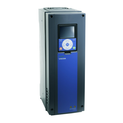
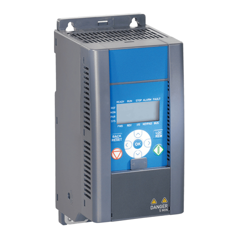
Vacon 100X series User manual

vacon 100x
vacon 100
ac drives
marine installation guide
®
®


PREFACE
Document ID: DPD01773A
Date: 25.1.2016
ABOUT THIS MANUAL
This manual is copyright of Vacon Ltd. All Rights Reserved. The manual is subject to change
without prior notice.
ABOUT THE PRODUCT
This manual describes the Vacon 100, Vacon 100 FLOW, and Vacon 100 X drives in a marine
environment, that is, in the marine and offshore industry. You can find all the other product-
related data in the Installation Manual of your Vacon 100 product.
The marine option gives the drive a better vibration resistance. For enclosed drives, there is
a handle on the cabinet door to hold on to, and a hook to keep the cabinet door open. The
enclosed drives also have a cabinet heater as default.
The Vacon 100 and Vacon 100 FLOW are available in enclosure sizes MR4-MR12, and their
enclosure class with the marine option is always IP54. The Vacon 100 X is available in
enclosure sizes MM4-MM6, and its enclosure class is always IP66. The drives can be used in
controlled electrical spaces in the special power distribution zone, the general power
distribution zone, and the passenger accommodation zone.
The product fulfills the most common marine certificates.
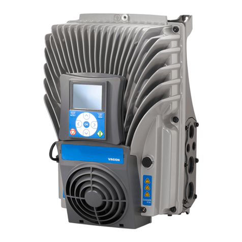
Fig. 1: A Vacon 100 enclosed drive, wall-mounted drive and a Vacon 100 X drive with the marine
option
PREFACE VACON · 3

VACON · 4
TEL. +358 (0)201 2121 · FAX +358 (0)201 212 205

TABLE OF CONTENTS
Preface
About this manual 3
About the product 3
1 Approvals 6
2 Safety 7
2.1 The safety symbols used in the manual 7
3 Receiving the delivery 8
3.1 Contents of the delivery 8
3.2 Removing the packaging and lifting the AC drive 8
3.2.1 Weight of the AC drive 8
3.2.2 Lifting the AC drive 9
4 Mounting 10
4.1 Dimensions of the AC drive with the marine option 10
4.1.1 Dimensions of the wall-mounted drives 10
4.1.2 Dimensions of the enclosed drives 15
4.2 Installation requirements 20
4.2.1 The maximum vibration 21
4.2.2 Installation safety in a marine environment 21
4.3 EMC requirements 21
4.3.1 Installing a drive in an IT network 22
4.3.2 Installing a drive in a grounded network: maximum 500 V, enclosure
sizes MM4-MM6 and MR4-MR9, not the enclosed drives 22
4.3.3 Installing a drive in a grounded network: 525-690 V, enclosure sizes
MR10-MR12, and the enclosed drives 23
4.4 Installation procedure 24
4.4.1 Installation of wall-mounted drives in a marine environment 24
4.4.2 Installation of enclosed drives in a marine environment 25
5 Commissioning and additional instructions 28
5.1 Maintenance 28
TABLE OF CONTENTS VACON · 5

1 APPROVALS
These classification societies have granted a marine type approval for this Vacon product.
You can find the general approvals in the Installation Manual of your Vacon 100 product.
•ABS (the American Bureau of Shipping)
•BV (Bureau Veritas)
•DNV GL (Det Norske Veritas - Germanischer Lloyd)
•LR (Lloyd's Register)
•RINA (RINA SERVICES S.p.A.)
VACON · 6 APPROVALS
1 TEL. +358 (0)201 2121 · FAX +358 (0)201 212 205

2 SAFETY
2.1 THE SAFETY SYMBOLS USED IN THE MANUAL
This manual contains warnings and cautions, which are identified with safety symbols. The
warnings and cautions give important information on how to prevent injury and damage to
the equipment or your system.
Read the warnings and cautions carefully and obey their instructions.
Table 1: The safety symbols
The safety symbol Description
WARNING!
CAUTION!
HOT SURFACE!
See the complete list of warnings in the Installation Manual of your Vacon 100 product.
NOTE! You can download the English and French product manuals with applicable safety, warning and caution
information from http://drives.danfoss.com/knowledge-center/technical-documentation/.
REMARQUE Vous pouvez télécharger les versions anglaise et française des manuels produit contenant l'en-
semble des informations de sécurité, avertissements et mises en garde applicables sur le site http://
drives.danfoss.com/knowledge-center/technical-documentation/.
SAFETY VACON · 7

3 RECEIVING THE DELIVERY
3.1 CONTENTS OF THE DELIVERY
The contents of the delivery
•The AC drive and the options that you ordered
•An accessories bag
•The parts for the marine option
•Safety Instructions, and the manuals for the options that you ordered
•Installation Manual and Application Manual if you ordered them, or Quick Guide
•The Marine Installation Guide
3.2 REMOVING THE PACKAGING AND LIFTING THE AC DRIVE
3.2.1 WEIGHT OF THE AC DRIVE
Table 2: The weights of the wall-mounted drives with the marine option
Enclosure size Weight [kg] Weight [lb.]
Wall-mounted drive, MR4 6.1 13.4
Wall-mounted drive, MR5 10.1 22.3
Wall-mounted drive, MR6 20.1 44.3
Wall-mounted drive, MR7 37.6 82.9
Wall-mounted drive, MR8 76.2 168.0
Wall-mounted drive, MR9 134.6 296.7
Table 3: The weights of the enclosed drives with the marine option
Enclosure size Weight [kg] Weight [lb.] Weight with the
common mode
and du/dt filters
[kg]
Weight with the
common mode
and du/dt filters
[lb.]
Enclosed drive, MR8 224 494 254 560
Enclosed drive, MR9 296 653 336 741
Enclosed drive, MR10 446 983 486 1071
Enclosed drive, MR12 2 x 446 2 x 983 2 x 486 2 x 1071
VACON · 8 RECEIVING THE DELIVERY
3 TEL. +358 (0)201 2121 · FAX +358 (0)201 212 205

3.2.2 LIFTING THE AC DRIVE
LIFTING THE ENCLOSED DRIVE
1 When you lift the enclosed drive to an upright
position, be careful not to damage the springs at
the bottom of the drive.
•When the drive tilts, the springs are squeezed.
To prevent damage to the springs, do not keep
the drive tilted for an unnecessary long time.
•When the springs are squeezed, they can
bounce suddenly and cause damage to the
equipment.
A
B
A. The lifting hole
B. The springs at the bottom
WARNING!
Be careful when you lift the enclosed drive to an upright position. If the springs are
squeezed for too long, they can become damaged. Also, the springs can bounce
suddenly and cause injury to the personnel and/or damage to the equipment.
RECEIVING THE DELIVERY VACON · 9

4 MOUNTING
4.1 DIMENSIONS OF THE AC DRIVE WITH THE MARINE OPTION
Other dimensions can be found in the Installation Manual of your Vacon 100 product.
For the dimensions of the Vacon 100 X product, see its Installation Manual.
4.1.1 DIMENSIONS OF THE WALL-MOUNTED DRIVES
4.1.1.1 Dimensions of the wall-mounted drive with the marine option, MR4
17 (0.67)
345 (13.58)
313 (12.32)
129 (5.08)
190 (7.48)
110 (4.3) 4 x Ø6
(0.24)
Fig. 2: Dimensions of the wall-mounted drive with the marine option, MR4, [mm (in)]
VACON · 10 MOUNTING
4 TEL. +358 (0)201 2121 · FAX +358 (0)201 212 205

4.1.1.2 Dimensions of the the wall-mounted drive with the marine option, MR5
17 (0.67)
441 (17.36)
406 (15.98)
144 (5.67)
214 (8.43)
115 (4.53) 4 x Ø6
(0.24)
Fig. 3: Dimensions of the wall-mounted drive with the marine option, MR5, [mm (in)]
MOUNTING VACON · 11

4.1.1.3 Dimensions of the the wall-mounted drive with the marine option, MR6
17 (0.67)
576 (22.68)
540 (21.26)
195 (7.68)
229 (9.06)
148 (5.83) 4 x Ø8
(0.31)
Fig. 4: Dimensions of the wall-mounted drive with the marine option, MR6, [mm (in)]
VACON · 12 MOUNTING
4 TEL. +358 (0)201 2121 · FAX +358 (0)201 212 205

4.1.1.4 Dimensions of the the wall-mounted drive with the marine option, MR7
17 (0.67)
680 (26.77)
645 (25.39)
237 (9.33)
259 (10.20)
190 (7.48) 4 x Ø8
(0.31)
Fig. 5: Dimensions of the wall-mounted drive with the marine option, MR7, [mm (in)]
MOUNTING VACON · 13

4.1.1.5 Dimensions of the wall-mounted drive with the marine option, MR8
39 (1.54)
1033 (40.67)
315 (12.40)
245 (9.65) 5
(0.20)
10
(0.39) 390 (15.35)
1111 (43.74)
4 x Ø11
(0.43)
Fig. 6: Dimensions of the wall-mounted drive with the marine option, MR8, [mm (in)]
VACON · 14 MOUNTING
4 TEL. +358 (0)201 2121 · FAX +358 (0)201 212 205

4.1.1.6 Dimensions of the wall-mounted drive with the marine option, MR9
1220 (48.03)
522 (20.55)
290 (11.42)
502 (19.76)
5
(0.20) 411 (16.18)
1298 (51.10)
10 x Ø12 (0.47)
Ø11
(0.43)
Fig. 7: Dimensions of the wall-mounted drive with the marine option, MR9, [mm (in)]
4.1.2 DIMENSIONS OF THE ENCLOSED DRIVES
Some options of the enclosed drives require additional cabinets. For more information, see
the Vacon 100 Enclosed Drives Installation Manual.
MOUNTING VACON · 15

4.1.2.1 Dimensions of the enclosed drive with the marine option, MR8
B86
(3.39)
B
B-B
A-A
13 (0.51)
383 (15.08)
4 x Ø12
(0.47)
2 x Ø13
(0.51)
335 (13.19)
548 (21.57)
936 (36.85)
2124 (83.62)
2170 (85.43)
13 (0.51)
672 (26.46) 0
-15 (0.59)
446 (17.56)
AA
781 (30.75) 0
-15 (0.59)
Fig. 8: Dimensions of the enclosed drive with the marine option, MR8, [mm (in)]
VACON · 16 MOUNTING
4 TEL. +358 (0)201 2121 · FAX +358 (0)201 212 205

4.1.2.2 Dimensions of the enclosed drive with the marine option, MR9
B86
(3.39)
B
A-A
535 (21.06)
646 (25.43)
548 (21.57)
936 (36.85)
2124 (83.62)
2170 (85.43)
672 (26.46) 0
-15 (0.59)
A A
781 (30.75) 0
-15 (0.59)
B-B
13 (0.51)
548 (21.57)
13 (0.51)
4 x Ø12
(0.47)
Fig. 9: Dimensions of the enclosed drive with the marine option, MR9, [mm (in)]
MOUNTING VACON · 17

4.1.2.3 Dimensions of the enclosed drive with the marine option, MR10
B86
(3.39)
B
B-B
548 (21.57)
A-A
535 (21.06)
646 (25.43)
548 (21.57)
936 (36.85)
2124 (83.62)
2170 (85.43)
13 (0.51)
672 (26.46) 0
-15 (0.59)
AA
781 (30.75) 0
-15 (0.59)
4 x Ø12
(0.47)
13 (0.51)
Fig. 10: Dimensions of the enclosed drive with the marine option, MR10, [mm (in)]
VACON · 18 MOUNTING
4 TEL. +358 (0)201 2121 · FAX +358 (0)201 212 205

4.1.2.4 Dimensions of the enclosed drive with the marine option, MR12
B86 (3.39)
B
A-A
B-B
1148 (45.20)
548 (21.57) 548 (21.57)
1246 (49.06)
548 (21.57)
2124 (83.62)
2170 (85.43)
672 (26.46) 0
-15 (0.59)
A A
781 (30.75) 0
-15 (0.59)
13 (0.51)
13 (0.51)
4 x Ø12
(0.47)
1135 (44.69)
Fig. 11: Dimensions of the enclosed drive with the marine option, MR12, [mm (in)]
MOUNTING VACON · 19

4.2 INSTALLATION REQUIREMENTS
In the marine environment, the power distribution system is normally divided into 3 zones.
The Vacon 100 drives are type-approved in these zones.
•Special power distribution zone
•General power distribution zone
•Passenger accommodation zone
The Vacon 100 drives are not type-approved in bridge or deck zones.
A
B
DE
EF
G
H
C
I
230 V
230 V
115 V
230 V
450 V
G
3~
M
3~
M
3~
G
3~
M
3~
Fig. 12: The installation zones in a marine environment
A. Special power distribution zone
B. Propulsion systems, bow thruster, etc.
C. Transformer or other way of decoupling
D. General power distribution zone
E. Normal consumers
F. Transformer or other way of decoupling
G. Passenger accommodation zone
H. Bridge and deck zone
I. Radiocommunication and navigation,
intercommunication, etc.
VACON · 20 MOUNTING
4 TEL. +358 (0)201 2121 · FAX +358 (0)201 212 205
Other manuals for 100X series
7
This manual suits for next models
1
Table of contents
Other Vacon Controllers manuals

Vacon
Vacon NX Active Front End User manual

Vacon
Vacon NX User manual

Vacon
Vacon X5 User manual

Vacon
Vacon 20 x User manual

Vacon
Vacon 100 INDUSTRIAL Instructions for use

Vacon
Vacon 10 User manual

Vacon
Vacon 20 User manual

Vacon
Vacon 20 SERIES Instructions for use

Vacon
Vacon 100 INDUSTRIAL User manual
Vacon
Vacon 100X series Instructions for use