Connections
This section covers:
nSelecting the location for the camera
nCabling notes
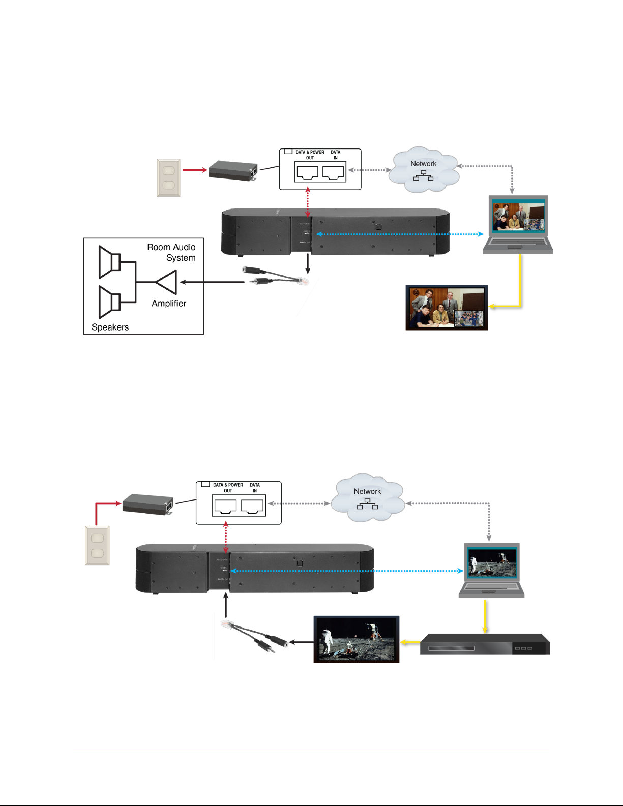
nConnection diagrams
And a required safety note here:
Note
PoE type networks connected to this equipment are for intra-building use only and should not be connected
to lines that run outside of the building in which this product is located.
Don’t Void Your Warranty!
Caution
This product is for indoor use. Do not install it outdoors or in a humid environment without the appropriate
protective enclosure. Do not allow it to come into contact with any liquid.
Do not install or operate this product if it has been dropped, damaged, or exposed to liquids. If any of these
things happen, return it to Vaddio for safety and functional testing.
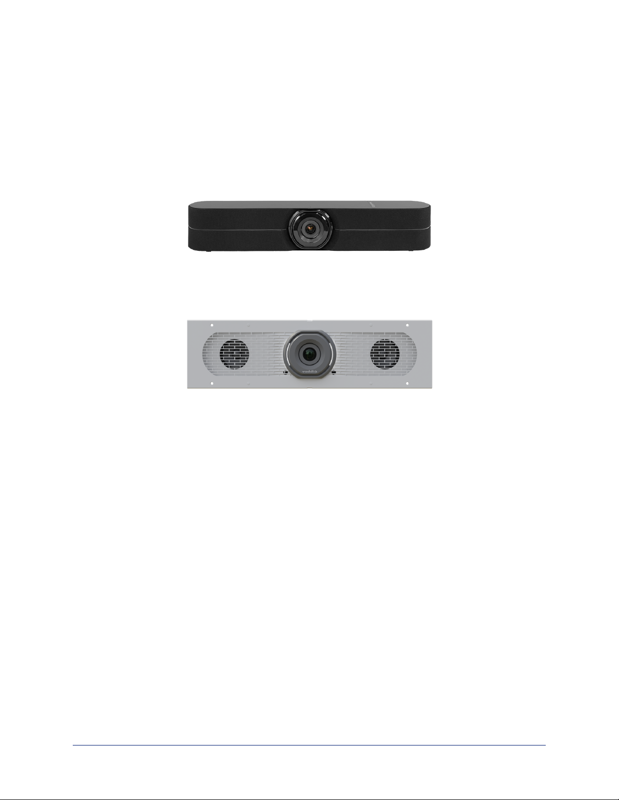
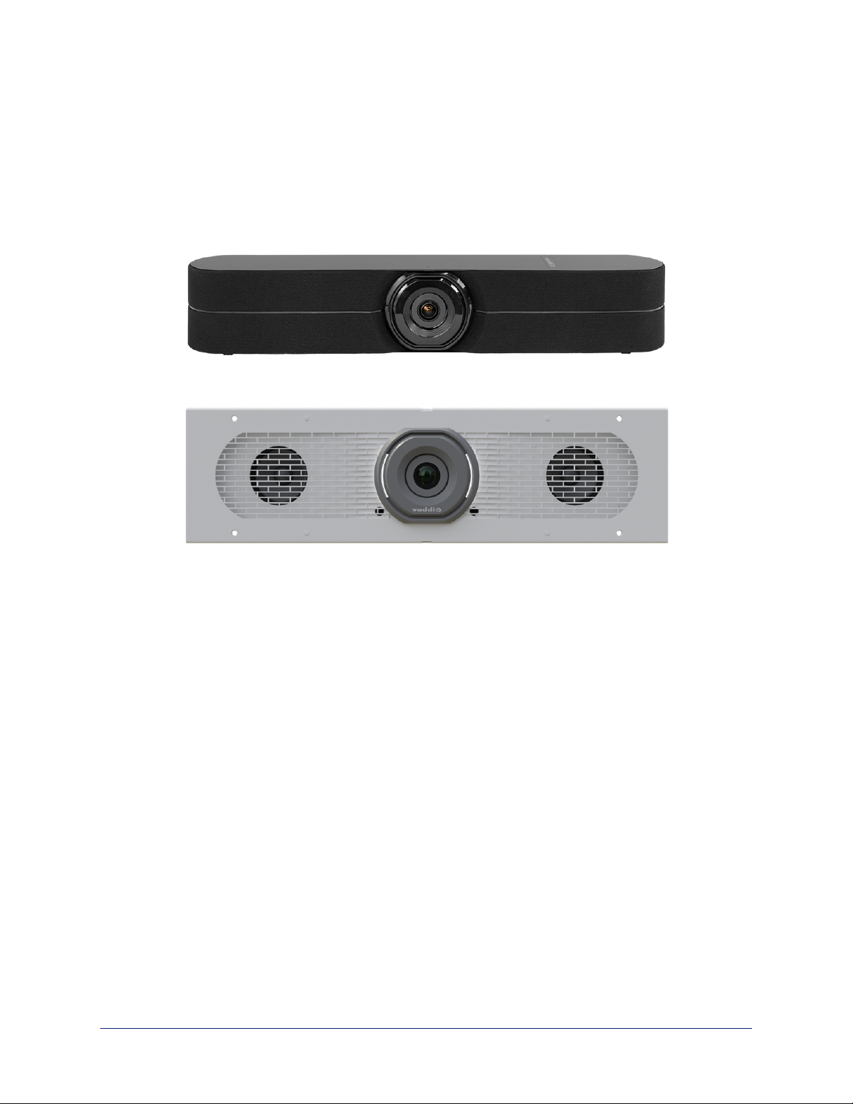
Before You Install the Camera
Keep these things in mind when deciding where to place the camera.
nConsider camera viewing angles, lighting conditions, line-of-sight obstructions, and in-wall obstructions
where the camera is to be mounted.
nEnsure that the camera will point away from light sources. The camera will not perform well if it is
pointed toward a light fixture or window.
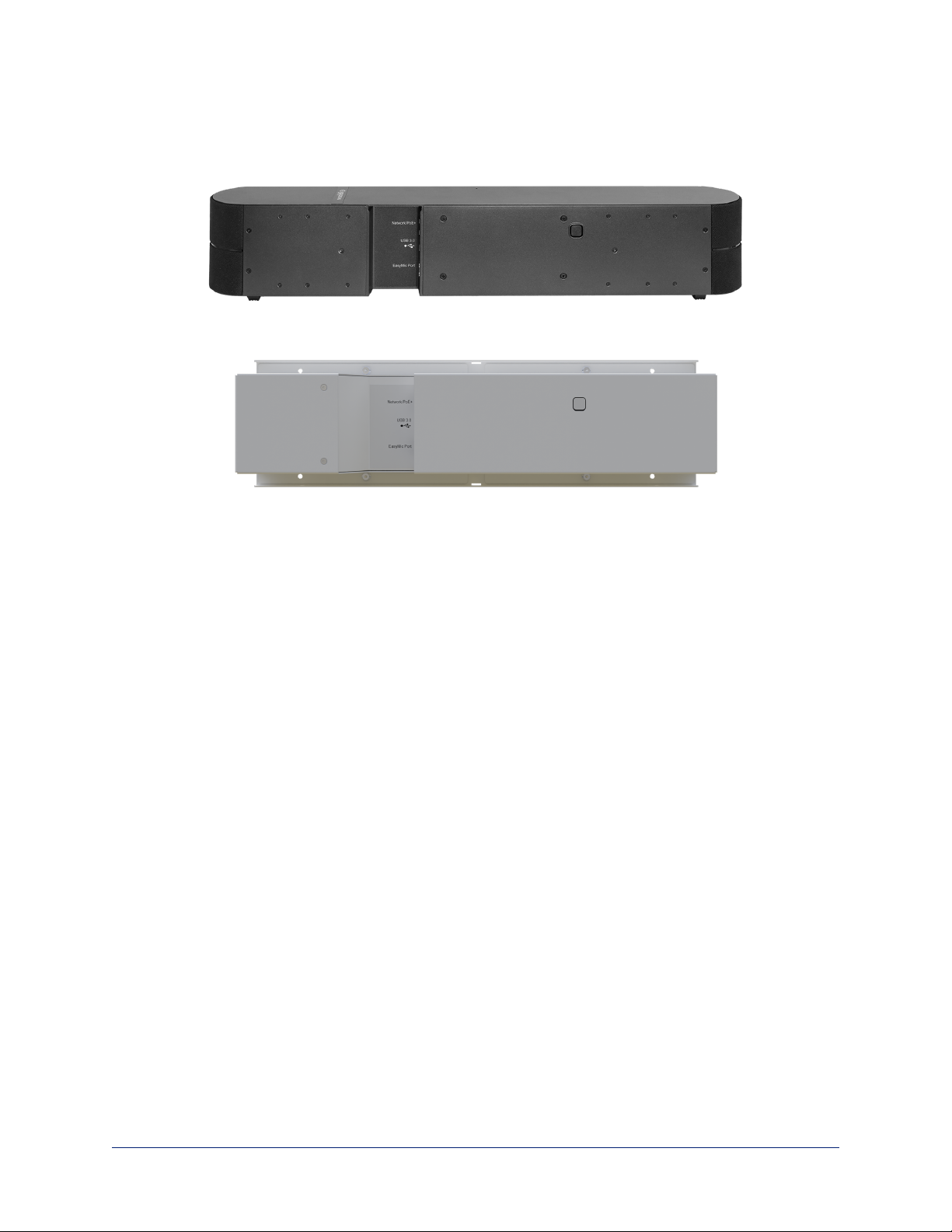
Prepare for a successful installation:
nBe sure you can identify all cables correctly.
nIf you make cables for this installation, check them for continuity.
nTalk to the network administrator. If installing the camera in a non-DHCP network (one that does not
automatically assign IP addresses), you will need to configure the camera with a static IP address as
directed by the network administrator.
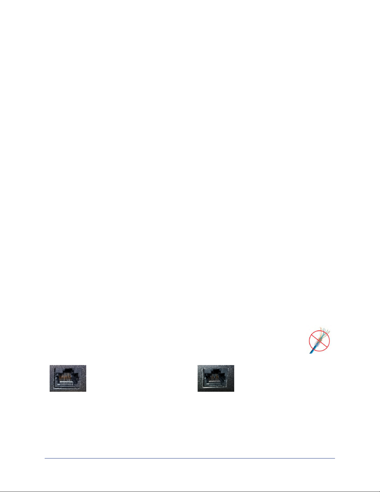
Cabling Notes
Caution
Do not use pass-through RJ-45 connectors when making cables for this product. Poorly
crimped connectors of this type can cause intermittent connections and degraded signal
quality. They can also damage the connectors on the product, which will void your warranty.
Intact – will make reliable contact
with cable connector
Damaged – Bent contact fingers
will NOT make reliable contact
with cable connector
4
Complete Manual for the HuddleSHOT All-in-One Conferencing Camera