Vaillant 06-5084 User manual

Montageanleitung
Umbausatz Sekundärwärmetauscher
(Ersatzteil-Nr.: 06-5084)
Assembly Instructions
Secondary heat exchanger conversion set
(Replacement part no.: 06-5084)
Instructions de montage
Jeu de transformation:
échangeur de chaleur secondaire
(Pièce de rechange n°: 06-5084)
Istruzioni per il montaggio
Set di sostituzione scambiatore di calore secondario
(Pezzo di ricambio n.: 06-5084)
Instrucciones de montaje
Juego de modificación intercambiador
de calor secundario
(Nº de repuesto: 06-5084)
Montagehandleiding
ombouwset secundaire warmtewisselaar
(vervangingsonderdeelnr.: 06-5084)

2

3
Inhalt Seite
4 - 11
12 - 19
20 - 27
28 - 35
36 - 43
44 - 51
Deutsch English Français Italiano Español Nederlands

4
Die Montage darf nur von einem anerkannten Fachmann
unter Beachtung der geltenden Vorschriften, Regeln und
Richtlinien durchgeführt werden!
Lieferumfang
Der Lieferumfang des Sets enthält:
- Anschlußstück (1)
- Sekundärwärmetauscher (2)
- Rohrleitungen (3, 4, und 5)
- Dichtungen (6)
- Ventilteller (7), nur erforderlich bei Umbau ab Seite 9.
23 4 51
6
7

Deutsch
5
Montage des Sekundärwärmetauschers
Gehen Sie bei der Montage bitte wie folgt vor:
●Trennen Sie das Gerät vom Stromnetz, schalten Sie das Gerät
aus und warten Sie bis das Wasser der Anlage abgekühlt ist.
●Öffnen Sie das Gerät und nehmen Sie die linke Seitenwand des
Gerätes ab.
●Entleeren Sie das Gerät heizungsseitig.
●Sperren Sie die Kaltwasserzufuhr ab, öffnen Sie eine Warmwas-
serzapfstelle und entleeren Sie die Brauchwasserleitungen.
●Demontieren Sie den alten Sekundärwärmetauscher des
Gerätes.
☞Fangen Sie das Restwasser in einem geeigneten Gefäß auf.
☞Die Rohrleitungen müssen im Gerät verbleiben. Sie sind für den
Anschlußdes neuen Sekundärwärmetauschers vorgesehen.
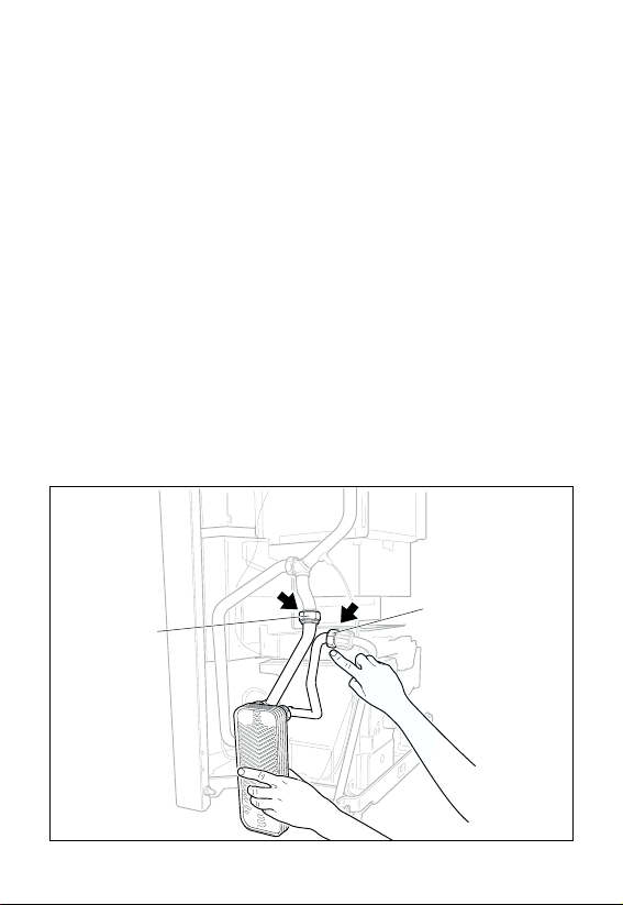
●Schrauben Sie die Rohrleitungen (3 und 4) und das Anschluß-
stück (1) in der gezeigten Position handfest an den neuen
Sekundärwärmetauscher (2).
Verwenden Sie die neuen Dichtungen!
1
3
2
4

6
●Montieren Sie den Sekundärwärmetauscher mit den Rohrleitun-
gen (3 und 4) wie gezeigt in das Gerät.
Verwenden Sie die neuen Dichtungen!
☞Ziehen Sie die Verschraubungen zunächst nur locker an, um den
Sekundärwärmetauscher noch ausrichten zu können.
●Montieren Sie den Anschluß (1) und das Rohr (5) mit den zuge-
hörigen Rohrleitungen.
Verwenden Sie die neuen Dichtungen!
●Ziehen Sie jetzt alle Anschlüsse fest.
4
3

Deutsch
7
Für Geräte, die in Gebieten mit besonders kalkhaltigem
Wasser installiert werden, empfiehlt Vaillant Sondermaß-
nahmen zu beachten:
Vaillant empfiehlt zur Vermeidung von Verkalkung folgende
Maßnahmen durchzuführen:
●
Durchtrennen der Brücke W 18 auf der Leiterplatte Nr. 25 29 60
●Einsetzen eines neuen Ventiltellers
5
1

8
Entfernen der Brücke W 18
Die Brücke W 18 muß nur bei Geräten mit einer Hybrid-Leiterplatte
Nr. 25 29 60 durchtrennt werden. Sie erkennen diese Geräte an
der Außenkontur des Schaltkastens (siehe untenstehende
Abbildung).
●Stellen Sie sicher, daß das Gerät vom Stromnetz getrennt ist.
●Lösen Sie die Schrauben (1) und ziehen Sie den Schaltkasten
nach vorn.
●Nehmen Sie die mittlere Leiterplatte (2, Nr. 25 29 60) heraus.
●Durchtrennen Sie die Brücke W 18 (3) auf der mittleren
Leiterplatte.
●Montieren Sie die mittlere Leiterplatte und den Schaltkasten.
☞Das Durchtrennen der Brücke W 18 reduziert die maximale
Vorlauftemperatur im Warmwasserbetrieb auf ca. 70 °C.
1
25 29 60
2
3
W 18
W 18

Deutsch
9
Wechsel des Ventiltellers im Vorrangumschaltventil
Beim Wechsel des Ventiltellers gehen Sie bitte wie folgt vor:
●Bauen Sie das Vorrangumschaltventil aus.
●Entfernen Sie die drei Schrauben (1) und nehmen Sie das
Ventilgehäuse (2) ab.
●Ersetzen Sie den alten Ventilteller (3) durch den im Lieferumfang
enthaltenen Ventilteller (4).
●Setzen Sie das Ventilgehäuse wieder zusammen.
Verwenden Sie eine neue Dichtung!
●Bauen Sie das Vorrangumschaltventil wieder in das Gerät ein.
1
32
4

10
Gerät auffüllen und in Betrieb nehmen
●Öffnen Sie eine Warmwasserzapfstelle.
●Öffnen Sie die Kaltwasserzufuhr und schließen Sie die
Warmwasserzapfstelle, wenn die Rohre frei von Luft sind.
●Öffnen Sie die Wartungshähne und füllen Sie das Gerät mit
Wasser auf.
●Heben Sie die Stromnetztrennung wieder auf und schalten Sie
das Gerät ein.
●Überprüfen Sie die Rohrleitungen auf Dichtheit.
●Montieren Sie die linke Seitenwand.
●Schließen Sie das Gerät.

Deutsch
11
I
0

12
Assembly may only be done by a trained technician in
accordance with the applicable rules, guidelines and
regulations!
Scope of delivery
The scope of delivery of the set includes the following:
- Connection (1)
- Secondary heat exchanger (2)
- Pipes (3, 4, and 5)
- Seals (6)
- Valve disk (7, not necessary in GB)
23 4 51
6
7

13
English
Assembling the secondary heat exchanger
Proceed as follows to assemble the secondary heat exchanger:
●Unplug the unit from its electrical supply, switch off the unit and
wait until the water in the unit has cooled down.
●Open the unit and remove the left side panel of the unit.
●Drain the heating side of the unit.
●Shut off the cold water supply, open a warm water tap and
drain the used water pipes.
●Remove the old secondary heat exchanger from the unit.
☞Collect the remaining water in an appropriate container.
☞The pipes are to remain in the unit. They are to be used for
connecting the new secondary heat exchanger.
●Screw the pipes (3 and 4) and the connection (1) onto the new
secondary heat exchanger (2) to the position shown until hand-
tight.
Use the new seals!
1
3
2
4

14
●Mount the secondary heat exchanger with the pipes (3 and 4)
on the unit as shown.
Use the new seals!
☞Screw the threaded pipe connectors together loosely at first so
that you will still be able to adjust the position of the secondary
heat exchanger.
●Screw the connection (1) and pipe (5) to the corresponding
pipes.
Use the new seals!
●Now tighten all connections.
4
3

15
English
Special precautions must be taken when the unit is
installed in any region where the water contains high
levels of lime!
Vaillant recommends you to take the following precautions in
addition to exchanging the secondary heat exchanger for water
containing high levels of lime:
●Cut jumper W 18 on circuit board no. 25 29 60
5
1

16
Removing jumper W 18
Jumper W 18 only needs to be cut on units with hybrid circuit
board no. 25 29 60. You can determine if your unit contains this
circuit board by the outer contour of the switch box (see the figure
below).
●Make sure that the unit has been unplugged from the electrical
supply.
●Remove the screws (1) and pull the switch box forward.
●Remove the middle circuit board (2, no. 25 29 60).
●Cut through jumper W 18 (3) on the middle circuit board.
●Reinsert the middle circuit board and the switch box.
☞Cutting jumper W 18 reduces the maximum supply temperature
when in warm water mode to about 70 °C.
1
25 29 60
2
3
W 18
W 18

17
English

18
Filling the unit and putting it into operation
●Open a warm water tap.
●Open the cold water supply and close the warm water tap when
all air has been let out of the pipes.
●Open the maintenance taps and fill the unit with water.
●Reconnect the unit to the electrical supply and switch the unit on.
●Check the pipes for leaks.
●Place the left side panel back on the unit.
●Close the unit.

19
English
I
0

20
Le montage ne doit être réaliséque par un technicien
reconnu respectant les prescriptions, réglementations et
directives en vigueur.
Volume de livraison
L’ensemble comprend les éléments suivants:
- Raccord (1)
- Echangeur de chaleur secondaire (2)
- Canalisations tubulaires (3, 4, et 5)
- Joints d’étanchéité (6)
- Tête de soupape (7, ce n´est pas nécessaire in France)
23 4 51
6
7
Table of contents
Languages:
Other Vaillant Industrial Equipment manuals