User's Guide ______________________________________________________________________
2 ________________________________________________________________ M210701EN-A
Fixed Probe Model ..............................................................22
Remote Probe Model ..........................................................22
Calibration and Adjustment...................................................23
Relative Humidity Adjustment Using the Push-Buttons ......24
Adjustment with HM70 ........................................................25
Field Checking and Adjustment Using a Calibrated
Reference Probe ............................................................26
One-Point Adjustment Using a Calibrator ......................26
Two-Point Adjustment Using a Calibrator ......................27
LiCl-NaCl Adjustment .....................................................28
Adjustment with HMI41 .......................................................29
Connections and Selecting the Calibrator Function.......30
Offset and Gain Adjustments .........................................31
HMI41 as a Reference Meter ....................................31
HMI41 as a Terminal.................................................32
Troubleshooting..............................................................34
Analog Output Tests ..............................................................35
CHAPTER 5
TROUBLESHOOTING..................................................................................37
Error Mode...............................................................................37
Technical Support ..................................................................37
Return Instructions ................................................................37
Vaisala Service Centers.........................................................39
CHAPTER 6
TECHNICAL DATA ......................................................................................41
Specifications .........................................................................41
Dimensions in mm (inches)...................................................45
List of Figures
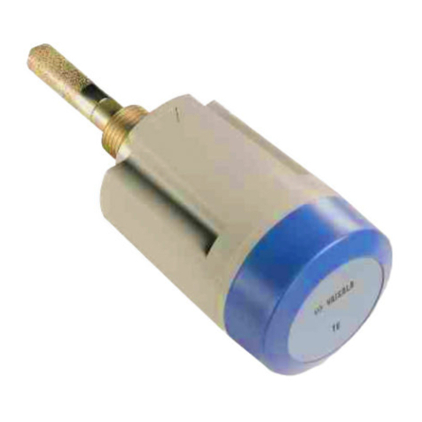
Figure 1 Fixed Probe Model ...................................................................11
Figure 2 Remote Probe Model................................................................11
Figure 3 Plastic Wall Assembly Plate .....................................................13
Figure 4 Plastic Wall Assembly Plate with Aluminium Installation Plate 14
Figure 5 HMT100 Installation with Rain Shield.......................................15
Figure 6 Installation of the Humidity Probe with the Radiation Shield....16
Figure 7 Probe Installation with the Duct Installation Kit ........................17
Figure 8 Assembly of the Humidity Probe with the Duct Installation Kit.18
Figure 9 Drilling Instructions ...................................................................18
Figure 10 HMT100 Connection Board ......................................................19
Figure 11 cIsolated Current-Loop Wiring, dVoltage Output Wiring......20
Figure 12 Removing the Humidity Probe (Fixed Probe Model)................22
Figure 13 Removing the Humidity Probe (Remote Probe Model) ............23
Figure 14 Adjustment Buttons ..................................................................24
Figure 15 Location of the MI70 Probe and Cable Connector Ports..........25
Figure 16 Example of the MI70 Adjustment Menu ...................................27
Figure 17 Example of the MI70 Adjustment Mode Graph Display ...........27
Figure 18 Location of the HMI41 Calibration Connector ..........................29
Figure 19 Accuracy of Temperature Measurement ..................................42
