manuals.online logo
Brands
  1. Home
  2. •
  3. Brands
  4. •
  5. Vaisala
  6. •
  7. Transmitter
  8. •
  9. Vaisala PDT101 User manual

Vaisala PDT101 User manual

Other Vaisala Transmitter manuals

Vaisala HMDW60 User manual

Vaisala

Vaisala HMDW60 User manual

Vaisala Drycap DMT152 User manual

Vaisala

Vaisala Drycap DMT152 User manual

Vaisala DRYCAP DMT143 User manual

Vaisala

Vaisala DRYCAP DMT143 User manual

Vaisala INTERCAP HMDW80 SERIES User manual

Vaisala

Vaisala INTERCAP HMDW80 SERIES User manual

Vaisala Indigo300 User manual

Vaisala

Vaisala Indigo300 User manual

Vaisala HUMICAP HMW90 SERIES User manual

Vaisala

Vaisala HUMICAP HMW90 SERIES User manual

Vaisala CARBOCAP GMW80 Series User manual

Vaisala

Vaisala CARBOCAP GMW80 Series User manual

Vaisala INTERCAP HMW82 User manual

Vaisala

Vaisala INTERCAP HMW82 User manual

Vaisala HUMICAP HMT330 SERIES User manual

Vaisala

Vaisala HUMICAP HMT330 SERIES User manual

Vaisala HMP243 User manual

Vaisala

Vaisala HMP243 User manual

Vaisala CARBOCAP GMT220 SERIES User manual

Vaisala

Vaisala CARBOCAP GMT220 SERIES User manual

Vaisala HUMICAP HMT130 User manual

Vaisala

Vaisala HUMICAP HMT130 User manual

Vaisala HUMICAP HMW90 SERIES User manual

Vaisala

Vaisala HUMICAP HMW90 SERIES User manual

Vaisala HMD60 Series User manual

Vaisala

Vaisala HMD60 Series User manual

Vaisala HUMICAP HMT100 User manual

Vaisala

Vaisala HUMICAP HMT100 User manual

Vaisala HUMICAP HMT360 SERIES User manual

Vaisala

Vaisala HUMICAP HMT360 SERIES User manual

Vaisala TMI110 User manual

Vaisala

Vaisala TMI110 User manual

Vaisala DRYCAP DMT340 SERIES User manual

Vaisala

Vaisala DRYCAP DMT340 SERIES User manual

Vaisala Indigo500 Series User manual

Vaisala

Vaisala Indigo500 Series User manual

Vaisala HMD62 User manual

Vaisala

Vaisala HMD62 User manual

Vaisala Humicap HMD60Y User manual

Vaisala

Vaisala Humicap HMD60Y User manual

Vaisala DPT146 User manual

Vaisala

Vaisala DPT146 User manual

Vaisala HUMICAP HMT360 SERIES User manual

Vaisala

Vaisala HUMICAP HMT360 SERIES User manual

Vaisala HMD60 Series User manual

Vaisala

Vaisala HMD60 Series User manual

Popular Transmitter manuals by other brands

Seneca K120RTD installation manual

Seneca

Seneca K120RTD installation manual

Nautel GV40 installation manual

Nautel

Nautel GV40 installation manual

HumanTechnik cm-light operating instructions

HumanTechnik

HumanTechnik cm-light operating instructions

INOR APAQ C130 TC User instructions

INOR

INOR APAQ C130 TC User instructions

Linear DXS-64 operating instructions

Linear

Linear DXS-64 operating instructions

FeinTech ABT00102 instruction manual

FeinTech

FeinTech ABT00102 instruction manual

Geo Web Pack quick start guide

Geo

Geo Web Pack quick start guide

Inovonics EchoStream EN1210W installation instructions

Inovonics

Inovonics EchoStream EN1210W installation instructions

IKONNIK KA-6 quick start guide

IKONNIK

IKONNIK KA-6 quick start guide

Rohde & Schwarz SR8000 Series System manual

Rohde & Schwarz

Rohde & Schwarz SR8000 Series System manual

Audio Technica UniPak ATW-T93 Installation and operation

Audio Technica

Audio Technica UniPak ATW-T93 Installation and operation

NIVELCO EasyTREK SCA-300 Series Programming manual

NIVELCO

NIVELCO EasyTREK SCA-300 Series Programming manual

Honeywell 5816WMBR installation instructions

Honeywell

Honeywell 5816WMBR installation instructions

Kamstrup READy MTU Installation and operation guide

Kamstrup

Kamstrup READy MTU Installation and operation guide

Omega ZW Series user guide

Omega

Omega ZW Series user guide

ABB Field 264H Instructions for installation

ABB

ABB Field 264H Instructions for installation

Dejero EnGo 3x manual

Dejero

Dejero EnGo 3x manual

Rosemount 4600 Reference manual

Rosemount

Rosemount 4600 Reference manual

manuals.online logo
manuals.online logoBrands
  • About & Mission
  • Contact us
  • Privacy Policy
  • Terms and Conditions

Copyright 2025 Manuals.Online. All Rights Reserved.

Vaisala Differential Pressure Transmitter
PDT101
M211284EN-E ___________________________________________________________________________________ 1
Die deutschsprachige Version kann von www.vaisala.com/PDT101
heruntergeladen werden.
Vous pouvez télécharger la version française sur www.vaisala.com/PDT101.
日本語版は www.vaisala.com/PDT101 からダウンロードできます。
您可以访问 www.vaisala.com/PDT101 下载简体中文翻译。
WARNING - READ BEFORE INSTALLATION
Vaisala Differential Pressure Transmitter PDT101 is a high-performance
instrument designed primarily for use in life science and cleanroom
applications. PDT101 is not authorized for use as a critical component in life
support devices or systems. Consult Vaisala before installing if there are any
questions or concerns.
Overpressure: Pressure spikes in excess of the rated overpressure capability
of the transmitter may cause irreversible electrical and/or mechanical damage
to the transmitter.
Static electrical charges: To avoid damage to the transmitter the
operator/installer should follow proper ESD (electrostatic discharge)
protection procedures.
TECHNICAL SPECIFICATION
Performance
Measurement range (bidirectional)
±60 Pa
or ±0.25 in H2O
Overpressure
Proof pressure
1.0 bar
Burst pressure
1.7 bar
Static pressure
1.7 bar
Pressure type
Differential, gauge,
vacuum and compound
Accuracy
(incl. non-linearity, hysteresis,
repeatability and zero/span
calibration settings)
0.4 % span
Long-term stability
≤0.5 % span/year
Response time (10...90 %)
250 ms
Warm-up time
15 s
Compensated temperature range
+2...+54 °C
(+35.6...+129.2 °F)
Temperature dependence
±(0.065 Pa + 0.054 % of reading) / °C
or
±(0.00015 inH2
O + 0.03 % of reading) / °F
(reference 21 °C or 70 °F)
Mounting position error
(zero adjustable)
≤1 %/g (calibration in vertical
position is standard)
Adjustments (front accessible)
Zero
±5 % span
Span
±3 % span
Operating environment
Operating temperature
-18...+70 °C (-0.4...+158 °F)
Storage temperature
-40...+82 °C (-40...+179.6 °F)
Electromagnetic compatibility
EN61326-1, Basic immunity
test requirements
Note: If used in an electromagnetic field of 3 V/m, with narrow frequency area
of 80 - 120 Mhz, it is possible that the current output of PDT101 can deviate
max. 0.8% (with accuracy specified 0.4%).
Inputs and outputs
Process connection
1/4" barbed fittings
Output signal
2-wire
4...20 mA
3-wire
0...5 VDC
(user selectable 0...10 VDC)
Operating voltage
2-wire output 4...20 mA
12...36 VDC
3-wire output 0...5 VDC
11.5...36 VDC
3-wire output 0...10 VDC
14...36 VDC
or 24 VAC
Max. loop resistance for 4...20 mA
≤(Supply voltage - 12V)/0.022 A
Supply current
max. 20 mA for 4...20 mA output signal
Optical process diagnostics
LED visual indicator
Electrical connection
Euro style pluggable terminal block accepts
12...26 AWG wire (0.13 up to 3.31 mm
2
)
Mechanics
Medium (measured gas)
Clean and dry air, non-conducting and
non-corrosive gases
Material
Process connection
Brass
Sensor element
Silicon, aluminum, glass
Case
NEMA type 1 fire-retardant ABS 1
(meets UL94-5VA)
Mounting
Threaded fastener for wall mounting
or DIN rail type EN50022
Housing classification
IP40
Weight
0.07 kg
MOUNTING
The transmitter can be mounted on an EN550022 rail or with M4 (#8) or
M5 (#10) screws using the mounting holes provided.
POWER
HI LO
SPAN
ZERO
ø5
ø4
37
48
74 84.6
9.4
33.6
Figure 1 Dimensions (in mm)
POWER
HI LO
S PAN
ZER O
Zero adjust
potentiometer
Span adjust
potentiometer
Power LED
Terminal block
Figure 2 PDT101 Transmitter
Quick Guide _______________________________________________________________________________ PDT101
© Vaisala 2014. All rights reserved. ___________________________________________________________________ 2
SETUP
The transmitters are calibrated at the factory in the vertical position. Mounting
in the horizontal position can cause a zero shift of as much as ±1 % of span.
Any minor zero offset can be minimized using the zero adjust potentiometer
located on the front, left side of the instrument. Use a 3⁄32˝ or 2.5 mm slotted
or phillips screwdriver to turn the potentiometer.
To apply true zero differential pressure, pneumatically connect the high and
low pressure connections together using the tubing provided with the
transmitter. The barbed connection accepts 1⁄4˝ O.D. 1⁄8˝ I.D. tubing. The
tubing should remain in place until the transmitter is to be connected to the
tubing of the building control system (BCS).
ELECTRICAL WIRING
1. Remove the terminal block on the front of the transmitter.
2. Follow the terminal block label markings on the PDT101 to identify the
terminals, and connect the wires.
3. Firmly reinstall the terminal block plug to its mating connector.
Current Output Wiring (Black Terminal Block)
The left, negative (-), and right, positive (+) terminals are used, ignore the
center terminal which is not used. Connect the power supply positive lead to
the PDT101 positive terminal, connect the negative power supply lead to the
negative terminal of the BCS 4...20 mA input. Last, connect the (-) negative
terminal on the PDT101 to the (+) positive BCS input.
Use of a shielded cable, with the shield grounded, is required. Do not connect
the shield to the transmitter.
+
––
+
–+
BCS
Power
Supply
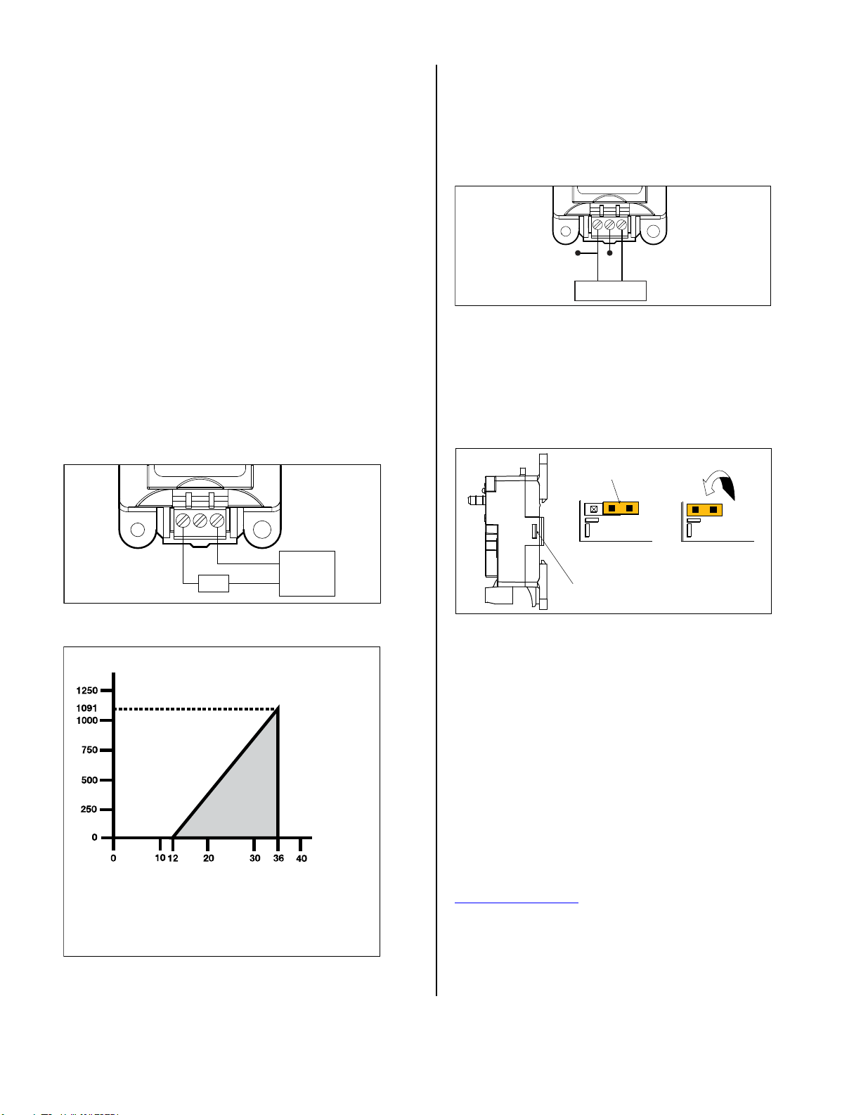
Figure 3 Current Output Wiring
Loop Resistance (Ω)
Supply
Voltage (V)
Vmin = 12V+ [.022A*(R L)]
*includes a 10% safety factor
RL = RS + RW
RL = Loop Resistance (ohms)
RS = Sense Resistance (ohms)
RW = Wire Resistance (ohms)
Loop Supply Voltage (Vdc)
OPERATING
REGION
Figure 4 Load Limitations
Voltage Output Wiring (Green Terminal Block)
The left terminal is the common (supply and output negative), the right
terminal is the Vin (supply positive). The middle terminal is the Vout (output
signal).
Use of a shielded cable, with the shield grounded, is required. Do not connect
the shield to the transmitter. Maximum cable length for voltage output wiring
is 30 m (98.4 ft).
+
–
Output signal
Common (V-) V
out Vin (V+, Supply)
Power Supply
Figure 5 Voltage Output Wiring
The PDT101 voltage output model is supplied as standard with 0...5 VDC
output. You can convert the unit to 0...10 VDC output by moving a jumper
inside the transmitter. Access the jumper by simultaneously pushing both
housing tabs away from the housing. Change jumper (orange) to the left as
shown below, and carefully reattach the housing cover. When finished, mark
the checkbox on front label indicating that the unit now provides a 0...10 VDC
output.
Jumper (orange)
Housing tabs (2 pcs)
0...5 Vdc 0...10 Vdc
Figure 6 Voltage Output Jumper
ROUTINE MAINTENANCE
To troubleshoot or verify performance, it is recommended to pneumatically
connect the pressure ports to each other and establish a zero offset reading in
the as-installed position. Adjusting zero will not affect span calibration.
Adjusting span should only be attempted when a high accuracy pressure
standard and high quality electrical meter are available.
REMOVAL FROM DIN RAIL
1. Unplug the wiring terminal block from the transmitter.
2. Insert a small slotted screwdriver into the black plastic clip extending
slightly below the transmitter case.
3. Raise the screwdriver handle up thereby forcing the spring clip down.
WARRANTY
For warranty information, visit our Internet pages at:
www.vaisala.com/warranty.
DISPOSAL
Dispose of the unit according to local regulations. Do not dispose of with
regular household waste. Recycle all applicable material.