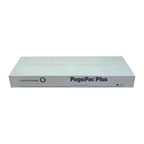
Valcom PagePac Plus V-5323100 User manual

ISSUE 2
1 947180
by
PagePac®
PAGEPAC PLUS CONTROLLER (V-5323100) AND
CONTROLLER WITH POWER SUPPLY (V-5323105)
INTRODUCTION
The PagePac® Plus System consists of the Controller,
AmpliCenter, and up to 3 Zone Expansion Units, providing up
to 56 paging and/or control zones. The self powered
Controller comes with its own power supply, enabling
it to control paging and control zones utilizing a paging amplifier
other than the AmpliCenter.
Dimensions/Weight
• 16.00”W x 1.80”H x 6.90”D
(40.64cm x 4.57cm x 17.53cm)
2.00 lbs. (0.91 kg)
SPECIFICATIONS
FEATURES
• 8 Zones Paging or Control • Night Bell
• Contact Closure Inputs or Outputs • 7 Alert Tones
• Loop Start, Ground Start C O Port, Analog Station • Page Zone Groups
or Dry Loop Access (page port with contact closure) • Flexible Numbering Plan
• Controller with Power Supply for Applications with
Distributed Amplified Speakers or Amplifiers other than PagePac
INSTALLATION
1. Mount the PagePac® Plus Controller and Zone Expansion Units, if any, to either a wall
(see Figure 1), cabinet or a rack (below the AmpliCenter or other amplifier) (see Figure 2).
Note: When installing the PagePac Plus Controller, leave at least four inches of space above and below
for proper ventilation.
Install the paging equipment in a ventilated room where there is easy access to speaker cabling (prefer-
ably in the telephone equipment room).

2
0dBm 0dBu N.B. AA
TO POW ER
AMP TO Z.E.U. TO AMP TELE MODE TO TEL
D.L. S.A. G.L. L.S.
SYSTEMSELECT
CONTROLLER
210-240 VAC
DRY LOOP 600 OHM
UNBALANCE OUTPUT
70V OUT
-
50-60 HZ
8.0 A
60 HZ
115 V
50 HZ
4.0 A
230 V
TO CONTROLLER
O DBM
OUT
OUTPUT
LOW FR EQ
UNIT
GROUND
+
GROUND START
DUCKING
MUSIC IN
LEFT
GROUND
C1
TIP
RING
PA G IN G IN
INPUT LEVEL
GROUND
RIGHT
PAGE ACCESSED
PAGE VOX
CAL
DRY LOOP HI Z
OVERLOAD
POWER
RING
GROUND
LOOP START
TIP
C1
PA G E IN
AMPLICENTER
105-120 VAC
D-SERIES
PREVIOUS
CONTROLLER
ZONE EXPANSION UNIT
FROM NEXT
CO NTR OLLER
TO
4"
4"
Figure 1. Wall Mounted Hardware
PagePac Plus
CONTROLLER
PagePac Plus
ZONE EXPANSION UNIT
PagePac Plus
D-SERIES AMPLICENTER
ALCOMV
Figure 2. Rack mounted Hardware
2.Connect background music input wires to Left and Right terminals if stereo or Left and Ground if not.
See Figure 3
Note: The optional audio source can be a CD or tape player, AM, FM, or commercial radio, or other audio
source.

3
If more than one AmpliCenter is used in the paging system, each one can be connected to the same music or
audio source, or different audio sources, if desired.
+
GROUND
GROUND
C1
RING
TIP
LEFT
GROUND
RIGHT
INPUT LEVEL
DUCKING
PAGE VOX
CAL
-
7 0 V O U T P A G IN G IN M U S IC IN
LOW FREQ
OUTPUT
+---
+
+
OR
MONO STEREO
3. Plug modular cord into connectors “To Amp” on Controller and “Page In” on AmpliCenter
(see Figure 4).
Note: If an amplifier other than the AmpliCenter is used, refer to page 10, Figure 16. There you will find
wiring diagrams and notes.
0dBm 0dBu N.B. AA
TO POWER
AMP TO Z.E.U. TO AMP TELE MODE TO TEL
D.L. S.A. G.L. L.S.
+
GROUND
GROUND
C1
RING
TIP
LEFT
GROUND
RIGHT
INPUT LEVEL
DUCKING
PAGE VOX
CAL
PAGE ACCESSED
UNBALANCE OUTPUT
OVERLOAD
POWER
DRY LOOP 600 OHM
DRY LOOP HI Z
GROUND START
LOOP START
-
70V OUT PAGING IN MUSIC IN PAGE IN
LOW FREQ
OUTPUT
O DBM
OUT
50-60 HZ
210-240 VAC
105-120 VAC
GROUND
RING
TIP
C1
TO CONTROLLER
UNIT
115 V
8.0 A
60 HZ
230 V
4.0 A
50 HZ
621534
652134
SYSTEMSELECT
AMPLICENTER
CONTROLLER
Figure 4. Page In Connection from Controller to AmpliCenter
4.Connect 8-pin Molex connector from AmpliCenter to Controller (see Figure 5).
Note: Connectors can only go in one way. DO NOT force in.
If you are using another type of amplifier, refer to page 10 Figure 16.

4
0dBm 0dBu N.B. AA
TO POW ER
AMP TO Z.E.U. TO AMP TELE MODE TO TEL
D.L. S.A. G.L. L.S.
+
GROUND
GROUND
C1
RING
TIP
LEFT
GROUND
RIGHT
INPUT LEVEL
DUCKING
PAGE VOX
CAL
PAGE ACCESSED
UNBALANCE OUTPUT
OVERLOAD
POWER
DRY LOOP 600 OHM
DRY LOOP HI Z
GROUND START
LOOP START
-
70V OUT PAGING IN MUSIC IN PAGE IN
LOW FR EQ
OUTPUT
O DBM
OUT
50-60 HZ
210-240 VAC
105-120 VAC
GROUND
RING
TIP
C1
TO CONTROLLER
UNIT
115 V
8.0 A
60 HZ
230 V
4.0 A
50 HZ
SYSTEMSELECT
AMPLICENTER
CONTROLLER
Figure 5. 8-pin Molex Connector from AmpliCenter to Controller
CAUTION
Damage to Controller will occur if the Molex connector (from AmpliCenter) is
pluggedInto the right connector (This goes from Controller to Zone Expansion Unit).
1 .Set the AmpliCenter Telephone Mode Selection Switch to Dry Loop 600 Ohms (Far left setting).
see Figure 6.
+
GROUND
GROUND
C1
RING
TIP
LEFT
GROUND
RIGHT
INPUT LEVEL
DUCKING
PAGE VOX
CAL
PAGE ACCESSED
UNBALANCE OUTPUT
OVERLOAD
POWER
DRY LOOP 600 OHM
DRY LOOP HI Z
GROUND START
LOOP START
-
70V OUT PAGING IN MUSIC IN PAGE IN
LOW FREQ
OUTPUT
O DBM
OUT
50-60 HZ
210-240 VAC
105-120 VAC
GROUND
RING
TIP
C1
TO CONTROLLER
UNIT
115 V
8.0 A
60 HZ
230 V
4.0 A
50 HZ
AMPLICENTER
Figure 6. AmpliCenter Mode Switch Setting
2. Connect 8-pin Molex from Controller to Zone Expansion Unit(s), if used. See Figure 7.
Note: Up to 3 Zone Expansion Units can be used, providing up to 56 paging and/or control zones.
0dBm 0dBu N.B. AA
TO PO W ER
AMP TO Z.E.U. TO AMP TELE MODE TO TEL
D.L. S.A. G.L. L.S.
SYSTEMSELECT
CONTROLLER
PREVIO US
CONTROLLER
ZONE EXPANSION UNIT
FROM NEXT
CONTROLLER
TO
POWER CONTROL 70V AUDIO
TO NEXT ZONE EXPANSION UNIT(S)
Figure 7. 8-pin Molex Connector from Controller to Zone Expansion Unit(s)
3. Set DIP switches on each Zone Expansion Unit, if any. See Figure 8.

5
Note: These DIP switches must be set correctly in order for the Controller to recognize the additional
zones.
PREVIOUS
CONTROLLER
FROM NEXT
CONTROLLER
TO
CONTROLLER
PREVIOUS
FROM
CONTROLLER
TO
NEXT
CONTROLLER
PREVIOUS
FROM NEXT
TO
CONTROLLER
ON 2nd ZONE EXPANSION UNIT SET DIP SW ITCH TO
ON 3rd ZONE EXPANSION UNIT SET DIP SW ITCH TO
ON
ON
ON
ENABLES
ZONES 9-24
ZONES 25-40
ENABLES
ENABLES
ZONES 41-56
12 43
1234
4321
Figure 8. Setting Zone Expansion Unit DIP Switches
4. Using a small standard screwdriver, make the following adjustments:
A. Adjust the Low Frequency Cut Off control to center position. This control cuts out the low frequency
bass so that horns and small speakers are not over-driven and distorted by excessive bass energy. Cut-
off frequency is continuously adjustable from 50Hz (full CCW rotation) to 400 Hz (full CW rotation). See
Figure 9.
B. Adjust Music Input level to the center position. Clockwise rotation will increase the level. Listen and
set to a comfortable level. (Make sure the music input is not too high check for the overload light on
amp).
C. Adjust Music Ducking level to the fully counterclockwise position. This feature allows music to
continue to be heard during a page, but at a reduced level. The range is less than –40dB (full CCW) to –
6dB (full CW). If music is not connected, set to full CCW.
D. Adjust the Page VOX (voiceactivated) sensitivity to the fully counterclockwise position.
E. Adjust page call to increase page volume or to lower page levels if overload light is on.
+
GROUND
GROUND
C1
RING
TIP
LEFT
GROUND
RIGHT
INPUT LEVEL
DUCKING
PAGE VOX
CAL
-
70V OUT PAGING IN MUSIC IN
LOW FREQ
OUTPUT
Figure 9. Sound Level Adjustments on AmpliCenter
5. Set Telephone Mode switch on Controller to match host telephone system interface port type.

6
See Figure 10.
0dBm 0dBu N.B. AA
TO POWER
AMP TO Z.E.U. TO AMP TELE MODE TO TEL
D.L. S.A. G.L. L.S.
SYSTEMSELECT
CONTROLLER
CO600
LSSA/DL GS DL=Dry Loop 600 ohms
SA/CO=Station Access/CO
GS=Ground Start Trunk Port
LS=Loop Start Trunk Port
Figure 10. Setting Controller Telephone Mode Switch
6. Connect cable from host telephone system to Controller Page Input. See Figure 11.
Note: Depending on the type of host telephone system interface port, the connection may differ slightly
from the illustration to the right. A direct 4-conductor cord from the Controller to the telephone system
can also be used, bypassing the connector block.

7
0dBm 0dBu N.B. AA
TO POWER
AMP TO Z.E.U. TO AMP TELE MODE TO TEL
D.L. S.A. G.L. L.S.
621534
SYSTEMSELECT
CONTROLLER
BLACK
GREEN
YELLOW
RED
2
16
5
34
CONNECT GREEN WIRE TO SYSTEM TIP T
CONNECT RED WIRE TO SYSTEM RING R
CONNECT BLACK WIRE TO THE DRY CONTACT CONTROL LEAD GROUND
CONNECT YELLOW WIRE TO THE DRY CONTACT CONTROL LEAD C1
TO HOST TELEPHONE
SYSTEM INTERFACE
PORT
TELEPHONE SYSTEM
CONNECTION TO HOST
Figure 11. Connecting Host Telephone System to Controller
7. Connect two wires from the night bell analog station port on the host telephone system to Controller night
bell (N.B.) input. See Figure 12. (Analog station port needs to provide 90 VAC ring voltage)
0dBm0dBuN.B.AA
TOPOWER
AMPTOZ. E.U.TOAMPTELE MODETOTEL
D.L. S.A. G.L. L.S.
SYSTEMSELECT
CONTROLLER
NIGHT BELL CONNECTI ON
FROMHOST TELEPHONE
SYSTEM ANALOGSTATI ON
PORT.
Figure 12. Night Bell Connection to Controller
8. Set the Zone Option switches on the Controller and Zone Expansion Units, if any.
Note: For each zone used, no matter what its function, this switch needs to be set to one of three set-
tings for proper zone operation.
The Controller has eight switches for zones 1-8. Each subsequent Zone Expansion Unit has switches for zones
9-24, 25-40, and 41-56.

8
Figure 13. Setting Zone Option Switches on Controller and Zone Expansion Units
CONNECTING SPEAKERS
Connect each speaker to the appropriate Home Run or Speaker-to-speaker wiring method as shown on the
floor plan. See Figure 14. (use shielded wire for 70 volt speaker wiring)
70V VOLT
AUDIO
OUTPUT
SPEAKER-TO-SPEAKER METHOD
HOME RUN METHOD
Figure 14. Speaker Wiring Methods

9
Figure 15. 70 volt Speaker and Contact Closure Zone Wiring to Controller
3. Test speaker wiring for short circuits.
Measure the resistance of each home run wiring with an ohmmeter. Any pair indicating a value of less than 15
Ohms must be rechecked for possible shorted wiring or speakers. Correct any problems and retest.
4. Make zone connections to Controller and any Zone Expansion Units. See Figure 15.
The zone connectors on the Controller and Zone Expansion Units can accommodate up to two 22 AWG wires or
four 24 AWG wires per zone output.
Note: DO NOT over tighten zone connector screws.
Check zone option switch setting with Zone Map and Zone Configuration Tables as you connect each zone (A
70V audio output setting going to other than speakers may damage other equipment).

10
POWERING UP SYSTEM
With all zones wired and connected to the Controller and Zone Expansion Units (if any), initial testing can begin.
Refer to Controls and Indicators, Terminals and Connector. Once initial testing is done, you can begin to
program the Controller with the features for each zone.
1.Plug the power cord into the AC input connector on the AmpliCenter. The following should happen:
A. The green Power LED on the AmpliCenter will turn on and stay on.
B. The green Page Access LED on the AmpliCenter also turns on, but will go out after a
few seconds.
C. On the Controller, verify that the green Phone System Enabled LED is off, and that the
yellow Attendant Access Enabled LED is off.
D. If background music is connected, adjust the Music In Input Level control on the
AmpliCenter(s) for an acceptable level.
NOTE: If an amplifier other than the AmpliCenter is used, make sure it is powered up and verify the
Controller LEDs.
2. Make an All Zone test page. Readjust sound levels by adjusting speaker tap settings, if
required.
A. Readjust Music Input level to the desired loudness relative to paging loudness.
B. Some loudspeaker taps may have to be re-adjusted to get even coverage at all
Locations. Be sure that the final speaker tap setting totals do not exceed the power
Rating of the Amplicenter.
3. Begin programming the Controller (refer to Programming Section).
locations.
SELF-POWERED CONTROLLER CONNECTIONS
The wiring diagrams in Figures 16 through 18 illustrate the connection of the Self-Powered Controller with other
amplifiers. In this way, most features associated with the Controller can be utilized with amplifiers other than the
AmpliCenter. Refer to Tables 1 and 2 for gain and sensitivity settings.
CONTROLLER WITH POWER SUPPLY TO GENERIC AMPLIFIER
To install the Controller to a Generic Amplifier (see Page 10, Figure 16):
1. Connect 0dBu or 0dBm output to amplifier audio input.
Note: Refer to Table 1 for controller audio output levels and volume control settings.
2. Connect Amplifier Audio Output (70.7V) to Amplified Audio Input on Controller.
3. Adjust Controller volume control (see Table 1).
4. If required, connect control input to amplifier from Controller zone set to “output contact closure program for
system HS (program 70).
5. Connect background music if needed to music input.
6. Connect host telephone system to Controller.
7. Plug power pack connector into Controller.
11
Figure 16. Connection of the Self-Powered Controller to Generic Amplifiers
Table 1. Controller Adjustable Output Level
Controller Volume Control Setting 600 Ohm Impedance Output Low Impedance Output
Full Counter Clockwise - 12dBm (195mVrms) - 6dBu (388mVrms)
Full Clockwise 0dBm (.775Vrms) + 6dBu (1.50Vrms)
Note: The generic amplifiers input must be dry, no battery or voltage can be present.

12
CONTROLLER WITH POWER SUPPLY TO AMPLIFIED SPEAKERS
To install a Controller to Amplified Speakers (see Figure 17):
1. Connect 0dBu output of Controller to Amplified Audio input of Controller.
2. Adjust Controller volume control to mid point.
3. Connect amplified speakers audio input to each zone connector.
4. Set zone option switches to Amplified Audio Output.
5. Connect host telephone system to Controller.
6. Plug Power Pack connector into Controller.

13

14
Figure 17. Self-Powered Controller Driving Amplified Speakers
CONTROLLER WITH POWER SUPPLY TO D-SERIES AMPLICENTER
To install a Controller to a D-Series AmpliCenter (see Figure 18):
1. Connect 6-conductor cord from Controller (To Amp) to AmpliCenter Page Input.
2. Connect 70V audio out from AmpliCenter to Amplified Audio, input of controller.
3. Connect host telephone system input to Controller.
4. Connect background music if needed to music input,of AmpliCenter.
5. Plug power pack connector into Controller.
15

16
0dBm0dBuN.B.AA
16. 5 VAC TOZ.E.U.TOAMP TELEMODESELECT TOTEL SYS
AMPLI FIED
AUDIO
G.L.S.A.D.L. L.S.
3
214356
16. 5 VAC
POWER
MODULE
TOHOST
TELEPHONE
SYSTEM
652134
216534
210-240 VAC
DRY LOOP 600 OHM
UNBALANCE OUTPUT
70VOUT
-
50-60 HZ
8.0 A
60 HZ
115 V
50 HZ
4. 0 A
230 V
TOCONTROLLER
ODBM
OUT
OUTPUT
LOWFREQ
UNIT
GROUND
+
GROUND START
DUCKING
MUSICIN
LEFT
GROUND
C1
TIP
RING
PAGINGIN
INPUT LEVEL
GROUND
RIGHT
PAGE ACCESSED
PAGE VOX
CAL
DRY LOOP HI Z
OVERLOAD
POWER
4312 56
RING
GROUND
LOOP START
TIP
C1
PAGEIN
AMPLI CENTER
105-120 VAC
SELF-POWERED
CONTROLLER
PAGEINTO
AMPLI FIER
AMPLI FIED
AUDIO
4
1
2
5
D-SERIES
Figure 18. Self-Powered Controller Connected to the PagePac D-Series AmpliCenter
PROGRAMMING THE CONTROLLER
The Controller is programmed to enable each zone to have different zone features, if required. There are two
ways to do the programming. One is via the RS-232 serial port on the Controller which is connected to an IBM
compatible (DOS) PC using the optional programming software.
An advantage of using a PC to configure the Controller is that screens can be viewed on the monitor to aid in
selecting the zones for various options. A re-programming of the entire system can be done before downloading
the configuration to the controller, saving down time. Furthermore, the old configuration can be saved and used
again.

17
The other method works via the telephone access port (like calling to make a page), which accepts only
touchtone telephone keypad inputs (DTMF) tones. The Controller has the ability to retain all programming
options in non-volatile EEPROM memory or as a .CFG (configuration) file on a personal computer.
PROGRAMMING STEPS
CAUTION
The Zone Option switches must be set before the system is powered up, and therefore before
programming the system.
The Zone Option switches on the rear of the Controller and Zone Expansion units must be set to match the zone
option selected for programming. The slide switch for each zone must be manually set to Contact Closure (to
switch on/off a device, such as a door security lock, remote amplifier, etc.), Input Contact Closure, or Audio
Output, depending on the mode selected for each zone.
IMPORTANT! It is recommended that the paging zone decisions be made and filled in on the Zone Map and
Configuration Tables, located on pages 25-29 prior to setting zone option switches and programming.
* * ENTER PROGRAMMING MODE
1. From any DTMF telephone in the system, dial the paging access extension.
2. Dial the Connect Password (if optioned).
You will hear the paging system dial tone.
3. Dial * *
Note: you will hear conformation tone. Now programming may begin.
1 0 RESET TO FACTORY DEFAULTS
1. Dial 1 0
You will hear two beeps from the Controller.
2. Dial 2 5 3 2 7
After a long pause, you will hear three beeps from the Controller. The controller is now set to factory default
conditions.
3. Program the system options (refer to the following paragraphs).
You may exit the programming mode by dialing #.
2 0 DEFINE LENGTH OF ALIAS NUMBERS
This system option allows you to set the length (3 or 4 digits) of the ALIAS number field. The default is 2 digits. If
you wish to assign ALIAS numbers to the paging zones, you must set the length parameter. The ALIAS number
is the dialing extension for the zone. If no ALIAS numbers are used, the Physical Zone Code is the dialing
extension for a zone.
Note: This MUST be done before “Zone Map Option – Assigning ALIAS Numbers,” later in this section.
1. Dial 20 to select this option.
Hear a DOUBLE beep.
Press 3 or 4 to set length of ALIAS numbers (number of digits dialed to reach paging zone).
Hear TRIPLE beeps.
2. To verify the setting, dial 2 1 and repeat step 2 above.
2 2 SET SERIAL PORT BIT RATE
The speed (bit rate) of the controller's RS-232 serial port can be set to the rate of the computer monitor or visual
display. Default is 9600 bps. The bit rate may be changed at any time, but the Controller must be reset (power
off then on again) in order to take effect. (This is the only program change requiring the Controller to be reset).
1. Dial 2 2 to select this option
Hear a DOUBLE beep.
2. Dial a code to select the Serial Port Bit Rate

18
0to select 300 bps
1to select 1200 bps
2to select 2400 bps
3to select 4800 bps
4to select 9600 bps
5to select 14400 bps
6to select 19200 bps
Hear TRIPLE beeps.
3. To verify the status of this option, dial 2 3 and repeat step 2 above.
2 4 INHIBIT DIAL TONE DETECT
Supervision of the Station/Centrex Access mode is accomplished in 3 ways, by monitoring the loop current and
the audio signal (including dial tone), and a forced disconnect timer. This option (only applicable in the station
access mode) enables you to defeat the dial tone detect function in order to send a tone via the Telephone
Interface to the output.
1. Dial 2 4 to select this option.
Hear a DOUBLE beep.
2. Dial 0 to Enable, or 1to Inhibit.
Hear TRIPLE beeps.
3. To verify the condition (OFF/ON) of the Dial Tone Detect option, dial 2 5 and repeat step 2
above.
3 0 SET CONNECT PASSWORD
This feature will not become active until the first time you enter a password, via the programming mode. The
factory default is NO password. The Connect password operates as a security block into the paging system,
restricting paging access to authorized users.
Note: You may want to use a short Connect password (2 or 3 digits only) for ease of use.
1. Dial 3 0 to select this option.
Hear a DOUBLE beep.
2. Enter the Password you wish to use (up to 6 digits). If the password has fewer than 6 digits, enter the #to
terminate the string.
Note: For example, 123456 is a valid password entry. 123# is also a valid password entry, resulting in
the password 123.
If you already have entered a password and want to remove it (to have NO password), just enter the # alone.
Hear TRIPLE beeps.
To verify that the new Connect password has been established, dial 3 1 and repeat step 2 above.
3 2 SET PROGRAMMING PASSWORD
Establishing a Programming password will restrict access to the programming mode of the PagePac Plus
paging system. It is recommended that access to programming be restricted to the System Administrator,
Telecommunications Manager, or other selected users.
Note: Your Connect and Programming passwords should not be the same. If this feature is active and
the system has been accessed via the telephone interface, then after the first digit of your Programming
password is pressed, the dial tone will stop and will not be returned until the correct password is
entered or until the user hangs up and re-enters the system.
This feature will become active once any programming password has been entered via the programming mode.
You are not required to establish such a password. The factory set default programming password is * *.
1. Dial 3 2 to select this option. Hear a DOUBLE beep.
2. Enter the Password you wish to use (up to 6 digits). If the password has fewer than 6 digits,
enter the #to terminate the string.
NOTE: For example, 234567 is a valid password entry. 234# is also a valid password entry, resulting in
the password 234.

19
If you already have entered a password and now want to remove it (to have NO password), just enter the #
alone. Hear TRIPLE beeps.
3. To verify that the new Programming password has been established, dial 3 3 and repeat step
2 above.
Forgot the Password? If either or both the connect password and programming password are forgotten, it will
be necessary to call the Help line (refer to page ii) for instructions how to erase the two passwords and be able
to enter new ones.
4 0 TURN CONFIRMATION TONE ON/OFF
When the option is ON, a tone will be sent to the telephone interface after a zone has been selected and before
a page can be made. The default setting is ON.
1. Dial 4 0 to select this option. Hear a DOUBLE beep.
2. Dial 0 to turn OFF, or 1 to turn ON. Hear TRIPLE beeps.
3. To verify the Confirmation Tone condition (OFF or ON), dial 4 1 and repeat step 2 above.
4 2 TURN PRE-ANNOUNCEMENT TONE ON/OFF
This tone is very similar to the initial talk-back warning tone, in the sense that it is sent to a zone when the zone
is accessed. This tone will be sent out to both speakers in the zone selected and to the telephone interface.
After this tone is sent, you may begin your page message. Default is ON.
1. Dial 4 2 to select this option. Hear a DOUBLE beep.
2. Dial 0 to turn OFF, or 1 to turn ON. Hear TRIPLE beeps.
3. To verify the Pre- Announcement Tone condition (OFF or ON), dial 4 3 and repeat step 2 above.
4 4 SET TALKBACK WARNING TONE
This tone is intended to alert a person that their conversation is being monitored through the paging system
loudspeaker. If Talkback is optioned for YES, then the choices will be Initial only, Initial and 30 Second Repeat
or Off. The default setting for this parameter is Initial and 30 Second Repeat.
1. Dial 4 4 to select this option. Hear a DOUBLE beep.
2. Dial 0 to turn OFF, 1 to select INITIAL tone only, or 2to select Initial and 30 Second repeat.
Hear TRIPLE beeps.
3. To verify the condition of the Talkback Warning Tone, dial 4 5 and repeat step 2 above.
5 0 SET VOX DISCONNECT TIMING
The system will hang up on a page if no audio is detected for the programmed amount of time. The default time
is 30 seconds, but can be varied from 10 seconds to 60 seconds, in 10 second increments, or can be disabled
completely.
1. Dial 5 0 to select this option. Hear a DOUBLE beep.
2. Dial the code to select a duration for the VOX Disconnect Timing:
0to turn OFF
1to select 10 seconds 4to select 40 seconds
2to select 20 seconds 5to select 50 seconds
3to select 30 seconds 6to select 60 seconds
Hear TRIPLE beeps.
3. To verify the duration of the VOX Disconnect Timing, dial 5 1 and repeat step 2 above.
5 2 ENABLE COMPUTER MONITOR
This option selects a device to be connected to the Controller RS-232 port, a computer monitor for logging of all
paging activity or a visual message display. The default setting is Computer Monitor.
By selecting Computer Monitor (the default option), the system is enabled to monitor activity on Atten-
dant Access, Telephone Interface, and Night Bell inputs. This feature requires that a PC computer be
connected to the RS-232 port of the Controller. Whenever the input becomes active, ASCII characters
will be sent out the RS-232 port (DB9 pin connector) to the computer. The ASCII characters will be inter

20
cepted by a special software package in the computer that logs the time, date, input zone, type of activ-
ity, zone that was paged, and duration of the activity. All such input activity to the paging system can
then be viewed (and recorded) on the computer.
By selecting Display, the monitoring activity described above enables commands to be sent to a visual message
display where preprogrammed messages are displayed.
1. Dial 5 2 to select this option.
Hear a DOUBLE beep.
2. Dial the 0to select Computer Monitor, or 1 to select Visual Display
Hear TRIPLE beeps.
3. To verify the status of this option, dial 5 3 and repeat step 2 above.
If a Computer Monitor or visual message display has been connected and Controller software
loaded, you will need to select the types of paging inputs to be displayed or recorded. See
next programming option select “Input to Computer Monitor.”
5 4 SELECT INPUT TO COMPUTER MONITOR
This option turns ON or OFF the inputs of Attendant Access, Telephone Access, and Night Bell to be recorded
and displayed by the Computer Monitor if you have activated it in Program 5 2. Default is OFF for all three.
You will need to repeat this procedure 3 times in order to reset all three inputs.
1. Dial 5 4 to select this option.
Hear a DOUBLE beep.
2. Dial the code to select an option for one of the three inputs:
0to turn OFF the Attendant Access.
1to turn ON the Attendant Access.
2to turn OFF the Telephone Access.
3to turn ON the Telephone Access.
4to turn OFF the Night Bell.
5to turn ON the Night Bell.
Hear TRIPLE beeps.
3. To verify the status of this option, dial 5 5 and repeat step 2 above.
5 6 SET SUPERVISED TRUNK MODE
If the host telephone system does not have a supervised trunk option this feature does not apply.
Proceed to Program 5 8.
Note: Once the option has been configured, you should place the Controller Telephone Mode switch to
the Ground Start position. Connect the telephone interface to a Loop Start trunk on the host system
using a standard two-conductor (not four-conductor) RJ-11 cable.
The Supervised Trunk access mode provides both VOX Disconnect and Forced Disconnect timeouts. When the
Controller detects that the it has been off hook for two minutes, it opens the trunk circuit for one second, ending
the call. Also, if no voice activity is detected for the period specified by the VOX Disconnect programming option
Program 50(normally 30 seconds), or if the telephone is overridden by a higher priority activity (i.e., attendant
access), the call is disconnected.
Note: The Ground Start and Station Access modes are not available when the Controller is configured
for Supervised Trunk mode. Supervised Trunk mode must be turned off to re-enable these access
modes.
1. Dial 5 6 to select this option
Hear a DOUBLE beep.
2. Press 0 to turn OFF, or 1 to turn ON
Hear TRIPLE beeps.
3. To verify the condition (ON/OFF) of the Supervised Trunk mode, dial 5 7 and repeat step 2
above.
Other manuals for PagePac Plus V-5323100
1
This manual suits for next models
1
Table of contents
Other Valcom Controllers manuals

Valcom
Valcom V-2000A User manual

Valcom
Valcom Pagepac Plus V-5335621 User manual

Valcom
Valcom V-9932 User manual

Valcom
Valcom V-1092 User manual

Valcom
Valcom V-1092 User manual

Valcom
Valcom VL-9998RM User manual

Valcom
Valcom V-VCU User manual

Valcom
Valcom V-1092 User manual

Valcom
Valcom V-1092 User manual

Valcom
Valcom V-2000 User manual