Vanguard EZCT-2000B User manual

EZCT-2000BTM
DIGITAL CURRENT-TRANSFORMER TESTER
USER’S MANUAL
Vanguard Instruments Company, Inc.
1520 S. Hellman Ave.
Ontario, California 91761, USA
TEL: (909) 923-9390
FAX: (909) 923-9391
July 2009
Revision 1

EZCT-2000B USER’S MANUAL REV 1
i
SAFETY SUMMARY
FOLLOW EXACT OPERATING PROCEDURES
Any deviation from the procedures described in this User’s Manual may create one or more
safety hazards, may damage the EZCT-2000B, or cause errors in the test results. Vanguard
Instruments Company, Inc. assumes no liability for unsafe or improper use of the EZCT-2000B.
All safety precautions provided in this manual must be observed during all phases of testing
including test preparation, test lead connection, actual testing, and test lead disconnection.
SAFETY WARNINGS AND CAUTIONS
The EZCT-2000B can produce a voltage up to 2,000 Vac that can cause severe injury and/or
equipment damage. Due to this reason, the EZCT-2000B shall be used only by trained
operators.
The EZCT-2000B’s X output terminals are rated to 2,000 Vac working voltage. Any voltage above
2,000 Vac will damage the input circuitry. Please see section 3.2 for further information.
All devices under test shall be off-line and fully isolated. Never attempt to test any current
transformer still connected to a circuit. All current transformer terminals shall be isolated
before conducting any test with the EZCT-2000B.
Always ground the EZCT-2000B to a substation ground before connecting the test cables to a
transformer.
DO NOT MODIFY TEST EQUIPMENT
To avoid the risk of introducing additional or unknown hazards, do not install substitute parts or
perform any unauthorized modification to any EZCT-2000B test unit. To ensure that all designed
safety features are maintained, it is highly recommended that repairs be performed only by
Vanguard Instruments Company factory personnel or by an authorized repair service provider.
Unauthorized modifications can cause safety hazards and will void the manufacturer’s
warranty.
WARNING
Do not remove test leads during a test. Failure to heed this warning can result in electrical
shock to personnel and damage to the equipment.

REV 1 EZCT-2000B USER’S MANUAL
ii
TABLE OF CONTENTS
CONVENTIONS USED IN THIS DOCUMENT ..................................................................................... 1
1.0 INTRODUCTION.................................................................................................................... 2
1.1 General Description and Features ................................................................................... 2
1.2 Furnished Test Accessories.............................................................................................. 4
1.3 Technical Specifications ................................................................................................... 5
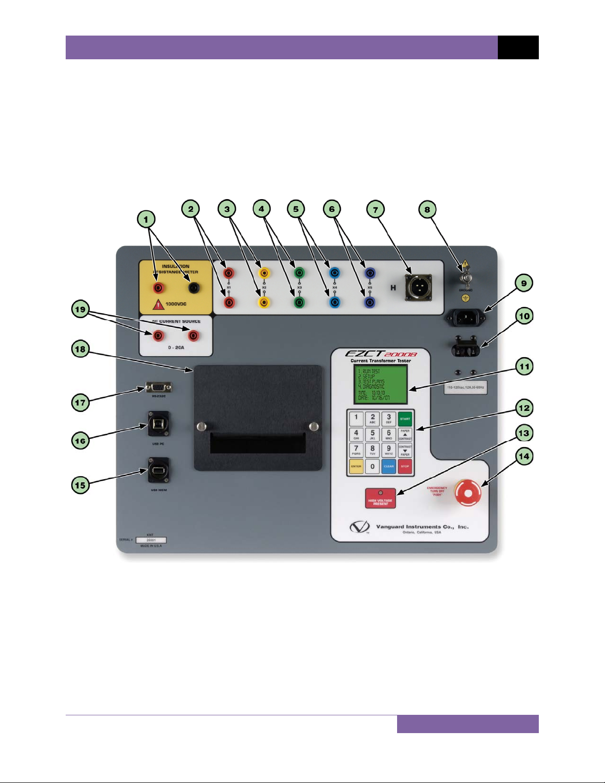
1.4 EZCT-2000B Controls and Indicators ............................................................................... 6
2.0 PRE-TEST SETUP ................................................................................................................... 8
2.1 Operating Voltages .......................................................................................................... 8
2.2 LCD Screen Contrast Control............................................................................................ 8
2.3 Printer Paper Control....................................................................................................... 8
2.4 Printer Paper.................................................................................................................... 8
3.0 OPERATING PROCEDURES ................................................................................................. 10
3.1 EZCT-2000B Cable Connections ..................................................................................... 10
3.2 EZCT-2000B X Input Voltage Warning ........................................................................... 15
3.3 Performing Tests............................................................................................................ 16
3.3.1. Entering Test Record Header Information ............................................................. 16
3.3.2. Performing Resistance, Excitation, and Ratio Tests ............................................... 19
3.3.3. Performing a CT Burden Test ................................................................................. 30
3.3.4. Performing an Insulation Resistance Test.............................................................. 35
3.3.5. Performing a Current Source Test.......................................................................... 40
3.4 Working With Test Records ........................................................................................... 42
3.4.1. Restoring and Printing a Test Record From Flash EEPROM ................................... 42
3.4.2. Restoring and Printing a Test Record From a USB Flash Drive .............................. 46
3.4.3. Printing a Restored Test Record............................................................................. 48
3.4.4. Printing a Directory of Test Records Stored in the EZCT-2000B’s Memory........... 50
3.4.5. Printing a Directory of Test Records Stored in a USB Flash Drive.......................... 53
3.4.6. Copying Test Records to a USB Flash Drive............................................................ 55
3.4.7. Erasing Test Records From the Flash EEPROM ...................................................... 58
3.4.8. Erasing Test Records From a USB Flash Drive ........................................................ 61
3.5 Working With Test Plans................................................................................................ 64
3.5.1. Extracting the Test Plan From a Test Record ......................................................... 64
3.5.2. Printing a Directory of Test Plans Stored in the EZCT-2000B’s Memory ............... 66
3.5.3. Printing a Directory of Test Plans Stored in a USB Flash Drive .............................. 68
3.5.4. Printing a Test Plan................................................................................................. 70
3.5.5. Erasing Test Plans From the Flash EEPROM........................................................... 72
3.5.6. Erasing Test Plans From a USB Flash Drive............................................................. 75
3.5.7. Loading a Test Plan from the EZCT-2000B’s Flash EEPROM .................................. 78
3.5.8. Loading a Test Plan from a USB Flash Drive ........................................................... 80
3.5.9. Running a Test Using a Loaded Test Plan............................................................... 82
3.5.10. Unloading a Test Plan from the Working Memory ................................................ 87
4.0 CHANGING SETUP PARAMETERS ....................................................................................... 88
4.1 Setting the Knee Point Marker ...................................................................................... 88

EZCT-2000B USER’S MANUAL REV 1
iii
4.2 Enabling and Disabling the Buried CT in Transformer Delta Option ............................. 90
4.2.1. Enabling the Buried CT in Transformer Delta Option............................................. 90
4.2.2. Disabling the Buried CT in Transformer Delta Option............................................ 91
4.3 Setting the Clock ............................................................................................................ 95
5.0 DIAGNOSTICS, VERIFICATION, AND TROUBLESHOOTING ................................................. 97
5.1 Performing a Diagnostics Test ....................................................................................... 97
5.2 Verifying the EZCT-2000B’s VxSense Circuit Using an External Meter ......................... 99
5.3 Verifying the EZCT-2000B’s IxSense Circuit Using an External Meter......................... 100
5.4 Quickly Verifying the EZCT-2000B’s Turns Ratio Circuit .............................................. 101
5.5 Troubleshooting Guide ................................................................................................ 102
6.0 UPGRADING FIRMWARE.................................................................................................. 103
LIST OF TABLES
Table 1. EZCT-2000B Technical Specifications ................................................................................ 5
Table 2. Functional Descriptions of EZCT-2000B Controls and Indicators...................................... 7
Table 3. Descriptions of Tabulated Test Results Elements ........................................................... 28
Table 4. Description of Test Plan Elements .................................................................................. 71
LIST OF FIGURES
Figure 1. EZCT-2000B Controls and Indicators ............................................................................... 6
Figure 2. Typical EZCT-2000B Excitation and Ratio Test Cable Connection ................................. 10
Figure 3. EZCT-2000B Insulation Resistance Test Cable Connection............................................ 11
Figure 4. EZCT-2000B CT Burden Test Cable Connection ............................................................. 12
Figure 5. EZCT-2000B Typical Current Source Connection ........................................................... 13
Figure 6. Bushing CT Connection on Delta Transformer .............................................................. 14
Figure 7. Bushing CT Connection on Y Transformer ..................................................................... 14
Figure 8. Sample CT Name Plate................................................................................................... 15
Figure 9. Typical EZCT-2000B Tabulated Report Printout ............................................................ 27
Figure 10. Typical EZCT-2000B Graphic Report with Multiple Plot Curves .................................. 29
Figure 11. EZCT-2000B Typical Burden Test Results Report Printout........................................... 34
Figure 12. EZCT-2000B Typical Insulation Resistance Test Results Report Printout .................... 39
Figure 13. Typical Internal Test Record Directory Printout .......................................................... 52
Figure 14. Typical USB Flash Drive Record Directory Printout ..................................................... 54
Figure 15. Typical EZCT-2000B Flash EEPROM Test Plan Directory Printout................................ 67
Figure 16. Typical USB Flash Drive Test Plan Directory Printout .................................................. 69
Figure 17. Typical Test Plan Printout ............................................................................................ 71
Figure 18. Graphic Report Showing Knee Point Marker............................................................... 89
Figure 19. Buried CT in a Delta Transformer Illustration 1 ........................................................... 93
Figure 20. Buried CT in a Delta Transformer Illustration 2 ........................................................... 93
Figure 21. EZCT-2000B VxVerification Test Connections ............................................................. 99
Figure 22. EZCT-2000B IxVerification Test Connections............................................................. 100
Figure 23. EZCT-2000B Turns Ratio Verification Test Connections ............................................ 101

REV 1 EZCT-2000B USER’S MANUAL
1
CONVENTIONS USED IN THIS DOCUMENT
This document uses the following conventions:
•A key or switch on the EZCT-2000B is indicated as [KEY].
•Menu options are referenced as (MENU OPTION).
•Screen and menu names are referenced as “SCREEN/MENU NAME”.
•The terms “test record” and “test shot” are used interchangeably.
•The terms “USB Flash drive” and “USB thumb drive” are used interchangeably.
•EZCT-2000B LCD screen output is shown as:
•Warning messages are indicated as:
WARNING
Warning message
•Important notes are indicated as:
NOTE
Note details
1. OPTION 1
2. OPTION 2
3. OPTION 3
4. OPTION 4
5. OPTION 5

EZCT-2000B USER’S MANUAL REV 1
2
1.0 INTRODUCTION
1.1 General Description and Features
The EZCT-2000B is Vanguard’s third-generation microprocessor-based current transformer test
set. Designed specifically for CT testing, the EZCT-2000B has the following outstanding features
that can greatly increase productivity and save time during the commissioning stage:
•Performs CT excitation, current-ratio, polarity, and phase angle tests
•Measures insulation resistance and winding resistance of the CT secondary windings
•Measures the CT’s secondary burden
The EZCT-2000B’s test leads can be connected to all the CT output terminals, and the complete
CT test can be performed automatically without any operator intervention.
Saturation Test
The CT saturation test is performed in compliance with the ANSI/IEEE C57.13.1 and IEC 60044
standards. Test voltage ranges from 50, 300, 500,1200 and 2000 Vac can be selected for the
saturation test. The test voltage is raised and lowered automatically by the EZCT-2000B. The
saturation test voltage and current data is collected and stored in the EZCT-2000B’s internal
memory. Knee point voltages (ANSI 10/50, IEC 10/50, IEEE-30, IEEE-45) are calculated and
printed on the test report.
All of the EZCT-2000B’s test leads can be connected to the CT output terminals (X1, X2, X3, X4
and X5), and there is no lead switching required during testing. This convenient arrangement
allows for testing any of the 10 possible combinations of X1 to X5. Up to 10 saturation tests can
be stored in one record. Once the test is completed, the test report and CT excitation curves
can be printed on the built-in thermal printer.
CT Ratio and Polarity Test
The CT current-ratio is determined using the ANSI/IEEE C57.12.90 measurement method. A test
voltage is applied on any two terminals (X1 to X5) of the CT, and the induced voltage is
measured through the H1 and H2 terminals of the CT. The CT current-ratio is displayed and also
stored in memory. The current-ratio is measured from 0.8 to 5,000. The CT winding polarity is
displayed as a “+” sign (in-phase) or a “-” sign (out-of-phase) and is annotated with the phase
angle in degrees. The CT current-ratio error and phase displacement is also calculated based on
the CT burden (or rated power) and rated current.
CT Winding Resistance Test
The EZCT-2000B can measure the DC resistance of the CT winding under test. The DC winding
resistance reading range is from 100 micro-ohms to 10 Ohms. Equivalent winding resistance
values at different temperatures are also provided in the report.
CT Winding Insulation Resistance Test
The EZCT-2000B can also measure the insulation resistance of the CT’s secondary winding using
a test voltage up to 1000 Vdc. The DC winding resistance reading range is from 2 to 500 Mega-
ohms. The insulation resistance test results are displayed and printed on the report.

REV 1 EZCT-2000B USER’S MANUAL
3
CT Burden Test
The EZCT-2000B can measure the CT’s secondary burden by injecting a 1A or 5A test current
into the load. The CT burden measurements (Voltage, current, Cos ϕ, and burden impedance)
are displayed on the screen and printed on the test report. This important test verifies the
actual CT burden before putting the CT in service, thus avoiding any potential configuration
conflicts.
Current Source
The EZCT-2000B’s programmable current source (0-20A, 0-15Vac) can be used to verify CT
loads. The on-time timer and output current are displayed on the LCD screen.
Test Record Header Information
Test record header information, including the company, substation name, circuit ID,
manufacturer, mode, CT serial number, and the operator’s name, can be stored with each
record. In addition to the test record header, a 20-character test description for each test in the
record (10 tests per record) can also be entered.
User Interface and Display
The EZCT-2000B features a back-lit LCD screen (128 x 64 dot graphic) that is clearly viewable in
both bright sunlight and low-light levels. An alpha-numeric keypad is used to enter test
information and to control the unit’s functions.
Built-in Thermal Printer
A 4.5-inch wide built-in thermal printer can print the CT test results and saturation curves.
Internal Test Record Storage Capacity
The EZCT-2000B can store up to 140 test records in Flash EEPROM. Each test record may
contain up to 10 saturation curves, current-ratio readings, polarity and DC resistance readings,
insulation test results, and load burden test results. Test records can be recalled and printed by
the built-in thermal printer. Test records can also be transferred to a PC using the RS-232C port,
USB port, or via the USB Flash drive interface port.
Internal Test Plan Storage Capacity
The EZCT-2000B can store up to 128 CT test plans in Flash EEPROM. A test plan is comprised of
the saturation test voltage, current range selection, CT nameplate ratios, and CT winding
terminal combinations (X1 to X5) for each test and also includes the insulation and CT load
burden test definitions. Up to 10 test definitions can be stored per test plan. The ability to store
test plans makes CT testing an extremely simple process. To perform a test, the EZCT-2000B is
connected to the CT terminals and a test plan is selected to run.
Creating test plans for the EZCT-2000B is also a simple process. A test plan can be created using
the EZCT-2000B’s keypad or can be created on a PC (with provided software) and then
downloaded to the EZCT-2000B via the RS-232C or USB ports. For added convenience, test
plans can also be copied from a USB Flash drive to the EZCT-2000B via the USB Flash drive
interface.

EZCT-2000B USER’S MANUAL REV 1
4
Computer Interface
The EZCT-2000B can be used as a stand-alone unit or can be computer-controlled. It can be
connected to a PC via the standard RS-232C or USB port. In computer-controlled mode, test
records can be downloaded from the EZCT-2000B’s memory, or CT tests can be run from the
PC. A Windows® XP/Vista-based Current Transformer Analysis software application is provided
with the EZCT-2000B and can be used to transfer test records from the EZCT-2000B to a PC.
Test plans can also be created with the provided software. Additionally, tabulated test records
can be exported to Microsoft® Excel.
1.2 Furnished Test Accessories
The EZCT-2000B comes furnished with the following:
•1 Power Cord
•5 20-foot X Cable Sets
•1 35-foot H Cable Set
•Current Source Cables
•Insulation Test Cables
•Ground Cables
•Transportation Case

REV 1 EZCT-2000B USER’S MANUAL
5
1.3 Technical Specifications
Table 1. EZCT-2000B Technical Specifications
TYPE Portable current-transformer test set
PHYSICAL SPECIFICATIONS 19”W X 13”H x 15.8” D (48.3 cm x 33.0 cm x 40.1 cm); Weight: 73 lbs (33.1
kg)
INPUT POWER 100 – 120 Vac or 200 – 240 Vac (factory pre-set), 50/60 Hz
MEASUREMENT METHOD ANSI/IEEE C57.12.90, IEC 60044-1, and ANSI/IEEE C57.13.1 standards
TEST OUTPUT VOLTAGES 0 – 50 Vac @ 10A max; 0 – 300 Vac @ 10A max; 0 – 500 Vac @ 5A max;
0 – 1200 Vac @ 1.2A max; 0 – 2000 Vac @ 1A max
CURRENT SOURCE 1 – 20A @ 0 – 15 Vac
CURRENT SOURCE DISPLAY Test current and current on-time
VOLTAGE READING RANGE 0 – 2,200 Vac; Accuracy: ±1.0% of reading, ±1 V
CURRENT READING RANGE 0 – 10A; Accuracy: ±1.0% of reading, ±0.02A
CT CURRENT RATIO RANGE 0.8 – 999: 0.1%; 1000 – 1999: 0.3%; 2,000 – 5,000: 1%
PHASE ANGLE
MEASUREMENT 0 – 360 degrees; Accuracy: ±1.0 degree)
RESISTANCE READING
RANGE 100 micro-ohms – 10 ohms; Accuracy: 2% of reading, ±1 count
INSULATION RESISTANCE
READING RANGE 2 Mega-ohms – 500 Mega-ohms; Accuracy: 3% of reading, 500 Vdc or
1000 Vdc test voltage
DISPLAY Back-lit LCD Screen (128 x 64 dot graphic); viewable in bright sunlight and
low-light levels
PRINTER Built-in 4.5-inch wide thermal printer
COMPUTER INTERFACES One RS-232C (115,000 Baud) port, One USB port
EXTERNAL DATA STORAGE One USB Flash drive interface port
PC SOFTWARE Windows® XP/Vista-based CT Analysis software is included with the
purchase price
INTERNAL TEST RECORD
STORAGE Stores 140 test records. Each test record may contain up to 10 saturation
curves, current-ratio readings, polarity and DC resistance readings,
insulation resistance test results, and CT load burden test results.
INTERNAL TEST PLAN
STORAGE Stores 128 test plans. A test plan consists of the saturation test voltage,
current selection, CT nameplate ratios, and CT winding terminal
combinations (X1 to X5) for each test.
SAFETY Designed to meet UL 6110A-1 and CAN/CSA C22.2 No. 1010.1-92
standards
ENVIRONMENT Operating: -10°C to 50°C (15°F to +122°F); Storage: -30°C to 70°C (-22°F
to +158°F)
CABLES Five 20-foot X cable sets, One 35-foot H cable set, current source cables,
insulation test cables, power cord, ground cable. A transportation case is
included with the purchase price.
WARRANTY One year on parts and labor
NOTE
The above specifications are valid at nominal operating voltage and at a
temperature of 25°C (77°F). Specifications may change without prior notice.

EZCT-2000B USER’S MANUAL REV 1
6
1.4 EZCT-2000B Controls and Indicators
The EZCT-2000B’s controls and indicators are shown in Figure 1 below. A leader line with an
index number points to each control and indicator, which is cross-referenced to a functional
description in Table 2. The table describes the function of each item on the control panel. The
purpose of the controls and indicators may seem obvious, but users should become familiar
with them before using the EZCT-2000B. Accidental misuse of the controls will usually cause no
serious harm. Users should also be familiar with the safety summary found on the front page of
this User’s Manual.
Figure 1. EZCT-2000B Controls and Indicators

REV 1 EZCT-2000B USER’S MANUAL
7
Table 2. Functional Descriptions of EZCT-2000B Controls and Indicators
Item
Number Panel Markings Functional Description
1 INSULATION
RESISTANCE
METER
Insulation resistance meter connectors.
2-6 X1, X2, X3, X4, X5
Current transformer excitation voltage connectors. Each set of connectors
contains a test voltage connector and sensing connector. The EZCT-2000B’s X
output terminals are rated to 2000 Vac working voltage. Any voltage above
2000 Vac will damage the input circuitry.
7 H Current transformer primary input test cable connector.
8 GROUND Grounding stud.
9 None AC receptacle.
10 100-120Vac, 12A
50-60Hz Power switch with built-in circuit breaker.
11 None Back-lit graphic LCD screen (128 x 64); viewable in bright sunlight and low light
levels.
12 None Rugged, alpha-numeric membrane keypad
13 HIGH VOLTAGE
PRESENT LED warning indicator that is illuminated when high voltage is present.
14 EMERGENCY
TURN OFF
“PUSH”
Emergency turn off switch.
15 USB MEM USB Flash drive interface.
16 USB PC USB PC interface.
17 RS-232C RS-232C PC interface. Baud rate is set for 115KB, 8 data bits, 2 stop bits.
18 None Built-in 4.5-inch wide thermal printer.
19 AC CURRENT
SOURCE
0 – 20A
AC current source connectors.

EZCT-2000B USER’S MANUAL REV 1
8
2.0 PRE-TEST SETUP
2.1 Operating Voltages
The EZCT-2000B’s operating voltage is preset at the factory for 100-120 Vac, 50/60 Hz or 200-
240 Vac, 50/60 Hz.
2.2 LCD Screen Contrast Control
To increase the LCD screen contrast, press and hold the [PAPER ∧Contrast] key for two
seconds. Release the button when the desired contrast level has been reached.
To decrease the LCD screen contrast, press and hold the [PAPER ∨Contrast] key for two
seconds. Release the button when the desired contrast level has been reached.
2.3 Printer Paper Control
To advance the thermal printer paper, press and release the [PAPER ∧Contrast] key.
To retract the thermal printer paper, press and release the [PAPER ∨Contrast] key.
2.4 Printer Paper
The EZCT-2000B’s built-in thermal printer uses 4.5-inch wide thermal paper for printing test
results. To maintain the highest print quality and to avoid paper jams, the use of thermal paper
supplied by Vanguard Instruments Company is highly recommended. Additional paper can be
ordered from the following sources:
Vanguard Instruments Co, Inc.
1520 S. Hellman Avenue
Ontario, CA 91761
Tel: 909-923-9390
Fax: 909-923-9391
Part Number: VIC TP-4 paper
BG Instrument Co.
13607 E. Trent Avenue
Spokane, WA 99216
Tel: 509-893-9881
Fax: 509-893-9803
Part Number: VIC TP-4 paper

REV 1 EZCT-2000B USER’S MANUAL
9
2.5 Replacing the Thermal Printer Paper
The roll of thermal paper is housed inside a dispenser underneath the printer cover. To replace
the paper, follow the steps below:
•Unscrew the two large printer cover screws and remove the printer cover.
•Remove the leftover thermal paper roll from the paper holder.
•Unroll the new thermal paper roll.
•Feed the thermal paper into the slot between the paper pocket and the rubber roller.
The printer will automatically pull the paper under the thermal head.
•Place the paper roll into the paper holder.
•Lift the thermal head and align the thermal paper if necessary.
•Re-install the printer cover.
NOTE
Thermal paper has a chemical coating on one side of the paper. This side should be
facing the thermal print head. Incorrect paper loading may result in blank output on
the thermal paper.
The thermal paper will show a red stripe to indicate that the roll is about to run out
of paper.
2.6 Computer Interface Ports
The EZCT-2000B features one USB and one RS-232C PC interface port. A Windows-based
“Current Transformer Analysis” software application is supplied with the EZCT-2000B. For
further information, please see the software user’s manual.

EZCT-2000B USER’S MANUAL REV 1
10
3.0 OPERATING PROCEDURES
3.1 EZCT-2000B Cable Connections
Always connect the EZCT-2000B to the substation ground before connecting any test cables.
The EZCT-2000B is supplied with five 20-foot X test cables and one 35-foot H cable. The X cable
connections are required to run the current transformer excitation test. The H and X cable
connections are required to run the transformer turns-ratio test. A typical excitation and ratio
test connection is shown in Figure 2. The insulation resistance test connection is shown in
Figure 3. The burden test connection is shown in Figure 4. The current source test connection is
shown in Figure 5. Transformer bushing CT connections for Delta and Y transformers are shown
in Figure 6 and Figure 7, respectively.
Figure 2. Typical EZCT-2000B Excitation and Ratio Test Cable Connection

REV 1 EZCT-2000B USER’S MANUAL
11
Figure 3. EZCT-2000B Insulation Resistance Test Cable Connection

EZCT-2000B USER’S MANUAL REV 1
12
Figure 4. EZCT-2000B CT Burden Test Cable Connection

REV 1 EZCT-2000B USER’S MANUAL
13
Figure 5. EZCT-2000B Typical Current Source Connection

EZCT-2000B USER’S MANUAL REV 1
14
Figure 6. Bushing CT Connection on Delta Transformer
Figure 7. Bushing CT Connection on Y Transformer

REV 1 EZCT-2000B USER’S MANUAL
15
3.2 EZCT-2000B X Input Voltage Warning
The EZCT-2000B X output terminals are rated to 2,000 Vac working voltage. Any voltage present
at these terminals above 2,000 Vac may damage the X sense circuitry, cause false readings, or
both. An example of a typical situation where this may occur is shown in Figure 8 below.
Figure 8. Sample CT Name Plate
For the above example CT, the turns ratio between X1-X4 is 3150 to 1. The turns ratio between
X1-X2 is 400 to 1. The turns ratio between X1-X4 and X1-X2 is 7.88 (3150/400). If a test voltage
of 300 Vac is applied to the X1-X2 terminals, a voltage of 2,364 Vac (300 Vac x 7.88) will be
induced at the X1-X4 terminals. If all the test leads are connected to the EZCT-2000B and the
excitation test is performed on the X1-X2 terminals, the voltage induced at the X1-X4 terminals
will exceed 2,000 Vac as the voltage across the X1-X2 terminals increases above 250 Vac. A
“Flash-Over” condition may occur and damage the EZCT-2000B. In this case, the user should
only connect the X1-X2 leads and run its excitation test, then connect the X4 lead before
running the X1-X4 excitation test.

EZCT-2000B USER’S MANUAL REV 1
16
3.3 Performing Tests
3.3.1. Entering Test Record Header Information
You can enter the test record header information before performing tests. The record header
includes identifying information such as the company, station, circuit, model number, etc. Once
the header information has been entered, it will apply to all subsequent test records. To enter
the header information:
a. When the unit is turned on and the firmware has been loaded, you will be presented
with the “START-UP” menu as shown below:
Press the [2] key (SETUP).
b. The following screen will be displayed:
Press the [1] key (RECORD ID)
c. The following screen will be displayed:
Type the company name using the alpha-numeric keypad.
When pressing a key, the corresponding number on the key will be displayed first.
Pressing the key again will display the first letter on the key. Pressing the key again will
display the second letter on the key. For example, to type the letter “A”, you must press
the [2] key twice. To erase the character at the cursor position, press the [CLEAR] key.
Press the [PAPER ∧Contrast] key to move to the next character. Press the [PAPER
∨Contrast] key to move to the previous character. Press the [ENTER] key when you
are done typing the company name.
COMPANY:
vanguard
↑↓ TO POSITION
"enter" to accept
1. RECORD ID
2. PRINT RECORD
3. RECORD DIRECTORY
4. SAVE/RESTORE RECORD
5. ERASE RECORD
6. NEXT PAGE
1. RUN TEST 06/17/09
2. SETUP 10:14:25
3. TEST PLANS
4. DIAGNOSTICS
5. CURRENT SOURCE
Table of contents
Other Vanguard Test Equipment manuals
Popular Test Equipment manuals by other brands

TEN
TEN N2 PRO-1234 Operator's manual

Pico Macom
Pico Macom PicoScope 4000 Series user manual

Tektronix
Tektronix 2213 instruction manual

Avermedia
Avermedia C246 specification

Elenco Electronics
Elenco Electronics AK-700 Assembly and instruction manual

Platinum Tools
Platinum Tools Cable Prowler TCB400 user manual