Vanguard SGT-200 User manual

SGT-200
SAFETY GROUND TESTER
USER’S MANUAL
Vanguard Instruments Company, Inc.
1520 S. Hellman Ave.
Ontario, California 91761, USA
TEL: (909) 923-9390
FAX: (909) 923-9391
January 2017
Revision 1.0

SGT-200 USER’S MANUAL REV 1.0
i
SAFETY SUMMARY
FOLLOW EXACT OPERATING PROCEDURES
Any deviation from the procedures described in this user’s manual may create one or more safety hazards,
damage the SGT-200, or cause errors in the test results. Vanguard Instruments Co., Inc. assumes no liability for
unsafe or improper use of the SGT-200. The following safety precautions must be observed during all phases of
test setup, test hookups, testing, and test lead disconnection.
SAFETY WARNINGS AND CAUTIONS
The SGT-200 shall be used only by trained operators. All circuit breakers under test shall be off-line and fully
isolated.
SERVICE AND REPAIR
• Do not install substitute parts or perform any unauthorized modification to any SGT-200 test unit.
• Repairs must be performed only by Vanguard Instruments Company factory personnel or by an authorized
repair service provider. Unauthorized modifications can cause safety hazards and will void the manufacturer’s
warranty.
EQUIPMENT RATINGS
IP Rating: The enclosure for the SGT-200 has an IP rating of 32.
Pollution Degree: The SGT-200 has a pollution rating of 2.
Operating Voltage: The SGT-200 is rated for use with an operating voltage of 120V or 240V, auto-ranging ±10% of
selected voltage.
Power Cord: The SGT-200 is supplied with a 16 AWG, 16A power cord with a NEMA 5-15P plug. Replacement cable
shall have the same or better rating and is available through the manufacturer.
VENTILATION REQUIREMENTS
The SGT-200 must be operated with the enclosure lid open.
SAFETY SYMBOLS
Indicates that caution should be exercised
Indicates location of chassis ground terminal
CLEANING
To clean the SGT-200:
• Disconnect all cables and turn the unit off.
• Use a soft, lint-free cloth to wipe all surfaces clean.
• Avoid getting moisture in openings and connectors.
• Don't use any cleaning products or compressed air.

REV 1.0 SGT-200 USER’S MANUAL
ii
TABLE OF CONTENTS
CONVENTIONS USED IN THIS DOCUMENT ..................................................................................... 1
1.0 INTRODUCTION .................................................................................................................... 2
1.1 General Description and Features ................................................................................... 2
1.2 SGT-200 Technical Specifications .................................................................................... 4
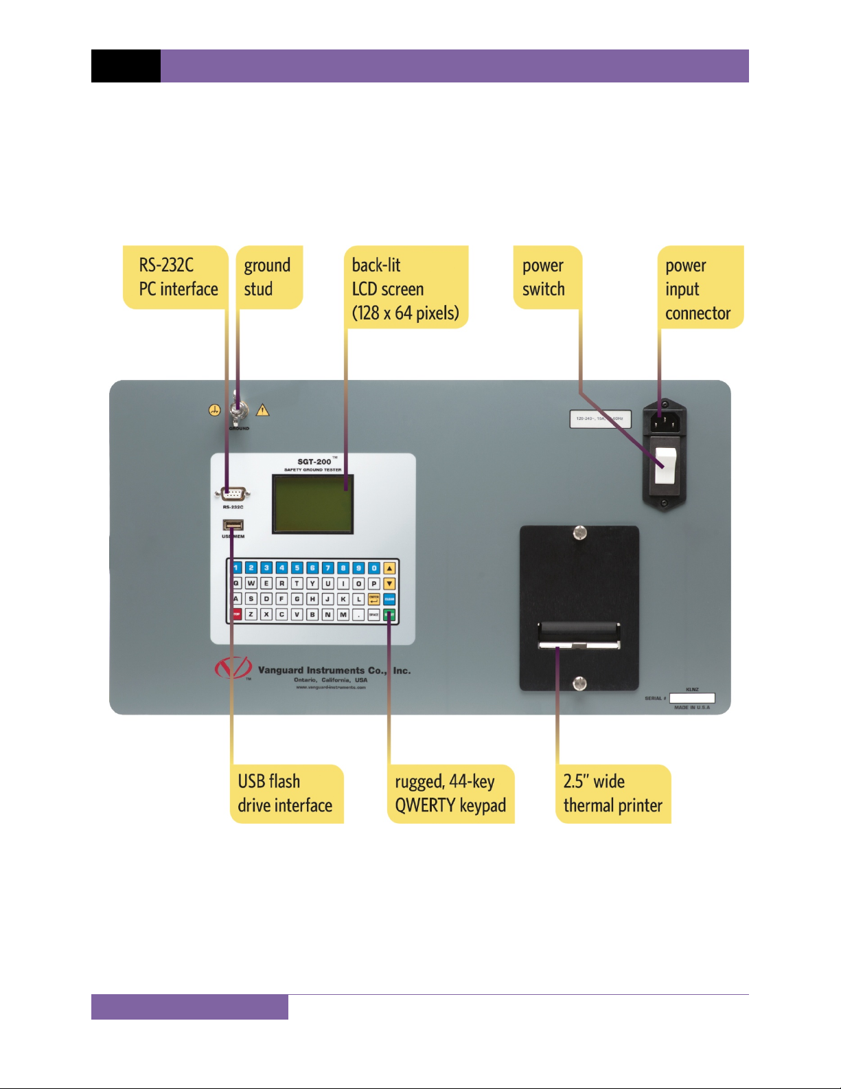
1.3 SGT-200 Controls and Indicators ..................................................................................... 5
2.0 PRE-TEST SETUP ................................................................................................................... 6
2.1 Operating Voltages .......................................................................................................... 6
2.2 LCD Screen Contrast Control ............................................................................................ 6
3.0 OPERATING PROCEDURES ................................................................................................... 7
3.1 Lid Removal ...................................................................................................................... 7
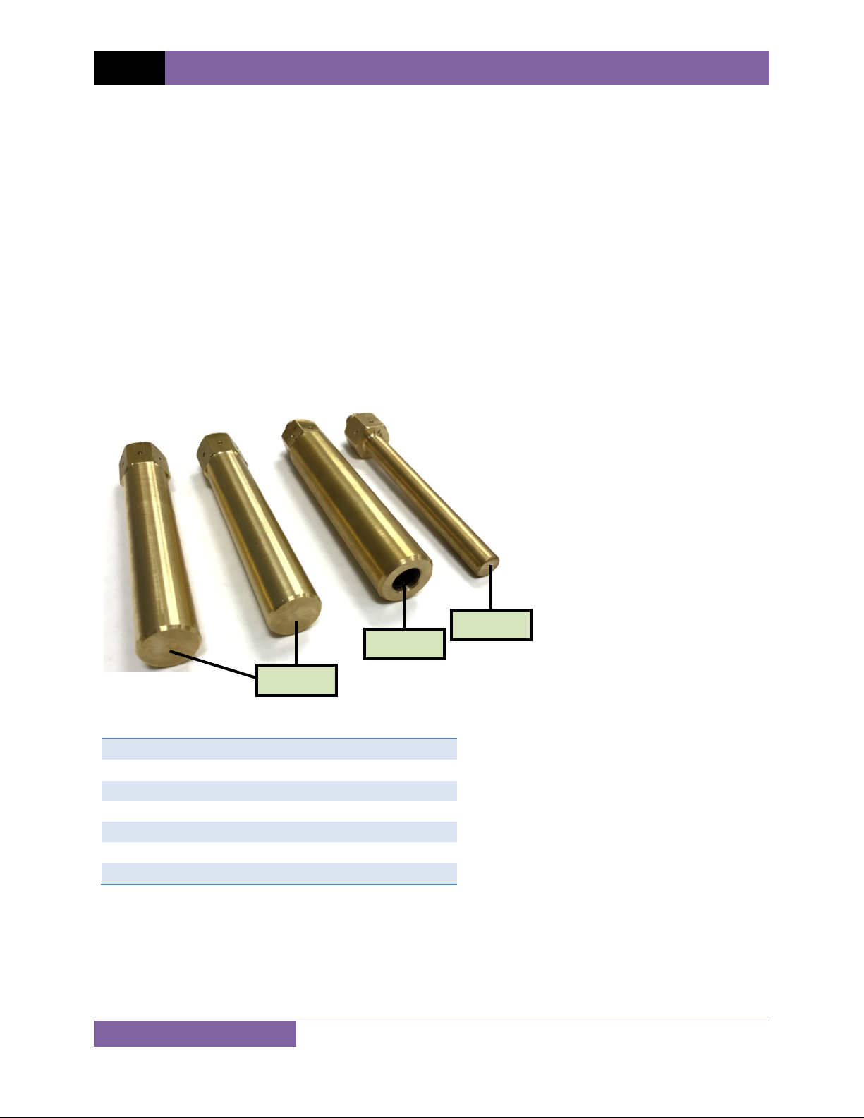
3.2 Cable Connection Post and Sense Wire Installation ........................................................ 9
3.4 Setting the Interface Language ...................................................................................... 12
3.5 Setting the Option to Print the Calibration Expiration Date .......................................... 13
3.6 Setting the Units of Measure ......................................................................................... 15
3.7 Testing Procedures ........................................................................................................ 17
3.7.1. Entering Test Record Header Information ............................................................. 17
3.7.2. Performing a Test ................................................................................................... 20
3.8 Working With Test Records ........................................................................................... 26
3.8.1. Viewing the Contents of the Working Memory ..................................................... 26
3.8.2. Saving Test Results to a Test Record ...................................................................... 28
3.8.3. Restoring a Test Record From Flash EEPROM ........................................................ 30
3.8.4. Restoring a Test Record From a USB Flash Drive ................................................... 34
3.8.5. Copying Test Records to a USB Flash Drive ............................................................ 36
3.8.6. Printing the Test Record Directory ......................................................................... 39
3.8.7. Erasing Test Records from the Unit's Flash EEPROM ............................................. 42
3.8.8. Erasing Test Records from a USB Flash Drive ......................................................... 47
4.0 Getting the Latest Firmware, Software, and Manuals....................................................... 50
LIST OF FIGURES
Figure 1. SGT-200 Controls and Indicators ..................................................................................... 5
Figure 2. Sample Test Report Printout with Calibration Expiration Date ..................................... 14
Figure 3. Sample SGT-200 Test Results Printout .......................................................................... 25
Figure 4. Sample Thumb Drive Directory Printout ....................................................................... 41
Figure 5. Sample Internal Test Record Directory Printout............................................................ 41

REV 1.0
1
This doc
u
•
A ke
y
•
Men
u
• SGT-
2
• Whe
n
(opti
o
• War
n
W
A
• Imp
o
N
1.
2.
3.
4.
5.
1.
2.
3.
4.
5.
SGT-200
U
C
u
ment uses
y
, switch, or
u
names ar
e
2
00 screen
o
n
instructio
n
o
n 3 should
n
ing messag
e
A
RNING
W
a
o
rtant notes
OTE
No
OPTION 1
OPTION
2
OPTION
3
OPTION
4
OPTION 5
OPTION 1
OPTION
2
OPTION
3
OPTION
4
OPTION
5
U
SER’S MAN
C
ONVEN
T
t
he followi
n
knob on th
e
e
referenced
o
utput is sh
o
n
s are provi
d
be selected
e
s are indic
a
a
rning mes
s
are indicat
e
te details
2
3
4
5
2
3
4
5
UAL
T
IONS U
S
n
g conventi
o
e
SGT-200 is
as “MENU
N
o
wn as:
d
ed, the me
n
):
a
ted as:
s
age
e
d as:
S
ED IN T
H
o
ns:
indicated a
s
N
AME”
n
u item tha
t
H
IS DOC
U
s
[KEY], [
S
t
should be
s
U
MENT
S
WITCH],
[
s
elected is s
h
[
KNOB]
.
h
own in bold

SGT-200 USER’S MANUAL REV 1.0
2
1.0 INTRODUCTION
1.1 General Description and Features
The Vanguard SGT-200 Safety Ground Tester is a 200A DC micro-ohmmeter designed
specifically to measure the resistance of protective in-service grounding and jumper cable
assemblies. The SGT-200 can measure the resistance of the grounding cables, clamps and
ferrules. The measured resistance values can be compared against the calculated values (using
the ASTM 2249-03 standard) and a Pass/Fail result can be printed along with the measured
resistance values.
The SGT-200 can measure resistance value from 1 micro-ohm to 1000 milliohms. A typical test
requires the two ends of the safety ground cable to be connected to the terminals of the SGT-
200. The resistance of the cable and ferrules can then be measured. If the cable size, cable
length and temperature are provided, the SGT-200 will determine if the cables passes or fails
the test and a pass/fail indicator will be printed on the test report.
Test results are printed on the unit's built-in 2.5” thermal printer. A 44-key QWERTY-style
rugged membrane keypad is used to input information and control the SGT-200. A back-lit
graphic LCD screen (128 x 64 pixels) is used to display menus and test results.
The SGT-200 can store up to 100 test records in its internal memory. It also features a USB Flash
drive interface port that can be used to store test data in a USB flash drive (not included). The
SGT-200 also features an RS-232C port that is used for factory diagnostics and calibration.
Test records can be reviewed and printed on a PC using the provided Vanguard VUS software.
In-Service Cable Testing
The SGT-200 measures the total resistance value of the cable under test and then compares it
to the calculated value to determine the Pass or Fail result. In order to calculate the total
resistance value, the user is first prompted for the cable size, cable length, and cable
temperature. Total resistance (Rm) is calculated in accordance with the ASTM F2249-03
standard using the formula below:
Rm = 1.05 RL + 2Y = 1.05 RL + 320 µΩ*
Where:
Y = Resistance of clamps, ferrule, and portions of the cable inside the ferrule, in milliohms*
L = Cable length in feet (ferrule to ferrule measurement to the nearest inch)
R = Cable resistance, in milliohms/foot
* NOTE: The clamp and ferrule resistance value of 160 µΩ is used per the ASTM-F2249-03
standard.

REV 1.0 SGT-200 USER’S MANUAL
3
The SGT-200 will calculate the maximum resistance value of the cable under test, measure the
resistance value and compare this value against the limit. The resistance value and a PASS or
FAIL result can be printed on the thermal printer.
Test Cable Sizes and Length
Typical Safety Ground Cable sizes are #2, 1/0, 2/0, and 4/0. The test cable length, ranging from
1' to 50' per table 2 in the F2249-03 standard, is entered by the user. Cable size and length can
be entered in either English or Metric units.
Test Record Storage
The SGT-200 can store 100 test records internally. Each test record contains test header
information, test cable size, test cable length, temperature, test current, and cable resistance.
Test records can also be stored on a USB flash drive via the unit's USB flash drive interface.
Included Connection Posts
Ordering Information
Part No. Description
9133-UC SGT-200 unit and cables
9133-SC SGT-200 shipping case
8000-0228 Standard cable stud set, 1" diameter (2 pcs)
8000-0229 Elbow adapter, female, 1/2" diameter (1 pc)
8000-0230 Bushing adapter, male, 1/2" diameter (1 pc)
TP3-CS TP3 thermal printer paper (36 rolls)
8000-0228
8000-0229
8000-0230

1.2
S
PHY
S
T
T
E
T
E
C
O
CAB
L
NO
S
GT-200 T
e
S
ICAL SPECI
F
INP
U
RESISTANC
E
T
EST CURRE
N
A
TES
T
E
ST RECORD
E
E
ST RECORD
PC
S
O
MPUTER IN
T
TEM
P
CONNECTI
O
L
E
S
AND ACC
E
W
TE
The
a
tem
p
e
chnical S
p
TYPE
P
F
ICATION
S
D
W
U
T POWER
1
E
READING
RANGE
1
(
N
T RANGE
1
t
CCURACY
1
T
VOLTAGE
5
DISPLAY
b
v
KEYPAD
r
INTERNAL
STORAGE
1
E
XTERNAL
STORAGE
u
OFTWARE
W
T
ERFACE
S
o
PRINTER
b
SAFETY
d
P
ERATURE
O
S
HUMIDITY
9
ALTITUDE
2
O
N POSTS
T
E
SSORIE
S
p
e
d
OPTIONS
s
W
ARRANTY
o
a
bove specif
p
erature of
2
p
ecificatio
P
ortable Micro
-
D
imensions:
2
W
eight: 31 lbs
1
00 240 Vac,
1
micro-ohm to
max 1.5 millio
h
1
0A 200A (s
e
hermally prote
c
1
0A 49.9A: 1
%
5
Vdc
b
ack-lit LCD s
c
v
iewable in bri
g
r
ugged, 44-key
1
00 test record
u
p to 999 test
r
W
indows®-ba
s
o
ne RS-232C
P
b
uilt-in 2.5” wid
d
esigned to m
e
O
perating: -1
0
S
torage: -30°
C
9
0% RH @ 40
°
2
,000 m (6,56
2
T
wo 2”/3” diam
p
ower cord, gr
o
e
lbow adapter,
d
iameter (1 pc
)
s
hipping case
o
ne year on pa
ications are
2
5°C (77°F).
ns
-
Ohmmeter
2
1”W x 8”H x 1
4
. (14.1 Kg)
50/60 Hz
1000 millioh
m
h
ms @ 200A,
4
e
lectable in 1A
c
ted DC powe
r
%
±2 micro-oh
c
reen (128 x 6
4
g
ht sunlight an
d
"QWERTY"-s
t
s
r
ecords on ext
e
s
ed analysis s
o
P
C interface, o
n
e thermal prin
t
e
et IEC 61010
(
0
°C to +50°C (
+
C
to +70°C (-2
2
°
C (104°F) no
n
2
ft) to full safet
eter posts
o
und cable, st
a
female, 1/2" d
)
rts and labor
valid at no
m
Specificatio
n
SGT-200
4
” D (53.3 cm
x
m
s
4
50 milliohms
@
steps);
r
supply
ms, 50A 200
4
pixels)
d
lo
w
-light lev
e
t
yle membran
e
e
rnal USB flas
h
o
ftware is inclu
d
n
e USB flash
d
t
er
(
1995), UL 61
0
+
15°F to +122
°
2
°F to +158°F)
n
-condensing
y specification
s
a
ndard cable s
t
iameter (1 pc),
m
inal opera
t
n
s may cha
n
USER’S MA
x
20.3 cm x 3
5
@
10A, 1000
m
A: 1% ±1 micr
o
e
ls
e
keypad
h
drive
d
ed with purch
a
d
rive interface
0
10-a, and CA
S
°
F)
s
t
ud set, 1" dia
m
bushing adap
t
t
ing voltage
a
n
ge without
NUAL RE
5
.6 cm)
m
illiohms @ 1
A
o
-ohm
a
se price
S
-C22.2 stand
a
m
eter (2 pcs),
t
er, male, 1/2"
a
nd at a
prior notice
V 1.0
4
A
)
a
rds
.

REV 1.0 SGT-200 USER’S MANUAL
5
1.3 SGT-200 Controls and Indicators
The SGT-200’s controls and indicators are shown in Figure 1. The purpose of the controls and
indicators may seem obvious, but users should familiarize themselves with them before using
the SGT-200. Accidental misuse of the controls will usually cause no serious harm. Users should
also familiarize themselves with the safety summary information found on the front page of
this User’s Manual.
Figure 1. SGT-200 Controls and Indicators

SGT-200 USER’S MANUAL REV 1.0
6
2.0 PRE-TEST SETUP
2.1 Operating Voltages
The SGT-200 operate on voltages between 120-240 Vac, 50/60 Hz.
2.2 LCD Screen Contrast Control
To increase the LCD screen contrast, press and hold the [] key for two seconds. Release the
button when the desired contrast level has been reached.
To decrease the LCD screen contrast, press and hold the [] key for two seconds. Release the
button when the desired contrast level has been reached.
2.3 Safety Ground
Always ground the SGT-200 to the substation ground before connecting cables to the unit.
2.4 Printer Paper
The SGT-200’s built-in thermal printer uses 2.5" wide thermal paper for printing test results. To
maintain the highest print quality and to avoid paper jams, the use of thermal paper supplied
by Vanguard Instruments Company is highly recommended. Additional paper can be ordered
from the following sources:
Vanguard Instruments Co, Inc.
1520 S. Hellman Avenue
Ontario, CA 91761
Tel: 909-923-9390
Fax: 909-923-9391
Part Number: TP3-CS
BG Instrument Co.
13607 E. Trent Avenue
Spokane, WA 99216
Tel: 509-893-9881
Fax: 509-893-9803
Part Number: VIC TP-3 paper

REV 1.0 SGT-200 USER’S MANUAL
7
3.0 OPERATING PROCEDURESLid Removal
The SGT-200 features a lid that can be easily removed for greater convenience during testing.
Follow the steps below to remove the lid:
a. Remove the set screw from the back of the left lid hinge.
b. Rotate the lid open approximately 45 degrees to align the enclosure tab with the groove
in the lid hinge.
LID OPEN AT 90°
(Tab NOT aligned with groove) tab
groove
LID OPEN AT 45°
(Tab aligned with groove) tab
groove
remove screw

SGT-200 USER’S MANUAL REV 1.0
8
c. Slide the lid horizontally to the right.
d. Continue to slide the lid horizontally to the right to completely remove.

REV 1.0
9
3.1
C
Follow t
h
a. S
e
p
SGT-200
U
C
able Con
n
h
e steps bel
o
e
lect the ca
b
osts into th
e
NOTE
Ma
k
pos
t
U
SER’S MAN
n
ection Po
o
w to install
b
le connecti
e
SGT-200 f
e
k
e sure the
p
t
s will yield
i
UAL
st and Se
n
the cable c
o
on posts to
e
male recep
t
p
osts are sc
r
i
naccurate t
e
inst
n
se Wire I
n
o
nnection p
be used wit
t
acles on ea
r
ewed in co
m
e
st results.
fe
m
alled cable con
n
n
stallation
osts and se
n
h the test c
a
ch side of t
h
m
pletely an
d
m
ale receptacle
n
ection post
n
se wires:
a
bles. Scre
w
h
e SGT-200.
d
firmly. Loo
w
the connec
se connecti
o
tion
o
n

b. C
s
h
c. C
d. C
onnect the
s
h
own belo
w
onnect the
S
onnect the
g
NOTE
Th
e
s
ense wires
w
:
S
GT-200 gr
o
g
round cabl
e
e
cable doe
s
to the cabl
e
o
und and po
w
e
to be test
e
s
NOT need
t
e
connectio
n
w
er cables.
e
d to the ca
b
t
o be un-wo
SGT-200
n
posts on b
o
b
le connecti
und and ca
n
se
n
ground
USER’S MA
o
th sides of
t
on posts as
n
remain coi
n
se wire
cable to be tes
t
NUAL RE
t
he SGT-20
0
shown belo
w
led.
t
ed
V 1.0
10
0
as
w
:

REV 1.0 SGT-200 USER’S MANUAL
11
3.2 Setting the Date and Time
To set the date and time:
a. Start from the “START-UP” menu:
Press the [3] key (SETUP).
b. The following screen will be displayed:
Press the [4] key (SET TIME)
c. The following screen will be displayed:
Type in the date using the keypad. The following screen will be displayed:
Enter the time using the keypad. When the time has been entered, you will be
immediately returned to the “START-UP” menu.
ENTER TIME
HH:MM:SS
ENTER DATE
MM-DD-YY
1. RECORD ID
2. REVIEW RECORD
3. SAVE/RESTORE RECORD
4. set time
5. set language
6. CAL NOTICE ON/OFF
7. SET UNITS
1.CERT TEST
2.QUICK TST
3.SETUP
time: 10:11:12 23°C
date: 12/29/16 73°F

SGT-200 USER’S MANUAL REV 1.0
12
3.3 Setting the Interface Language
Follow the steps below to set the interface language (English):
a. Start from the “START-UP” menu:
Press the [3] key (SETUP).
b. The following screen will be displayed:
Press the [5] key (SET LANGUAGE).
c. The following screen will be displayed:
Select the preferred interface language by pressing the corresponding key on the
keypad ([1], [2], or [3]). The interface language will be set and a confirmation screen
will be displayed as shown below:
Press any key to return to the “START-UP” menu.
ENGLISH SET
1. ENGLISH
2. TURKISH
3. SPANISH
1. RECORD ID
2. REVIEW RECORD
3. SAVE/RESTORE RECORD
4. set time
5. set language
6. CAL NOTICE ON/OFF
7. SET UNITS
1.CERT TEST
2.QUICK TST
3.SETUP
time: 10:11:12 23°C
date: 12/29/16 73°F

REV 1.0 SGT-200 USER’S MANUAL
13
3.4 Setting the Option to Print the Calibration Expiration Date
The SGT-200 can print the unit's factory calibration expiration date at the bottom of test
reports if desired. Follow the steps below to configure this option:
a. Start from the "START-UP" menu:
Press the [3] key (SETUP).
b. The following screen will be displayed:
Press the [6] key (CAL NOTICE ON/OFF)
c. The following screen will be displayed:
1. Press the [1] key to enable to option. The following screen will be displayed:
The calibration date printing option will be enabled and you will be returned to
the "START-UP" menu. Figure 2 shows a sample test report with the calibration
expiration date printed at the bottom.
CAL DATE PRINTING
ENABLED.
CAL DATE PRINTING:
1. ENABLE
2. DISABLE
1. RECORD ID
2. REVIEW RECORD
3. SAVE/RESTORE RECORD
4. set time
5. set language
6. CAL NOTICE ON/OFF
7. SET UNITS
1.CERT TEST
2.QUICK TST
3.SETUP
time: 10:11:12 23°C
date: 12/29/16 73°F

SGT-200 USER’S MANUAL REV 1.0
14
2. Press the [2] key to disable the option. The following screen will be displayed:
Press any key to return to the "START-UP" menu.
Figure 2. Sample Test Report Printout with Calibration Expiration Date
CAL DATE PRINTING
DISABLED.

REV 1.0
15
3.5
S
The SGT
-
preferre
d
a. S
t
P
b. T
P
c. T
P
SGT-200
U
S
etting the
-
200 suppor
t
d
units of m
e
t
art from th
ress the
[3]
he followin
g
ress the
[7]
he followin
g
ress the
[1]
NOTE
In
M
ad
j
50
SET
1. ENGLI
S
2. METRI
C
1. RECOR
D
2. REVIE
W
3. SAVE/
R
4. set t
i
5. set l
a
6. CAL N
O
7. SET U
N
1.CE
R
2.QU
I
3.SE
T
time: 1
0
date: 1
2
U
SER’S MAN
Units of
M
t
s both Met
e
asure:
e "START-U
P
key (SETUP
g
screen will
key (SET U
N
g
screen will
key to sele
c
M
etric mod
e
j
usted in inc
mm
2
, 70 m
m
UNITS:
S
H
C
D
ID
W
RECORD
R
ESTORE
R
i
me
a
nguage
O
TICE ON
/
N
ITS
R
T TE
S
I
CK T
S
T
UP
0
:11:12
2
/29/16
UAL
M
easure
ric and Engl
i
P
" menu:
).
be displaye
N
ITS)
be displaye
c
t English or
e
, the cable
rements of
1
m
2
, and 95
m
R
ECORD
/
OFF
S
T
S
T
23
°
C
73
°
F
i
sh units. Fo
d:
d:
the
[2]
key
length will
b
1
/10 m. Ca
b
m
m
2
)
llow the ste
p
to select M
b
e in meters
b
le sizes will
p
s below to
etric.
and the len
also be in
M
select your
gth can be
M
etric (35 m
m
m
2
,

SGT-200 USER’S MANUAL REV 1.0
16
d. The following screen will be displayed (English units shown for this example):
Press any key to return to the "START-UP" menu.
ENGLISH MODE SET!

REV 1.0 SGT-200 USER’S MANUAL
17
3.6 Testing Procedures
3.6.1. Entering Test Record Header Information
You can enter the test record header information before performing tests. The record header
includes identifying information such as the company, station, circuit, manufacturer, etc. Once
the header information has been set, it will apply to all subsequent test records. Follow the
steps below to enter the test header information:
a. Start from the “START-UP” menu:
Press the [3] key (SETUP).
b. The following screen will be displayed:
Press the [1] key (RECORD ID).
c. The following screen will be displayed:
Type the company name using the keypad. Press the [ENTER] key when you are done
typing the company name.
COMPANY:
_
↑/↓TO POSITION
"ENTER" TO ACCEPT
1. RECORD ID
2. REVIEW RECORD
3. SAVE/RESTORE RECORD
4. set time
5. set language
6. CAL NOTICE ON/OFF
7. SET UNITS
1.CERT TEST
2.QUICK TST
3.SETUP
time: 10:11:12 23°C
date: 12/29/16 73°F
Table of contents
Other Vanguard Test Equipment manuals