Vanguard EZCT-2000 User manual

EZCT-2000TM
DIGITAL CURRENT-TRANSFORMER TESTER
USER’S MANUAL
Vanguard Instruments Company, Inc.
1520 S. Hellman Ave.
Ontario, California 91761, USA
TEL: (909) 923-9390
FAX: (909) 923-9391
October 2009
Revision 3

EZCT-2000 USER’S MANUAL REV 3
i
SAFETY SUMMARY
FOLLOW EXACT OPERATING PROCEDURES
Any deviation from the procedures described in this User’s Manual may create one or more
safety hazards, may damage the EZCT-2000, or cause errors in the test results. Vanguard
Instruments Company, Inc. assumes no liability for unsafe or improper use of the EZCT-2000.
All safety precautions provided in this manual must be observed during all phases of testing
including test preparation, test lead connection, actual testing, and test lead disconnection.
SAFETY WARNINGS AND CAUTIONS
The EZCT-2000 can produce a voltage up to 2,000 Vac that can cause severe injury and/or
equipment damage. Due to this reason, the EZCT-2000 shall be used only by trained operators.
The EZCT-2000’s X output terminals are rated to 2,000 Vac working voltage. Any voltage above
2,000 Vac will damage the input circuitry. Please see section 3.2 for further information.
All devices under test shall be off-line and fully isolated. Never attempt to test any current
transformer still connected to a circuit. All current transformer terminals shall be isolated
before conducting any test with the EZCT-2000.
Always ground the EZCT-2000 to a substation ground before connecting the test cables to a
transformer.
DO NOT MODIFY TEST EQUIPMENT
To avoid the risk of introducing additional or unknown hazards, do not install substitute parts or
perform any unauthorized modification to any EZCT-2000 test unit. To ensure that all designed
safety features are maintained, it is highly recommended that repairs be performed only by
Vanguard Instruments Company factory personnel or by an authorized repair service provider.
Unauthorized modifications can cause safety hazards and will void the manufacturer’s
warranty.
WARNING
Do not remove test leads during a test. Failure to heed this warning can result in electrical
shock to personnel and damage to the equipment.

REV 3 EZCT-2000 USER’S MANUAL
ii
TABLE OF CONTENTS
CONVENTIONS USED IN THIS DOCUMENT ..................................................................................... 1
1.0 INTRODUCTION.................................................................................................................... 2
1.1 General Description and Features ................................................................................... 2
1.2 Furnished Accessories...................................................................................................... 3
1.3 Technical Specifications ................................................................................................... 4
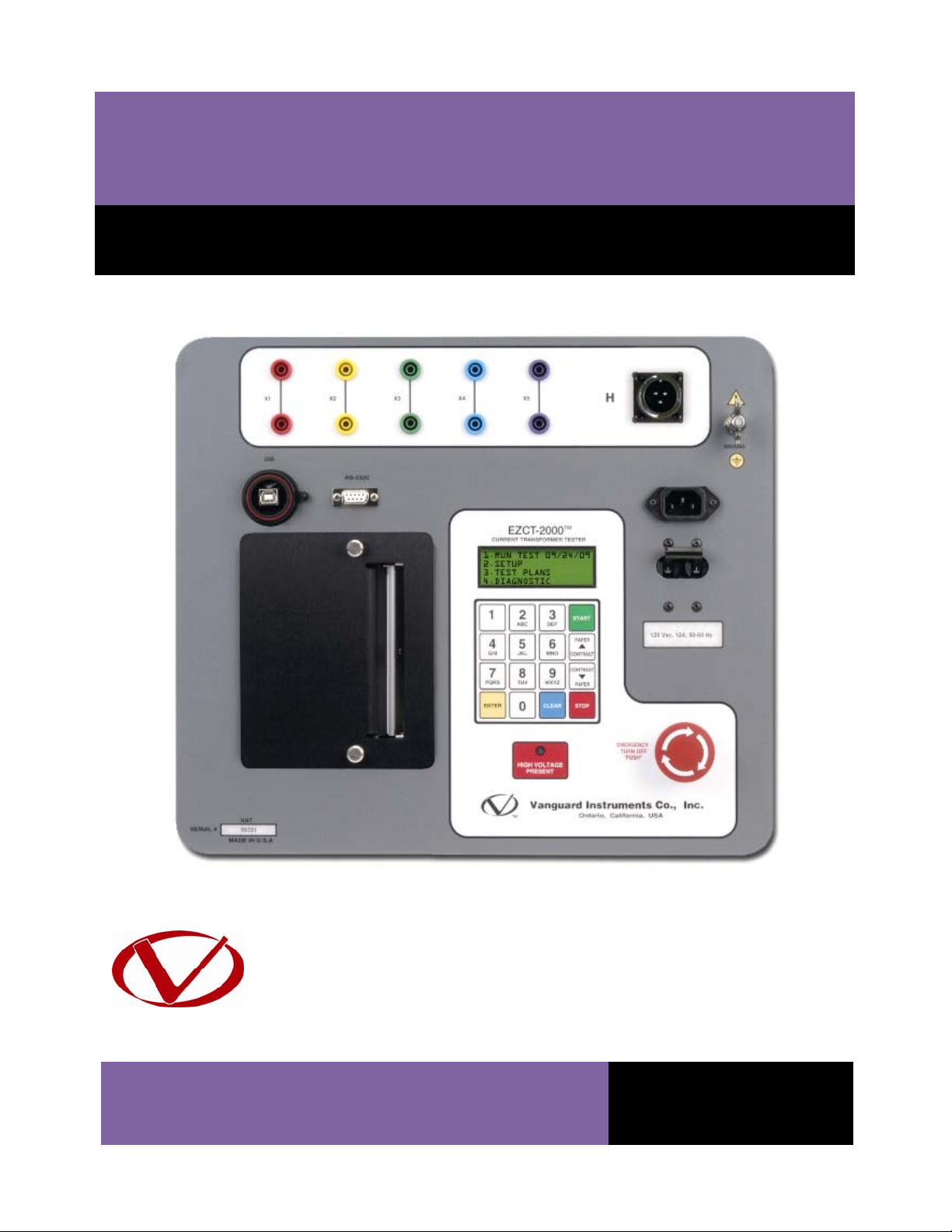
1.4 EZCT-2000 Controls and Indicators.................................................................................. 5
2.0 PRE-TEST SETUP ................................................................................................................... 7
2.1 Operating Voltages .......................................................................................................... 7
2.2 LCD Screen Contrast Control............................................................................................ 7
2.3 Printer Paper Control....................................................................................................... 7
2.4 Printer Paper.................................................................................................................... 7
3.0 OPERATING PROCEDURES ................................................................................................... 9
3.1 EZCT-2000 Cable Connections ......................................................................................... 9
3.2 EZCT-2000 X Input Voltage Warning.............................................................................. 11
3.3 Performing Tests............................................................................................................ 12
3.3.1. Entering Test Record Header Information ............................................................. 12
3.3.2. Performing Resistance, Excitation, and Ratio Tests ............................................... 15
3.4 Working With Test Records ........................................................................................... 24
3.4.1. Restoring and Printing a Test Record From Flash EEPROM ................................... 24
3.4.2. Printing a Restored Test Record............................................................................. 27
3.4.3. Printing a Directory of Test Records Stored in the EZCT-2000’s Memory ............. 28
3.4.4. Erasing Test Records From the Flash EEPROM ...................................................... 30
3.5 Working With Test Plans................................................................................................ 32
3.5.1. Extracting the Test Plan From a Test Record ......................................................... 32
3.5.2. Printing a Directory of Test Plans Stored in the EZCT-2000’s Memory.................. 34
3.5.3. Printing a Test Plan................................................................................................. 36
3.5.4. Erasing Test Plans From the Flash EEPROM........................................................... 38
3.5.5. Loading a Test Plan from the EZCT-2000’s Flash EEPROM..................................... 40
3.5.6. Running a Test Using a Loaded Test Plan............................................................... 41
3.5.7. Unloading a Test Plan from the Working Memory ................................................ 44
4.0 CHANGING SETUP PARAMETERS ....................................................................................... 45
4.1 Setting the Knee Point Marker ...................................................................................... 45
4.2 Selecting the Buried CT in Transformer Delta Option ................................................... 47
4.3 Setting the Clock ............................................................................................................ 50
5.0 DIAGNOSTICS, VERIFICATION, AND TROUBLESHOOTING ................................................. 51
5.1 Performing a Diagnostics Test ....................................................................................... 51
5.2 Verifying the EZCT-2000’s VxSense Circuit Using an External Meter............................ 53
5.3 Verifying the EZCT-2000’s IxSense Circuit Using an External Meter............................. 54
5.4 Quickly Verifying the EZCT-2000’s Turns Ratio Circuit .................................................. 55
5.5 Troubleshooting Guide .................................................................................................. 56

EZCT-2000 USER’S MANUAL REV 3
iii
LIST OF TABLES
Table 1. EZCT-2000 Technical Specifications .................................................................................. 4
Table 2. Functional Descriptions of EZCT-2000 Controls and Indicators........................................ 6
Table 3. Descriptions of Tabulated Test Results Elements ........................................................... 22
Table 4. Description of Test Plan Elements .................................................................................. 37
LIST OF FIGURES
Figure 1. EZCT-2000 Controls and Indicators.................................................................................. 5
Figure 2. Typical EZCT-2000 Excitation and Ratio Test Cable Connection...................................... 9
Figure 3. Bushing CT Connection on Delta Transformer .............................................................. 10
Figure 4. Bushing CT Connection on Y Transformer ..................................................................... 10
Figure 5. Sample CT Name Plate................................................................................................... 11
Figure 6. Typical EZCT-2000 Tabulated Report Printout............................................................... 21
Figure 7. Typical EZCT-2000 Graphic Report................................................................................. 23
Figure 8. Typical EZCT-2000 Graphic Report with Multiple Plot Curves....................................... 23
Figure 9. Typical Internal Test Record Directory Printout ............................................................ 29
Figure 10. Typical EZCT-2000 Flash EEPROM Test Plan Directory Printout.................................. 35
Figure 11. Typical Test Plan Printout ............................................................................................ 37
Figure 12. Graphic Report Showing Knee Point Marker............................................................... 46
Figure 13. Buried CT in a Delta Transformer Illustration 1 ........................................................... 48
Figure 14. Buried CT in a Delta Transformer Illustration 2 ........................................................... 48
Figure 15. EZCT-2000 VxVerification Test Connections ............................................................... 53
Figure 16. EZCT-2000 IxVerification Test Connections................................................................. 54
Figure 17. EZCT-2000 Turns Ratio Verification Test Connections ................................................ 55

REV 3 EZCT-2000 USER’S MANUAL
1
CONVENTIONS USED IN THIS DOCUMENT
This document uses the following conventions:
•A key or switch on the EZCT-2000 is indicated as [KEY] and [SWITCH].
•Menu options are referenced as (MENU OPTION).
•Screen and menu names are referenced as “SCREEN/MENU NAME”.
•The terms “test record” and “test shot” are used interchangeably.
•EZCT-2000 LCD screen output is shown as:
•When instructions are provided, the menu item that should be selected is shown in bold as
shown below (option 3 should be selected):
•Warning messages are indicated as:
WARNING
Warning message
•Important notes are indicated as:
NOTE
Note details
1. OPTION 1
2. OPTION 2
3. OPTION 3
4. OPTION 4
1. OPTION 1
2. OPTION 2
3. OPTION 3
4. OPTION 4
Table of contents
Other Vanguard Test Equipment manuals
Popular Test Equipment manuals by other brands

Redtech
Redtech TRAILERteck T05 user manual

Venmar
Venmar AVS Constructo 1.0 HRV user guide

Test Instrument Solutions
Test Instrument Solutions SafetyPAT operating manual

Hanna Instruments
Hanna Instruments HI 38078 instruction manual

Kistler
Kistler 5495C Series instruction manual

Waygate Technologies
Waygate Technologies DM5E Basic quick start guide

StoneL
StoneL DeviceNet CK464002A manual

Seica
Seica RAPID 220 Site preparation guide

Kingfisher
Kingfisher KI7400 Series Training manual

Kurth Electronic
Kurth Electronic CCTS-03 operating manual

SMART
SMART KANAAD SBT XTREME 3G Series user manual

Agilent Technologies
Agilent Technologies BERT Serial Getting started