VBT-60/80 Operating Procedures
6
1.0 INTRODUCTION
1.1 Applicability
This manual applies to the Model VBT-60™ and Model VBT-80™ (hereafter, VBT), made by
Vanguard Instruments Company, Inc.
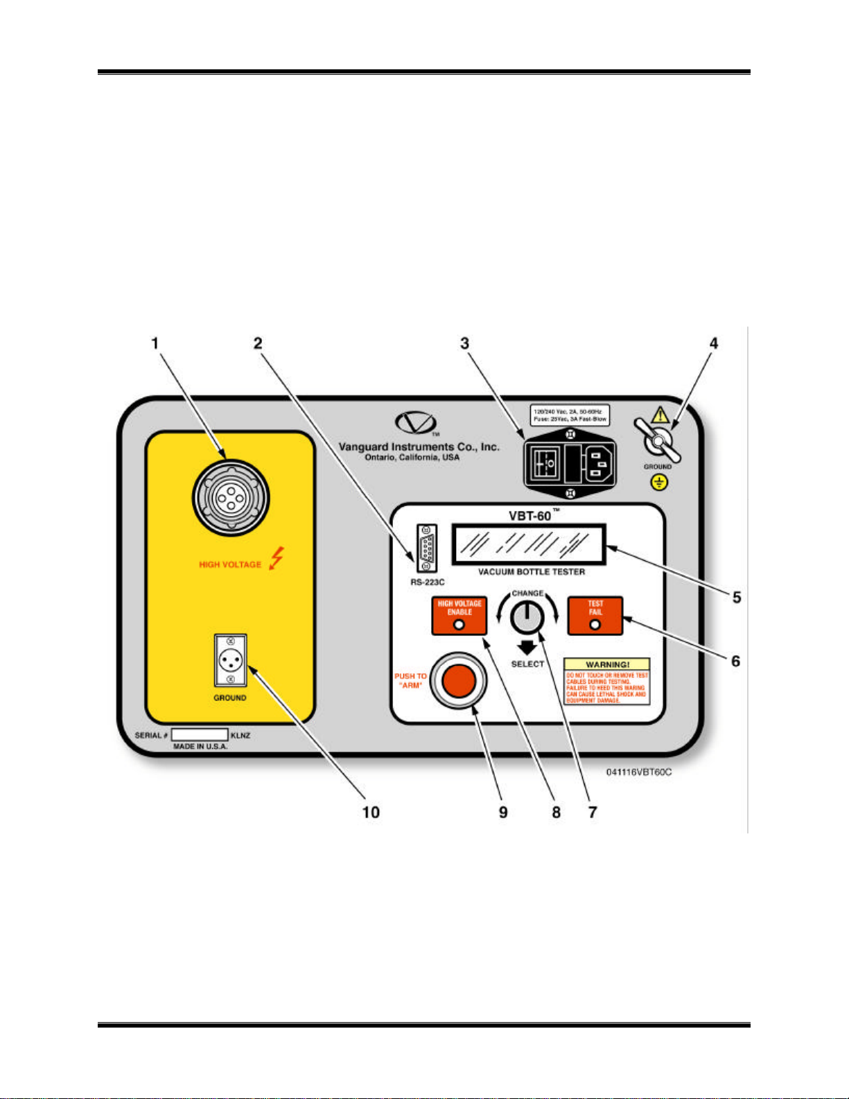
1.2 General Description
The VBT-60 and VBT-80 are light-weight DC vacuum bottle testers made by Vanguard
Instruments Company. The VBT tests the vacuum bottle integrity by applying a DC voltage
across the bottle under test. A simple “PASS” or “FAIL” message indicates the condition of the
bottle after each test. The VBT is field-portable, rugged, and is easily operated by first-time users
having a minimum of training. It features a “Turn-then-Press” control knob for entering test
parameters and control functions.
Turning the knob scrolls through a menu of possible options (which display in sequence) and
pressing the knob activates the selected function
A 2-line by 16-character LCD alpha/numeric readout is used for displaying control-option
menus, and test results. The operation requires little more than connecting test leads to the
vacuum bottle, selecting the desired test voltage and test duration.
1.3 Functional Description
Using a voltage multiplier, the VBT-60 generates a programmable test voltage from 10,000 V dc
to 60,000 V dc (or 10,000 V dc to 80,000 for VBT-80) with 5,000 V dc steps.
The test voltage can be applied at different time durations: 5 seconds, 10 seconds, 30 seconds, 1
minute, or 2 minutes. Test current is monitored by the VBT electronics during test. If this test
current exceeds a preset threshold, the test is terminated and a test “FAIL” message is displayed.
The over-current threshold is programmable at 100 micro-amps, or 200 micro-amps, or 300
micro-amps.
A “FAIL” message will be displayed on the LCD and “TEST FAIL” indicator will be
illuminated on the front panel.
A test is considered successful if the selected test voltage was applied for the full test duration
and the test current did not exceed the preset threshold.
The VBT’s LCD displays “PASS” message along with the test voltage and test duration if a test
is successful.
1.4. Furnished Test Accessories
The VBT is supplied with one 10-foot long high-voltage test cable, one 10-foot long voltage-
return lead with alligator clamps. A Ground cable, power cord and a shipping case are also
included with each VBT.
http://www.51082245.com