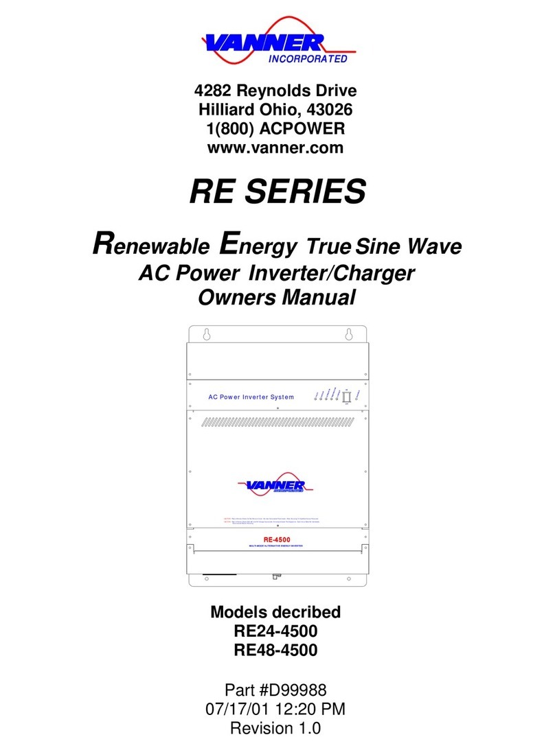
Vanner TS Series User manual
Other Vanner Inverter manuals
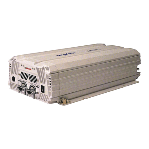
Vanner
Vanner LSC12-2000 User manual
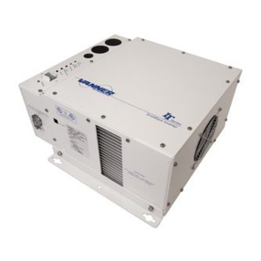
Vanner
Vanner IT12-1400 User manual
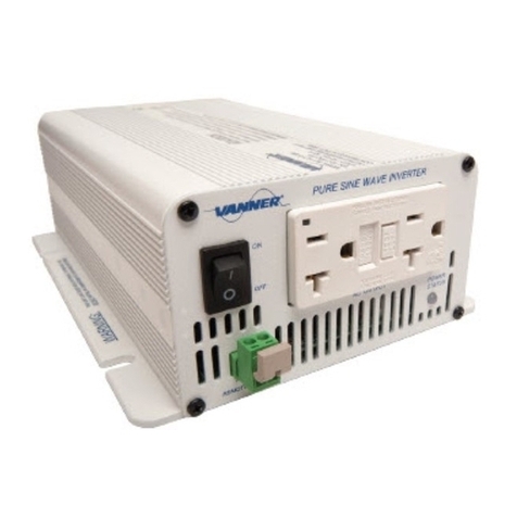
Vanner
Vanner VLT Series User manual

Vanner
Vanner Bravo 2600 User manual

Vanner
Vanner TS Series User manual
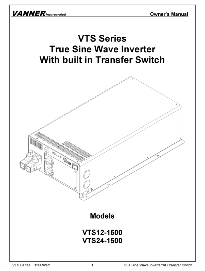
Vanner
Vanner VTS12-1500 User manual
Vanner
Vanner LifeSine LSC12-1100 User manual

Vanner
Vanner VLT12-300 User manual

Vanner
Vanner 20-1050CUL User manual
Vanner
Vanner IQ Series User manual

Vanner
Vanner BRAVO 1050 User manual
Vanner
Vanner VLT12-600 User manual

Vanner
Vanner Bravo 1800 User manual
Vanner
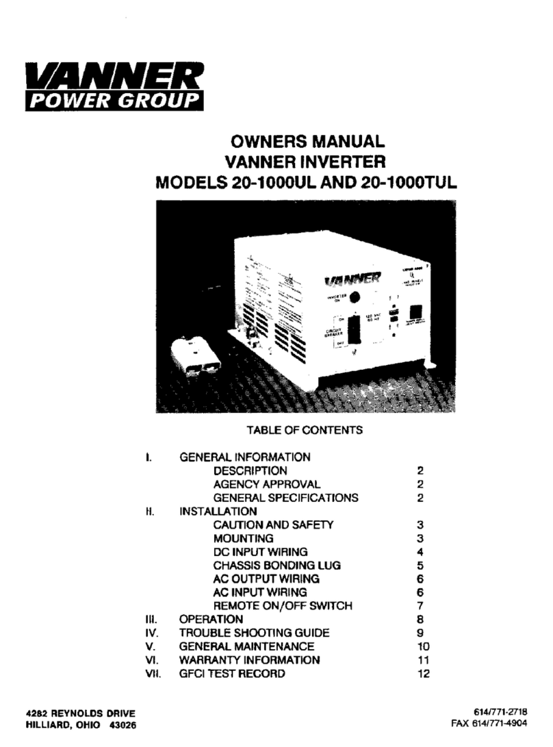
Vanner 20-1000UL User manual
Vanner
Vanner 20-1000TUL User manual

Vanner
Vanner VLT12-600 User manual

Vanner
Vanner Bravo 1800 User manual
Vanner
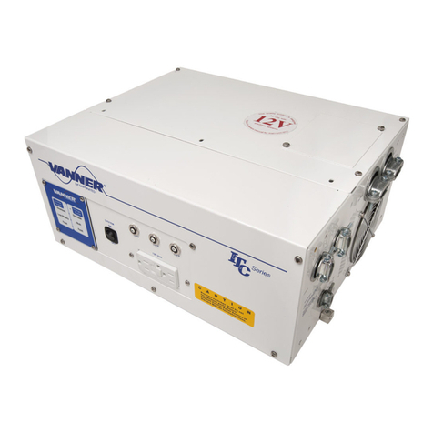
Vanner ITC12-2100 User manual
Vanner
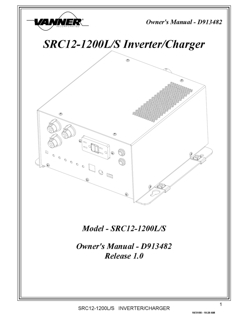
Vanner SRC12-1200L User manual
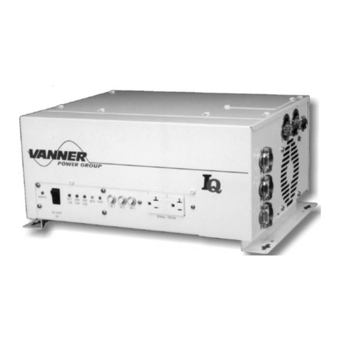
Vanner
Vanner IQ12-2600 User manual
Popular Inverter manuals by other brands

MULTIQUIP
MULTIQUIP GDP-5H Operation and parts manual

Astrel Group
Astrel Group Power Reducer Installation and instruction manual

GoWISE
GoWISE PS1007 user manual

Promate
Promate PM13500D ES Operator's manual

Mastervolt
Mastervolt WHISPER 3.5M3000 RPM user manual

Mitsubishi Electric
Mitsubishi Electric FR-A7AZ instruction manual
