primer first. Otherwise chemical interaction and decomposition could occur.
If you want to protect your VARIPROP with Antifouling,
use only Antifouling which needs a
shaft plus the prop anode. We recommend the replacement of the anode once a
year.
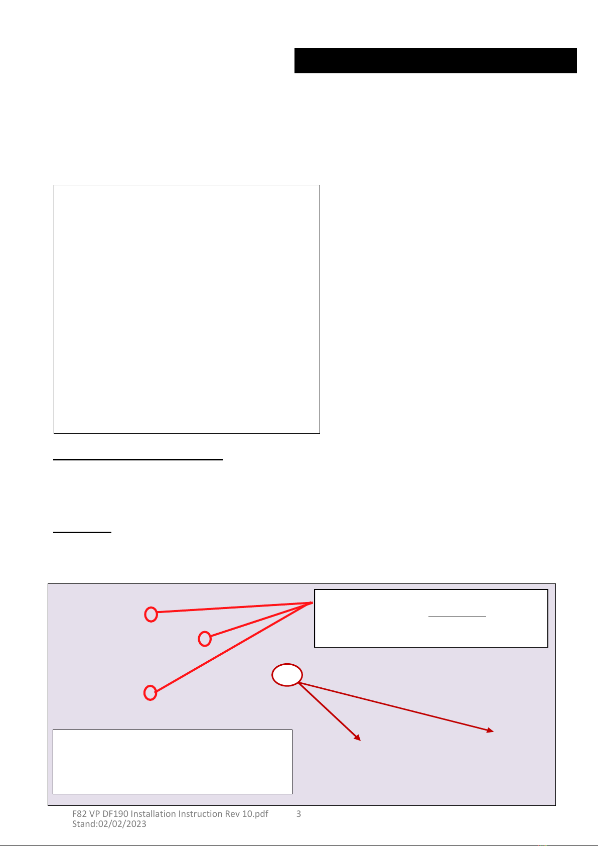
The propeller must be protected from electrolytic corrosion by fitting the usual zinc anodes on the
The propeller body must always be completely filled with a high viscosity grease.
We recommend
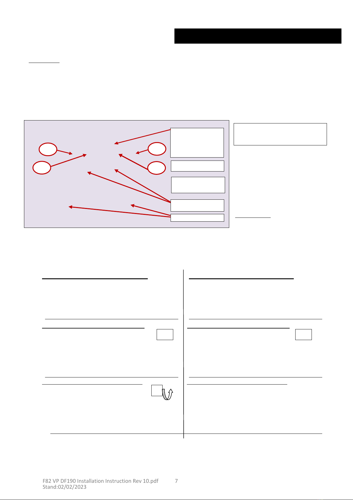
feathering blades. This is normal and not a problem or a defect
of your
VARIPROP.
When going from ahead to astern or the opposite,
you can hear the turning-noise of the
substantially lengthen the service life of your propeller
gears.
rpm’s (max.1200rpm)
between gears to allow smooth reversing of rotation without binding.
This will
When going from ahead to astern or the opposite, it is necessary to idle down and shift at low
to the gears, shortening their life.
WARNING:
It is important to follow the instructions below carefully so as to avoid excessive load and shock
Check the clutch discs of the transmission. They could be worn
out.
way detrimental.
in the owners manual of your transmission.
A larger amount of lever travel is in
no
lever,
between the neutral position and end positions for forward and reverse can be found
not too short.
The amount of lever travel,
as measured at the pivot point of the actuating
Check shifting movement of the transmission lever.
Make sure that the
shifting travel is
Check low idle of the engine. It should be 800 to 900 rpm in
idle.
points below:
TROUBLE SHOOTING:
If the propeller does not work in forward or reverse go systematically through the
stays in sailing
position.
VARIPROP XLS range,
we highly recommend to fit a shaft lock to ensure the propeller feathers and
work,
you
most
likely
need
to
fit
a
shaft
lock.
For
large
yachts,
equipped
with
a
propeller
from
our
usually
enough
to
feather
the
propeller
instantly
into
sailing
position.
If
this
procedure
does
not
This procedure generates higher oil pressure and prevents shaft rotation. This small-scale friction is
sailing
position
without
a
shaft
lock
as
you
turn
off
the
engine
with
forward
gear
still
clutched
in.
Please
note
that
98%
of
our
delivered
VARIPROP
propellers
for
hydrolic
gear
boxes
feather
into
will not feather. You can actually use this feature to drive a shaft generator.
DO NOT stop
the engine while it turns in reverse. In this case the blades will stay in the reverse position and
Once the prop is feathered, it is better to shift the transmission to neutral.
In that case start the engine again and repeat the steps above.
If the propeller is not feathered in the sailposition the shaft will freewheel like with a fixed propeller.
stop spinning the shaft to feather the blades in the
sailposition.
Stop the engine while still engaged in forward. The remaining oil pressure of the transmission will
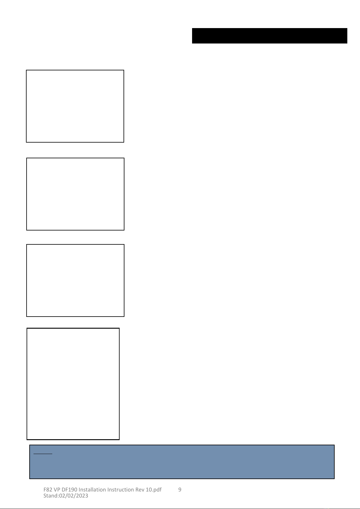
Power at 3 to 4 knots in
forward.
VARIPROP sailposition with hydraulic transmission:
the shaft.
Now engage in Neutral
again.
Stop the engine, turn it off
and engage the transmission in reverse to stop the freewheeling of
Power at 3 to 4 knots in
forward.
VARIPROP sailposition with mechanical gear-box:
THE BEST WAY TO FEATHER THE PROPELLER IN THE SAILPOSITION IS:
into gear the blades will engage in either forward or reverse.
The VARIPROP feathers automatically when the shaft rotation is stopped. After engine start-up and shifting
synthetic
grease
typ
TW.2
GEL
or
mineral
multi-purpose
grease
EP/SAL
(see
servicing
page
9)
F82 VP DF190 Installation Instruction Rev 10.pdf
Stand:02/02/2023