VAUPEL 2000 GS User manual

OPERATING MANUAL 2000 GS V7.4/20-EN
Page| 1
Spray gun 2000 GS
Art. no.: 20301, 20313

OPERATING MANUAL 2000 GS V7.4/20-EN
Page| 2
Thank you very much for the trust you have placed in us and our products.
Please read the operating manual first before working with
the spray gun.
This operating and maintenance manual contains important information required
for the safe and trouble-free operation of your spray gun. Therefore always keep
this operating manual with the spray gun.
General notices:
This spray gun was developed for certain applications. We explicitly point out that
this spray gun must not be modified and/or used in a way that does not corre-
spond to its intended use.
Content:
1. Technical data ………………………………………………………………………………………... 3
2. Extent of delivery ….……………………………………………………………………………… 3
3. Intended use …………………………….……………………………………………………….…3
4. Features ………………………………………………………………………………………….. 3
5. Safety instructions ………………………………………………………………..…………………. 3
6. Installation ……………………………………………………………………………..……………….. 4
7. Maintenance and care …………………………………………………………….………………. 5
8. Storage ……………………………………….…………………………………………..……………… 5
9. Troubleshooting ……………………………………………………………………….……………… 5
10. Warranty terms …………………….…………………………………………………………………. 5
11. Address……………………………………………………………………………………………………. 6
12. EC-declaration of conformity ………………………………………………………………….. 7
13. Technical drawing and spare parts list…………………………………………………… 8

OPERATING MANUAL 2000 GS V7.4/20-EN
Page| 3
1. Technical data
2. Extent of delivery
Spray gun, steel riser pipe, operating manual
3. Intended use
This light-weight spray gun is a compressed air operated tool for manual use. It
is suitable for processing stone chip and underbody protection from 1 litre cans.
4. Features
The effectiveness of the 2000 GS spray gun is based on the Venturi effect. For
this purpose, an air stream is used which accelerates when the air nozzle flows
through and thus generates negative pressure in the adjoining riser pipe. The
spray mass is thereby sucked in and sprayed out via the nozzle by the air flow.
5. Safety instructions
Protect yourself and the environment by taking appropriate precautions against
the risk of accidents and observe the following instructions in your own
interest:
•The operator must ensure proper operation
•Do not bring compressed air, stone chip or underbody protec-
tion into contact with skin or eyes.
•Keep children and pets away from the operating area.
•Never direct the spray jet at animals, people or yourself.
•No manipulations, emergency repairs or misappropriations
may be carried out on the gun.
•Spray guns may only be operated and maintained by in-
structed persons.
•Repairs must only be carried out by qualified persons.
Description
2000 GS
Operating pressure
2-8 bar
Maximum pressure
8 bar
Bottle volume
1 litre
Connection thread
¼“
Compressed air connection
Quick coupling
Jet adjustment
no
Measurements 2000 GS
227 x 329 x 53 mm
Net weight
approx. 512 g
Gross weight
approx. 637 g
Required air quality
Filtered, condensate-free

OPERATING MANUAL 2000 GS V7.4/20-EN
Page| 4
The following applies to all maintenance and repair work:
•It is essential to disconnect the spray gun from the compressed
air connection.
•Only use original spare parts.
•The maximum working pressure must not be exceeded (see
point 1 "Technical data"). The working pressure must be ad-
justed via a (filter) pressure reducer.
•Only use compressed air as energy source.
•The compressed air connection may only be made via a quick
coupling.
•When working with the spray gun, wear the necessary protec-
tive clothing, protective goggles, work gloves, ear protection if
necessary and a respirator mask.
•If there are leaks in the device or other operating faults, the
device must be disconnected from the compressed air supply
immediately and the cause of the fault must be eliminated.
•Open fire, sparks or smoking is prohibited.
•Beware of flammable materials.
•Stone chip and underbody protection remains as well as
cleaning media must be disposed of in an environmentally
friendly manner.
•The disposal of the compressed air device must be carried out
according to the valid legal regulations.
6. Installation
Screw in the supplied steel riser pipe hand-tight. Pierce the protective foil of
the 1 litre can and dip the riser pipe into the spraying material. Screw the 1 litre
can into the plastic threaded cap of the spray gun hand-tight. Take care not to
overtighten the thread!
Connect the spray gun to the compressed air supply via the quick coupling. By
pressing the trigger you put the spray gun into operation.
The spray pattern can be influenced by the following factors:
•Distance between spray nozzle and object
•Angle of the gun to the object
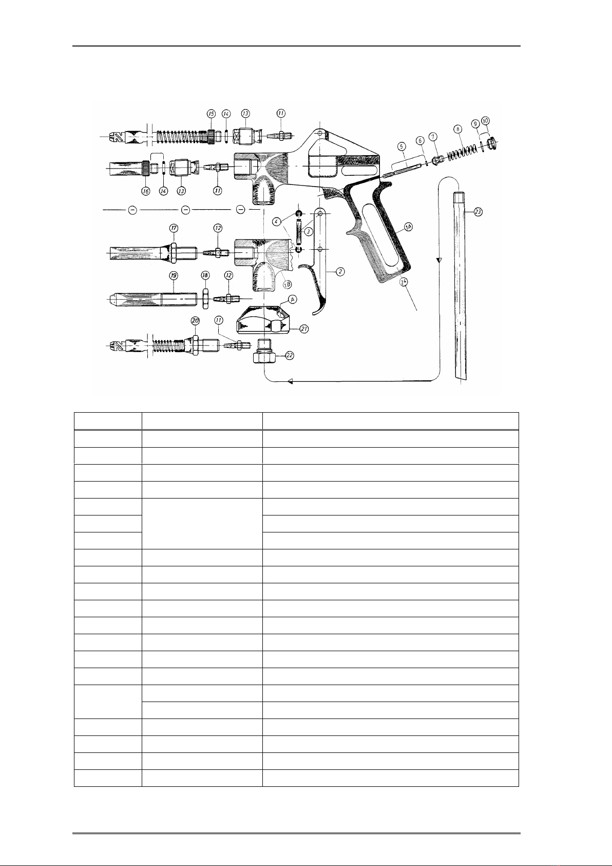
Optionally with this spray gun you have the possibility to preserve cavities. For
this purpose the brass spray pipe (2900 GS) must be separated from the
threaded connection piece (H26) and replaced by an optionally available cavity
spray hose (2900 H).

OPERATING MANUAL 2000 GS V7.4/20-EN
Page| 5
7. Maintenance and care
After each use, disconnect the device from the compressed air supply and thor-
oughly clean it. We recommend benzine or commercially available terpene-
based cleaners. Do not use aggressive cleaners! Following the maintenance in-
structions will ensure a long service life and trouble-free operation for this qual-
ity product.
Attention:
Pay attention to a proper disposal of the residues, which arise
during the maintenance and care.
8. Storage
The compressed air tool must be stored under the following conditions:
•If residual material is present, store only upright.
•Carefully clean the spray gun after each use.
•Store in a dry and dust-free place.
•Do not expose to liquids and/or aggressive chemicals.
•Keep out of the reach of children.
9. Troubleshooting
In all cases of malfunction, please first check whether there is sufficient com-
pressed air available, whether the spray material can still be processed, wheth-
er the expiry date has passed or whether the material has dried out.
•Gun sprays messy
Possible cause: Spray pipe, riser pipe and/or ventilation hole dirty.
Solution: Clean parts.
•Gun does not spray any material
Possible cause: Riser pipe and/or spray pipe clogged.
Solution: Clean clogged parts.
•Air escapes from the spray nozzle even though the trigger is in its initial
position.
Possible cause: Valve bolt is jammed.
Solution: Pour oil onto the valve bolt and/or into the compressed air intake.
Operate the trigger several times.
10. Warrenty terms
The basis for all warranty claims is the complete spray gun and the proof of
purchase. Damage caused by improper handling of the spray gun is not covered
by the warranty.
If you have any questions, please indicate the type description or the article
number of the spray gun.
•In conformity with legal regulations, you receive a 24-month warranty on
all products against material and manufacturing defects.

OPERATING MANUAL 2000 GS V7.4/20-EN
Page| 6
Excluded from the warrenty:
•Wear parts.
•Damage caused by improper use.
•Damage caused by lack of maintenance.
•Damage caused by dirt.
•Damage caused by untreated compressed air.
If warranty claims are made, the spray gun must be in its original condition.
11. Address
In case of service your sales representative is at your side or contact the
following address:
Vaupel GmbH
Gerätebau & Drucklufttechnik
Am Forsthaus 6
35713 Eschenburg-Simmersbach
Germany
Telephone: +49 (0) 2774 80069-0
E-Mail: info@vaupel-gmbh.de
Internet: www.vaupel-gmbh.de
Notice: We reserve the right to make technical changes. Illustrations may differ
from the original. We assume no liability for printing errors.

OPERATING MANUAL 2000 GS V7.4/20-EN
Page| 7
12. EC-declaration of conformity
EC-declaration of conformity
In accordance with the EC Machine Directive 2006/42/EC,
Type of gun: Suction gun Compressed air
Type designation: Type 2000 GS
Type description: Spray gun
Article number Manufacturer: 20301, 20313
Is developed, designed and manufactured in conformity with the above EC
Directives, under the general responsibility of
Company: Vaupel GmbH
Gerätebau & Drucklufttechnik
Am Forsthaus 6
35713 Eschenburg-Simmersbach
The technical documentation is complete.
The following harmonised standard has been applied:
DIN EN ISO 12100 - Sicherheit von Maschinen –Allgemeine Gestaltungsleit-
sätze - Risikobeurteilung und Risikominderung
The operating manual belonging to the machine is available in the original
version and in the respective national language.
Simmersbach, 01.04.2020
Place, Date Signature, Managing director

OPERATING MANUAL 2000 GS V7.4/20-EN
Page| 8
13. Technical drawing and spare parts list
Pos.
Article no.
Description
1
---
Gun body
2
50 3909 005
Trigger
3
30 1102 006
Lever axis
4
60 3100 029
Lock washer
5
80158
Valve bolt
6
O-ring 1.5 x 0.75 mm
7
Valve seal
8
60 3103 003
Spring for valve
9
60 4100 062
O-ring 8 x 1 mm
10
30 1120 002
Locking screw
11
30 1424 009
Air nozzle 2.0 mm
13
10 1431 001
Connection piece H26
14
60 4100 011
O-ring 8 x 2 mm
15
29002
Cavity spray hose (2900 H)
16
30 1124 001
Brass spray pipe (2900 GS)
21
40 4112 010
Threaded cap standard (black)
40 4112 012
Threaded cap USA (red)
21 A
---
Ventilation hole
22
30 1432 018
Fixing screw m 10 x 1 mm
23
60 3129 001
Riser pipe 253 mm
24
---
¼" Connection thread
This manual suits for next models
2
Table of contents
Other VAUPEL Paint Sprayer manuals

VAUPEL
VAUPEL 3200 K1 User manual

VAUPEL
VAUPEL 3000 FG User manual

VAUPEL
VAUPEL 2000 HG User manual

VAUPEL
VAUPEL 3000 DV User manual

VAUPEL
VAUPEL 3200 DVR User manual

VAUPEL
VAUPEL 2000 KMS User manual

VAUPEL
VAUPEL 3300 HSDR User manual

VAUPEL
VAUPEL 3300 DPF User manual

VAUPEL
VAUPEL 2000 KD User manual

VAUPEL
VAUPEL 2000 HKD User manual