7. $##()$#
?(The unit ay so eti es produce condensation which ust be
drained away. A 21.5/22 dia pipe outlet is provided on this unit).
$)6$%)$#!!)$'')#'#$##)$'(:0/53800"";')9
)5'#%%"*()$##))$)%%'$%')(7%##)
$#)%$()$#($)(*%%!.#-)')*)#5')$(#5
?
If the ducting is installed as shown in Fig A, the drain ust be connected to
the left-hand outlet. If the ducting is installed as shown in Fig. B, the drain
ust be connected to the right-hand outlet. The unused drain outlet ust
be capped off.
• The drainage pipe ust be installed with a continuous fall fro the cabinet
to the external household drainage point and a wet or dry trap ust be fitted to prevent return air penetration.
• If any part of the condensate drain pipe passes through an unheated space, it ust be insulated with the equiv-
alent of at least 25 of insulating aterial with a ther al conductivity of 0.04 W/ K.
?Where ducting is installed in an *#)
space, all of the ducts should be insulated.
Where ducting is installed in a )
space, only the cold ducts should be insu-
lated. i.e. the supply duct fro outside and
the extract duct fro the unit to the outside.
?The duct layout ust be designed to suit
the require ents of the ventilation/heat
recovery syste and building layout.
?Where rigid duct is used, it should be in-
stalled using the least nu ber of fittings to
ini ise air flow resistance. Where possible,
final connection to the grilles and unit should be
ade with a flexible connection.
?Where flexible ducts are used, ensure that:
- lengths of ducting longer than necessary
are #$)used
- the duct is stretched so that it is s ooth
and straight
- where bends are necessary, they have l
large radii (ie avoid sharp bends)
-
the duct is not crushed if in a restricted area
? Where ducting passes through a fire partition, suitable fire da pers "*() be installed to prevent the
trans ission of fire through the duct.
Page 5
!)'!$##)$#
6)(%%!#("*()')#!!,'#"*()$#$'")$*''#)*!)$#(#!!%9
%!!()#'(#*!#*!)$#(5
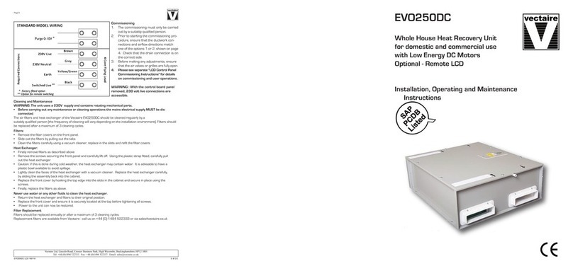
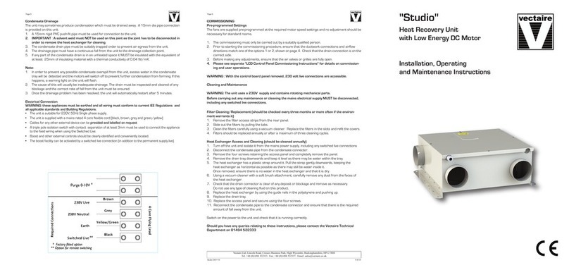
• The unit is suitable for 230V, 50Hz Single phase supply.
• The unit is supplied with6
9 A ains rated 4 core flexible cord (black, brown, grey and green/yellow) and 2 core 0-10v cables for purge
switching, $'an external connector box.
Cables for any other external device will be %'$+#!!!$#'&*()
• A triple pole isolation switch with contact separation of at least 3 ust be used to connect the appliance to the
fixed wiring when using the Switched Live.
• Boost controls ust not be located within 1 etre of a cooker or where they ay be affected by excessive heat or
oisture.
• Boost and other external controls should be clearly identified and conveniently located.
? The boost facility can be activated by a switched live connection (in addition to the per anent supply live). The switched
live can be operated by a variety of external devices, including:
- PIRFF (passive infra red)=
- DRH240 (dyna ic re ote hu idistat)=
- THM (ther ostat)=
- a light switch (if ore than one light switch is used, $#"*()$*!%$!(,);
- a re ote switch/pull cord
or via LCD control
(=PIRFF, DRH240 and THM ay have integral over-run ti er which controls the length of ti e that the fan will
continue to operate at its boost speed after the boost has been switched off.)
