manuals.online logo
Brands
  1. Home
  2. •
  3. Brands
  4. •
  5. Vectaire
  6. •
  7. Heating System
  8. •
  9. Vectaire Studio Assembly instructions

Vectaire Studio Assembly instructions

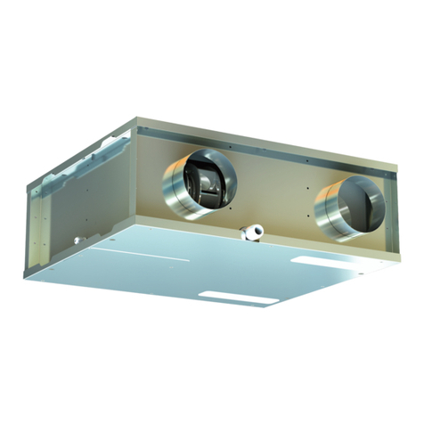
"Studio"
Heat Recovery Unit
with Low Energy DC Motor
Installation, Operating
and Maintenance Instructions
Condensate Drainage
The unit may sometimes produce condensation which must be drained away. A 15mm dia pipe connection
is provided on this unit.
1. A 15mm rigid PVC push-fit pipe must be used for connection to the unit.
2. IMPORTANT : A solvent weld must NOT be used on this joint as the joint has to be disconnected in
order to remove the heat exchanger for cleaning.
3. The condensate drain pipe must be suitab y trapped order to prevent air egress from the unit.
4. The drainage pipe must have a continuous fa from the unit to the drainage co ection point.
5. If any part of the condensate drain is in an unheated space it MUST be insu ated with the equiva ent of
at east 25mm of insu ating materia with a therma conductivity of 0.04 W/mK.
Note:
1. In order to prevent any possib e condensate overspi from the unit, excess water in the condensate
tray wi be detected and the motors wi switch off to prevent further condensation from forming. If this
happens, a warning ight on the unit wi f ash.
2. The cause of this wi usua y be inadequate drainage. The drain must be inspected and c eared of any
b ockage and the correct rate of fa from the unit must be ensured.
3. Once the drainage prob em has been reso ved, the unit wi automatica y restart after 5 minutes.
Electrical Connection
WARNING: these appliances must be earthed and all wiring must conform to current IEE Regulations and
all applicable standards and Building Regulations.
• The unit is suitab e for 230V, 50Hz Sing e phase supp y.
• The unit is supp ied with a mains rated 4 core f exib e cord (b ack, brown, grey and green/ye ow)
• Cab es for any other externa device can be provided and labelled on request
• A trip e po e iso ation switch with contact separation of at east 3mm must be used to connect the app iance
to the fixed wiring when using the Switched Live.
• Boost and other externa contro s shou d be c ear y identified and convenient y ocated.
• The boost faci ity can be activated by a switched ive connection (in addition to the permanent supp y ive).
Page 5 Page 6
COMMISSIONING
Pre-programmed Settings
The fans are supp ied pre-programmed at the required motor speed settings and no adjustment shou d be
necessary for standard rooms.
1. The commissioning must on y be carried out by a suitab y qua ified person.
2. Prior to starting the commissioning procedure, ensure that the ductwork connections and airf ow
directions match one of the options 1 or 2, shown on page 4. Check that the drain connection is on the
correct side.
3. Before making any adjustments, ensure that the air va ves or gri es are fu y open.
4. Please see separate "LCD Control Panel Commissioning Instructions" for details on commission-
ing and user operations..
WARNING : With the control board panel removed, 230 volt live connections are accessible.
Cleaning and Maintenance
WARNING: The unit uses a 230V supply and contains rotating mechanical parts.
Before carrying out any maintenance or cleaning the mains electrical supply MUST be disconnected,
including any switched live connections.
Filter Cleaning/Replacement (should be chec ed every three months or more often if the environ-
ment warrants it)
1. Remove the fi ter access strips from the rear pane .
2. S ide out the fi ters by pu ing the tabs.
3. C ean the fi ters carefu y using a vacuum c eaner. Rep ace the fi ters in the s ots and refit the covers.
4. Fi ters shou d be rep aced annua y or after a maximum of three c eaning cyc es.
Heat Exchanger Access and Cleaning (should be cleaned annually)
1. Turn off the unit and iso ate it from the mains power supp y, inc uding any switched ive connections
2. Disconnect the condensate pipe from the condensate connector.
3. Remove the four screws retaining the access pane and comp ete y remove the pane .
4. Remove the drain tray downwards and keep it eve as there may be water within the tray.
5. The heat exchanger has a p astic strap around it. Pu the strap gent y downwards, keeping the
heat exchanger as horizonta as possib e as there may sti be water inside it.
Once removed, ensure there is no water in the heat exchanger and that it is dry.
6. Using a vacuum c eaner with a soft brush attachment, carefu y remove any dust from the faces of
the heat exchanger.
7. Check that the drain connector is c ear of any deposit or b ockage and remove as necessary.
Do not use any type of c eaning f uid on this product.
8. Rep ace the heat exchanger by using the guide rai s in the po ystyrene and pushing up.
9. Rep ace the drain tray.
10. Rep ace the access pane and secure using the four screws.
11. Reconnect the condensate pipe to the condensate connector and ensure that there is the required
amount of fa away from the unit.
Switch on the power to the unit and check that it is running correct y.
Should you have any queries relating to these instructions, please contact the Vectaire Technical
Department on 01494 522333
Vectaire Ltd, Lincoln Road, Cressex Business Park, Hi h Wycombe, Buckin hamshire, HP12 3RH
Tel: +44 (0)1494 522333. Fax: +44 (0)1494 522337. Email: [email protected]
Studio 040119 E & O.E
"STUDIO" - HEAT RECOVERY UNIT
INSTALLATION AND OPERATING INSTRUCTIONS
SAFETY NOTICE
It is important to read this Instruction Manual carefully before installing or using the product. Following
these instructions will ensure that your ventilation system is installed, commissioned and used properly
and continues to operate effectively. Vectaire will not be held responsible and will not accept liability
for any damage caused to persons or property through failure to follow the guidance provided in this
manual. It should always be available with the product for easy reference.
Your unit SHOULD NOT be switched off (except during maintenance). It is designed to run continuously.
If it is switched off indoor pollutant and moisture levels may increase.
Studio: 125mm spigot, for continuous venti ation
Max airf ow 63 /s
GENERAL INFORMATION
The Vectaire Studio heat recovery system provides mechanica ven-
ti ation to bedrooms and bathrooms. It extracts sta e, contaminated
air from bathrooms, rep aces it with fresh air to the bedroom and
vents the sta e air to the outside.
Heat is rec aimed from the extracted air and used, via a heat
exchanger, to warm the incoming fresh air. The extract and intake
airstreams are comp ete y separate to avoid cross-contamination.
The system operates continuous y and is designed not be switched
off, except for maintenance purposes.
During norma operation, the unit produces a ow-vo ume airf ow,
creating a comfortab e, hea thy environment, with minimum energy consumption.
If additiona venti ation is required, (e.g. when a shower is in use), a boost faci ity is
inc uded which increases the airf ow rate. The boost can be operated automatica y
or manua y.
Insta ation of the unit is usua y above a cei ing or in a oft space and is connected
to air vents via hidden ductwork.
Each unit is commissioned individua y a owing its performance to be matched to the size of area to be ven-
ti ated.
STANDARD FEATURES
1. Variab e adjustment of ow (trick e) and boost speeds for optimum setting at insta ation.
2. Adjustab e overrun timer on boost setting - factory set to zero.
3. Adjustab e de ay-on timer, factory set to 2 minutes
4. Adjustab e night-time boost inhibitor set to operate from 10.00 p.m to 6.00 a.m
5. Mu tip e choice of externa devices for automatic or manua boost switching (e.g. ight switch, remote
switch/pu cord, PIRFF passive infra-red*, DRH240 humidistat*, THM thermostat*.)
*Note : Contact Vectaire for supp y of these items.
OPTIONAL ADDITIONAL FEATURE
BMS connections for remote motor shut-off.
Page 2
Incoming fresh air
Warmed fresh air
Extracted warm,
moist, stale air
Cooled outgoing
stale air
Studio
GENERAL SAFETY
PLEASE READ THESE INSTRUCTIONS FULLY, BEFORE ATTEMPTING ANY INSTALLATION
1. This product must not be used for any purpose other than that for which it was designed and shown
in this eaf et.
2. A packaging shou d be removed and the unit checked for damage. If any damage is found, contact
your supp ier.
3. This product wi norma y be fitted into a oft or cei ing void.
In order to comply with Construction (Design & Management) Regulations, sufficient access for
safe maintenance (recommended on an annual basis), or removal following installation, MUST be
provided for this product. See dimensions above.
4. The unit must NOT be insta ed:
- where there is excessive oi or grease
- where there are hazardous gases, iquids or vapours that are f ammab e or corrosive
- in ambient temperatures above 50ºC or ower than 5ºC
- in humidity eve s above 90% or in a wet environment
5. If any room from which air is extracted contains a fuel burning appliance, such as a central heating
boiler, then its flue must be of the sealed or balanced flue type, or allowance must be made for an
adequate supply of air into the room.
6. The mains supp y vo tage and power rating must comp y with the detai s on the product rating abe .
Page 3
DIMENSIONS - mm
N.B a c earance of
at east 200 mm
shou d be a owed
at the rear of the
unit in order to re-
pace fi ters. A
c earance of
220mm shou d be
a owed at bottom
of unit when in-
sta ed for access
to the heat ex-
changer
*236mm with mounting bracket on drain side
INSTALLATION
Installation must be carried out by a suitably qualified person and must comply with all current building
regulations and electrical installation regulations.
Mounting the unit
Before choosing the position for mounting, it is important to take into consideration the ductwork routes
and condensate drain route. The four spigots on the unit are marked for the four unique connections. The
unit can be supp ied eft or right-handed in order to match the required duct routes more easi y. (Factory
option on y.)
It is also essential that adequate access to the
product is provided for maintenance or removal
after installation. The entire access panel needs to
be removed for maintenance.
The unit is intended to be suspended from a cei ing
or simi ar fixture. Two identica fixing brackets are
supp ied with each unit. It is important that the unit
is attached to ithese brackets so that there is a s ope
down towards the condensation drain connector of
the product. When correct y fitted, the brackets wi
provide a drop of approximate y 15mm at the ower
end.
Duct and Duct Connections (refer to design drawing)
1.4 x 125mm nomina diameter spigots are provided for the connection of ducting. These are c ear y
marked for correct connection of the supp y and exhaust ducts.
2. Where ducting is insta ed in an unheated space, a of the ducts shou d be insu ated. Where ducting is
insta ed in a heated space, on y the co d ducts shou d be insu ated. i.e. the supp y duct from outside and
the extract duct from the unit to the outside.
3.The duct ayout must be designed to suit the requirements of the venti ation/heat recovery system and
bui ding ayout. If the ducting passes through a fire wa /barrier, suitab e fire dampers must be
insta ed.
4. Where rigid duct is used (preferab e), it shou d be insta ed using the east number of fittings to min
imise air f ow resistance. Where possib e, fina connection to the gri es and unit shou d be made with
a f exib e connection.
5. Where f exib e ducts are used, ensure that:
- duct runs are kept as short as possib e
- the duct is stretched so that it is smooth and straight
- where bends are necessary, they have arge radii (ie avoid sharp bends)
- the duct is not crushed if in a restricted area
Note: Whenever the unit is insta ed in c ose proximity to a bedroom or other habitab e space, we recom-
mend that sound attenuation is provided within the duct runs between the rooms and the unit. A ength of
1 metre of f exib e acoustic ducting wi be sufficient in most circumstances, but reference shou d be made
to the sound data provided for this product
Page 4
Diagram showing slope towards drain
Studio - option 1 (right hand drain) Studio - option 2 (left hand drain)
Other Vectaire Heating System manuals

Vectaire WHHR Maxi Assembly instructions

Vectaire

Vectaire WHHR Maxi Assembly instructions

Vectaire WHHR100DC-B Plus Assembly instructions

Vectaire

Vectaire WHHR100DC-B Plus Assembly instructions

Vectaire Mini DC Assembly instructions

Vectaire

Vectaire Mini DC Assembly instructions

Vectaire WHHR Midi Assembly instructions

Vectaire

Vectaire WHHR Midi Assembly instructions

Vectaire WHHR125DC Assembly instructions

Vectaire

Vectaire WHHR125DC Assembly instructions

Vectaire WHHR125DC Assembly instructions

Vectaire

Vectaire WHHR125DC Assembly instructions

Vectaire WHHR125DC Assembly instructions

Vectaire

Vectaire WHHR125DC Assembly instructions

Vectaire WHHR100/60DC Assembly instructions

Vectaire

Vectaire WHHR100/60DC Assembly instructions

Vectaire EVO250DC Assembly instructions

Vectaire

Vectaire EVO250DC Assembly instructions

Vectaire EVO90DC Assembly instructions

Vectaire

Vectaire EVO90DC Assembly instructions

Vectaire WHHRC180DC Assembly instructions

Vectaire

Vectaire WHHRC180DC Assembly instructions

Vectaire EVO350DC Operating and maintenance manual

Vectaire

Vectaire EVO350DC Operating and maintenance manual

Vectaire EVO220DC Assembly instructions

Vectaire

Vectaire EVO220DC Assembly instructions

Popular Heating System manuals by other brands

Mitsubishi Electric Ecodan FTC4 user guide

Mitsubishi Electric

Mitsubishi Electric Ecodan FTC4 user guide

Bosch C1050ES installation instructions

Bosch

Bosch C1050ES installation instructions

Xpelair Xcell 400 QV Installation and operating instructions

Xpelair

Xpelair Xcell 400 QV Installation and operating instructions

Marley MEnV 180 plus 60 Operating & assembly instructions

Marley

Marley MEnV 180 plus 60 Operating & assembly instructions

Baxi Assure Horizontal SHRU Installation and maintenance manual

Baxi

Baxi Assure Horizontal SHRU Installation and maintenance manual

Salda RIS 400 PW EKO 3.0 Technical manual

Salda

Salda RIS 400 PW EKO 3.0 Technical manual

Lifebreath RNC series Operation and installation manual

Lifebreath

Lifebreath RNC series Operation and installation manual

Mitsubishi Electric LGH-50RVS-E installation instructions

Mitsubishi Electric

Mitsubishi Electric LGH-50RVS-E installation instructions

Robur CALDARIA CONDENSING 100 Installation and use instructions

Robur

Robur CALDARIA CONDENSING 100 Installation and use instructions

Mitsubishi Electric Ecodan HUS210FTC4ST installation manual

Mitsubishi Electric

Mitsubishi Electric Ecodan HUS210FTC4ST installation manual

Frost Italy SIAL slim Operation manual

Frost Italy

Frost Italy SIAL slim Operation manual

Baxi Valor Fires 540 quick guide

Baxi

Baxi Valor Fires 540 quick guide

Viessmann VITOCELL 300-H Technical guide

Viessmann

Viessmann VITOCELL 300-H Technical guide

Dimplex DF2550 troubleshooting guide

Dimplex

Dimplex DF2550 troubleshooting guide

VOKERA Linea User instructions

VOKERA

VOKERA Linea User instructions

Energotech EnergoCassette ENC 300 Fitting instructions

Energotech

Energotech EnergoCassette ENC 300 Fitting instructions

Envirovent energiSava 500 Installation guide for engineer / installer

Envirovent

Envirovent energiSava 500 Installation guide for engineer / installer

STIEBEL ELTRON WPKI HK Operating and installation

STIEBEL ELTRON

STIEBEL ELTRON WPKI HK Operating and installation

manuals.online logo
manuals.online logoBrands
  • About & Mission
  • Contact us
  • Privacy Policy
  • Terms and Conditions

Copyright 2025 Manuals.Online. All Rights Reserved.