IT IS IMPORTANT THESE THESE INSTRUCTIONS
ARE READ FULLY BEFORE INSTALLATION
•This product shou d not be used for any purpose
other than that for which it was designed and as
shown in this eaf et.
•A packaging shou d be removed and the unit
checked for damage in transit. If there is any
damage, p ease contact your supp ier.
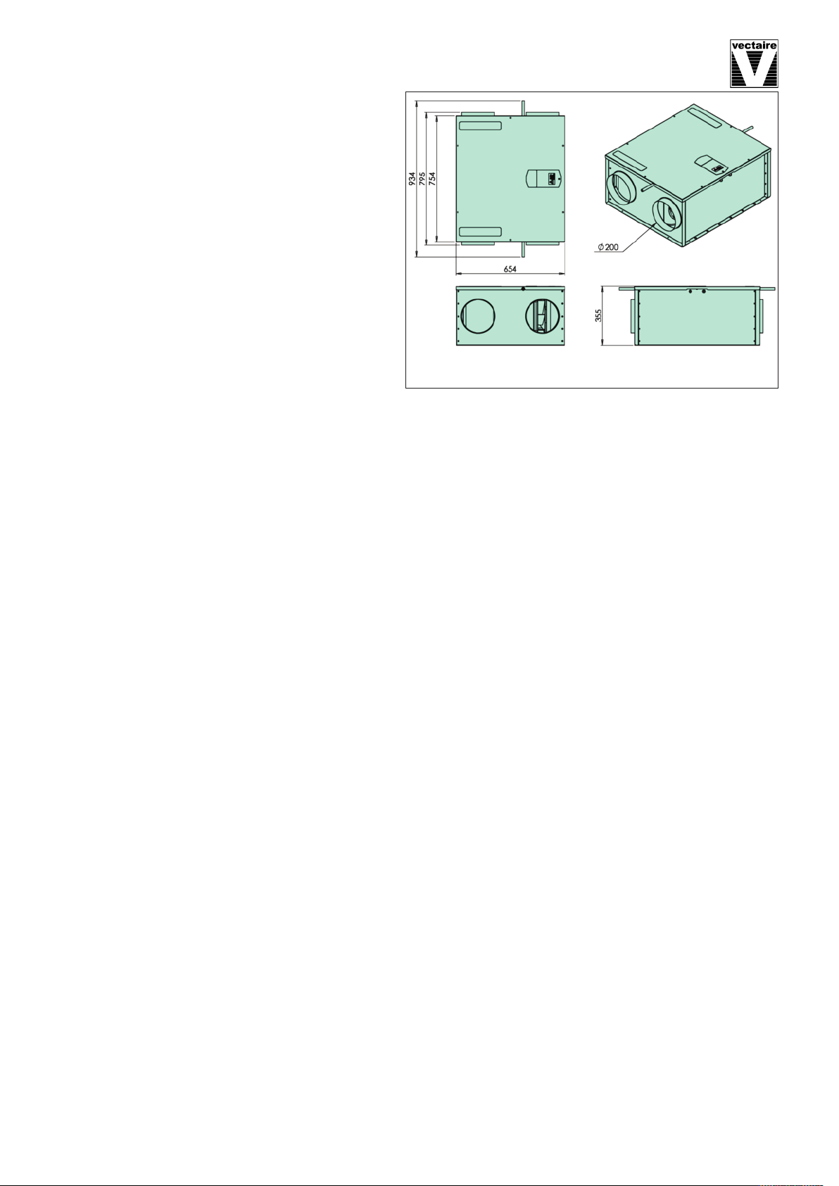
• The EVO350 wi genera y be fitted into a oft or
cei ing void. In order to comp y with Construction
(Design & Management) Regu ations, sufficient
access for safe maintenance (recommended on
an annua basis), or remova fo owing insta a-
tion,
MUST be provided for this product. See
dimensions.
•Fire Dampers must be fitted to duct work at
appropriate ocations in accordance with Bui ding
Regu ations
• F ue gases from fue -burning equipment must not be drawn into a iving area. If any room from which air
is extracted contains a fue burning app iance, such as a centra heating boi er, then its f ue must be of
the sea ed or ba anced f ue type, or a owance must be made for an adequate supp y of air into the room.
•The unit must NOT be be insta ed:
- where there is excessive oi or grease
- where there are hazardous gases, iquids or vapours that are f ammab e or corrosive
- in ambient temperatures above 50ºC or ower than 5ºC (-28ºC using pre-heater)
- in humidity eve s above 90% or in a wet environment
• Where possib e the unit shou d NOT be insta ed direct y above a bedroom or iving room.
•The condensation drain must be fitted and if insu ated, use the equiva ent of at east 25mm of insu ating
materia with a therma conductivity of 0.04 W/(mK)
•Care shou d be taken to ensure that ducting is free from b ockages before switching on the unit as this may
inva idate your guarantee
•Externa gri es shou d be ocated a minimum of 600mm from any f ue out et in accordance with a
Regu ations
•The unit must be connected to a 230v-240v, 50Hz sing e phase e ectrica supp y.
•A trip e po e iso ation switch with contact separation of at east 3mm must be used to connect the app iance
to the fixed wiring when using the Switched Live.
• The product shou d on y be connected to the mains e ectricity supp y or e ectrica out et if:
- your e ectrica vo tage and frequency correspond to those shown on the rating abe .
- the capacity of your e ectricity supp y is sufficient y powerfu to operate the product at its
maximum power.
• If one of the spigots is not connected to ducting a safety gri e MUST be fitted to that spigot, so that it is
impossib e for any moving part to be touched.
Insta ation of the app iance MUST be carried out by a qua ified and suitab y competent person and shou d be
carried out in c ean, dry conditions where dust and humidity are at minima eve s. The unit is not suitab e for
insta ation to the exterior of the dwe ing.
Duct and Duct Connections (refer to design drawing)
• 4 x 200mm spigots are provided for the connection of ducting. These are c ear y marked for correct con
nection of the supp y and exhaust ducts.
• Where ducting is insta ed in an unheated space, a of the ducts shou d be insu ated. Where ducting is in
sta ed in a heated space, on y the co d ducts shou d be insu ated. i.e. the supp y duct from outside and the ex-
tract duct from the unit to the outside.
• The duct ayout must be designed to suit the requirements of the venti ation/recovery system and bui ding ay-
out. If the ducting passes through a fire wa /barrier, suitab e fire dampers must be insta ed.
• Where rigid duct is used (preferab e), it shou d be insta ed using the east number of fittings to minimise air
f ow resistance. Where possib e, fina connection to the gri es and unit shou d be made with a f exib e
connection.
• Where f exib e ducts are used, ensure that:
- duct runs are kept as short as possib e
- the duct is stretched so that it is smooth and straight
- where bends are necessary, they have arge radii (ie avoid sharp bends)
- the duct is not crushed if in a restricted area
Page 3