380ºC
Port
1
Power
45%
Temp. Levels
T470
250 380 400
17:14
350ºC
Port
1
Power
45%
Temp. Levels
250 350
17:14
T245
380
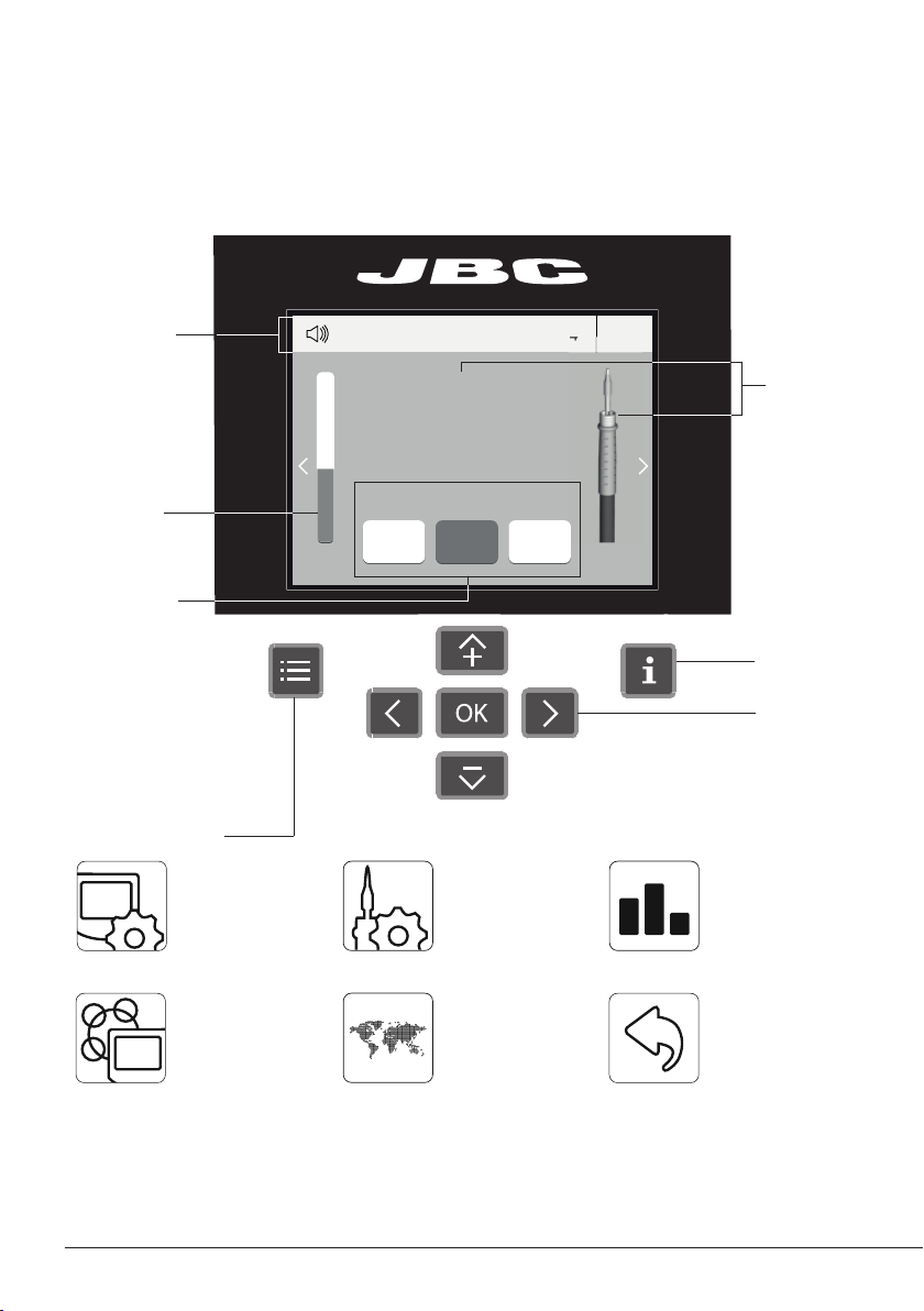
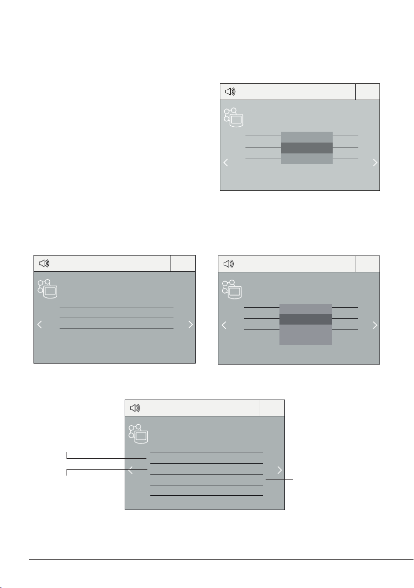
Menu Options
Station
Information
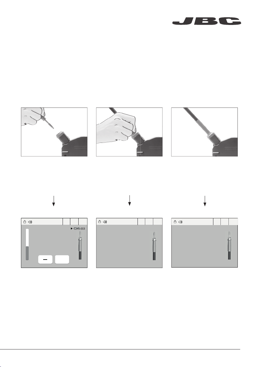
Power
indicator
Tool
in use
DDE Work Screen
Status bar
The DDE offers an intuitive user interface which provides quick access to station parameters.
Default PIN: 0105
Change
port
Displayed if
temperature
levels are
activated
Station Tools Counters
ResetLanguagePeripherals
Set the station
parameters
Set the tool
parameters
Consult / modify the
links of the peripherals
connected to the
station with the port
they are connected to.
Display the hours
worked in each cycle
It is possible to
choose the language
from a list.
Allows you to carry
out an overall station
reset restoring all the
parameters to their
default values.
Station troubleshooting available on the product page at www.jbctools.com
Troubleshooting
JBC Net
Export graphics
Insert a USB flash drive into the
USB-A connector to save your
soldering process in csv format.
Profiles
Advanced functionalities
It provides detailed graphics of tip temperature and power delivery in real time during
solder joint formation for analysis purposes. This helps you decide how to adjust your
process or which tip to use to obtain the best quality soldering.
Graphics
The first system to optimize traceability in soldering
- Get greater quality and control in your production
- Manage your whole soldering process remotely in real time
Designed to avoid thermal shock when soldering Ceramic Chip components like
MLCC, this new and unique feature allows controlling the heating ramp up rate of the
tool to gradually increase the temperature of the
component through all the phases of the soldering process. Up to 25 fully configurable
soldering profiles can be stored.
USB flash drive is connected.
Station is controlled by a PC.
Station is controlled by a robot.
System notifications
Station software update.
Press INFO to start the process.
Warning.
Press INFO for failure description.
Error.
Press INFO for failure description,
the type of error and how to proceed.
The following icons will be displayed on the screen’s status bar.
Station update
Download the JBC Update File from
www.jbctools.com/software.html
Insert the USB flash drive with the
file downloadedto the station.
Files
Update
www.jbctools.com
5