Thank you for placing your trust in our company by purcha-
sing the Weller hot air station WAD 101 / WAD 101IG.
Production was based on stringent quality requirements
which guarantee the perfect operation of the device.
1. Caution!
Please read these Operating Instructions and the attached
Safety Information carefully prior to initial operation. Failure
to observe the safety regulations results in a risk to life and
limb.
The manufacturer shall not be liable for damage resulting
from misuse of the machine or unauthorised alterations.
The Weller hot air station WAD 101 /WAD 101IG corresponds
to the EC Declaration of Conformity in accordance with the
basic safety requirements of Directives 2004/108/EC,
2006/95/EC and 2011/65/EC (RoHS).
2. Description
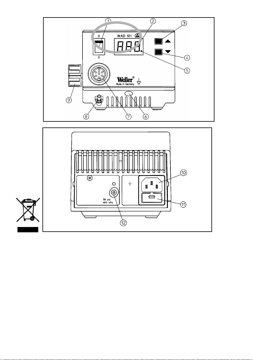
2.1 Control Unit
The WAD 101 is a hot air station that features a wide variety
of functions.
Control unit WAD 101IG
The WAD 101IG is an inert gas soldering station designed for
the operation of inert gas soldering irons WP 80IG and
WP 120IG.
As a result of the use of a microprocessor, the unit is straight-
forward and easy to use. The control electronics ensure opti-
mal adaptation of the control characteristics to different sol-
dering tools. The soldering tools themselves are detected
automatically and assigned the appropriate control parame-
ters. Excellent dynamic behaviour is made possible by the
particularly powerful 24 W heater elements. The soldering
tool is thus of universal application.
The required temperature can be set via 2 buttons
(UP/DOWN). Temperatures from 50°C - 550°C
(122°F - 999°F) are realisable with hot air soldering tools.
When a soldering iron is connected, the adjustment range is
automatically limited to max. 450°C (842°F). Required and
actual values are displayed digitally. A flashing red LED indi-
cates when the selected temperature is reached, this LED
serves as an optical regulator monitor. The continuous illumi-
nation of the LED indicates that the system is warming up.
In the case of the control unit WAD 101, air flow is controlled
by a finger switch integrated in the handle. The air flow is
controlled via a finger operated switch integrated in the
handle. The flow rate can be adjusted continuously over the
range from approx. 0-10 l/min via a control valve.
The hot air output is free of static charge.
In the case of control unit WAD 101IG, gas flow is control-
led by tool stand WDH 10T.The flow rate can be adjusted wit-
hin the 0-5 l/min range.
Various methods of equipotentially bonding the soldering iron
bit, a zero voltage switch, and the anti-static design of the
control unit and soldering tools supple ment the high stan-
dard of the unit. The possibility of connecting an external
input unit extends the functional diversity. Additional functi-
ons including timing and interlocking can be realised using
the WCB 1 and WCB 2
Input Units, available as optional extras. The extended featu-
res of the WCB 2 Input Unit include an integrated temperatu-
re measurement unit.
2.3 Soldering irons
HAP 1:
100 W hot air soldering tool with integrated finger switch.
Suitable for soldering and desoldering surface mounted com-
ponents. A wide range of nozzles makes the tool of universal
application.
The hot air tool can cannot be operated with WAD 101IG
WMP:
The Weller Micro Soldering Iron WMP is suitable for
processing SMD electronics due to its manageable design.
The short distance between grip and soldering tip makes
ergonomic handling of the 65 W soldering iron possible when
carrying out very fine soldering tasks.
MPR 80:
The Weller Peritronic MPR 80 soldering iron has an adjusta-
ble workingangle of 40° to enable an individually ergonomic
soldering process.The 80-watt power and slim design makes
this soldering iron suitable for fine soldering work.
WTA 50:
The unsoldering tweezers WTA 50 were specially designed
for unsoldering SMD components. Two heating elements
(2 x 25 watts), each with its own temperature sensor, ensure
constant temperatures at both ends.
LR 82:
High-performance 80 watt soldering iron for soldering work
with high heat requirements. The soldering tip is attached by
a bayonet catch to ensure correct position when using
different tips.
English
17