2
Contents
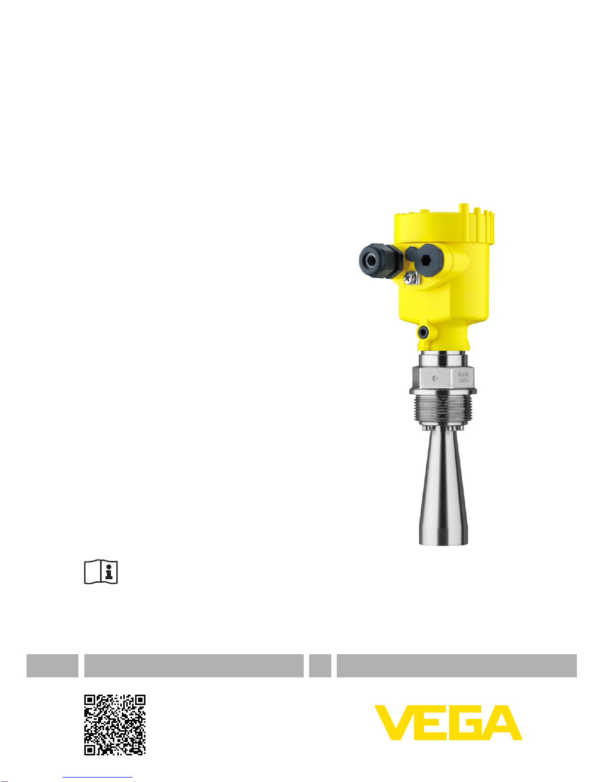
VEGAPULS 62 • 4 … 20 mA/HART - two-wire
41718-EN-140209
Contents
1 About this document
1.1 Function ........................................................................................................................... 4
1.2 Target group..................................................................................................................... 4
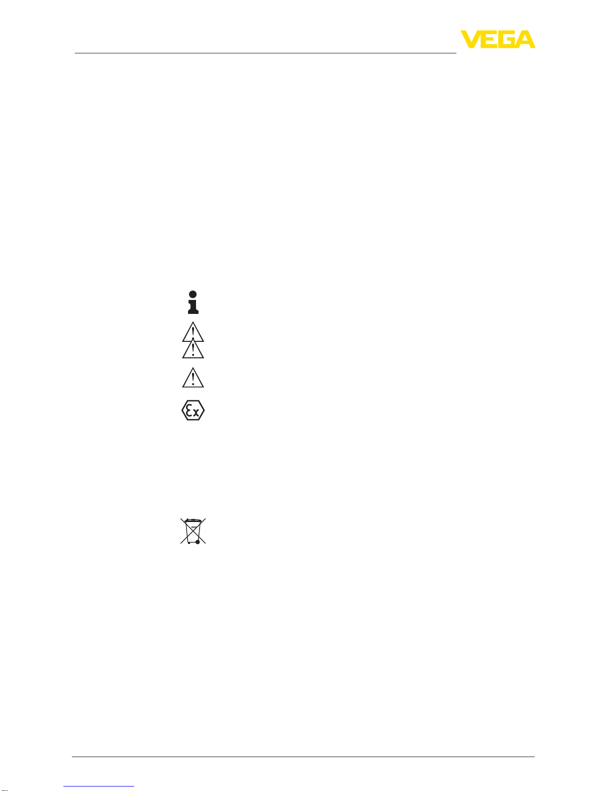
1.3 Symbolism used............................................................................................................... 4
2 For your safety
2.1 Authorised personnel ....................................................................................................... 5
2.2 Appropriate use................................................................................................................ 5
2.3 Warning about incorrect use............................................................................................. 5
2.4 General safety instructions............................................................................................... 5
2.5 CE conformity................................................................................................................... 6
2.6 NAMUR recommendations .............................................................................................. 6
2.7 Radio license for Europe .................................................................................................. 6
2.8 Radio license for USA/Canada......................................................................................... 7
2.9 Environmental instructions ............................................................................................... 7
3 Product description
3.1 Conguration.................................................................................................................... 8
3.2 Principle of operation........................................................................................................ 9
3.3 Packaging, transport and storage................................................................................... 10
3.4 Accessories and replacement parts ............................................................................... 10
4 Mounting
4.1 General instructions ....................................................................................................... 13
4.2 Mounting preparations - Horn antenna........................................................................... 13
4.3 Mounting instructions ..................................................................................................... 14
5 Connecting to power supply
5.1 Preparing the connection ............................................................................................... 26
5.2 Connecting..................................................................................................................... 27
5.3 Wiring plan, single chamber housing.............................................................................. 28
5.4 Wiring plan, double chamber housing ............................................................................ 29
5.5 Wiring plan, double chamber housing Ex dia ................................................................ 31
5.6 Double chamber housing with DIS-ADAPT .................................................................... 32
5.7 Wiring plan - version IP 66/IP 68, 1 bar........................................................................... 33
5.8 Switch-on phase............................................................................................................. 33
6 Set up with the display and adjustment module
6.1 Insert display and adjustment module............................................................................ 34
6.2 Adjustment system......................................................................................................... 35
6.3 Parameter adjustment .................................................................................................... 36
6.4 Saving the parameter adjustment data........................................................................... 50
7 Setup with PACTware
7.1 Connect the PC.............................................................................................................. 51
7.2 Parameter adjustment .................................................................................................... 52
7.3 Saving the parameter adjustment data........................................................................... 53
8 Set up with other systems
8.1 DD adjustment programs ............................................................................................... 54
8.2 Field Communicator 375, 475 ........................................................................................ 54
9 Diagnosis, asset management and service