3.2Principle of operation
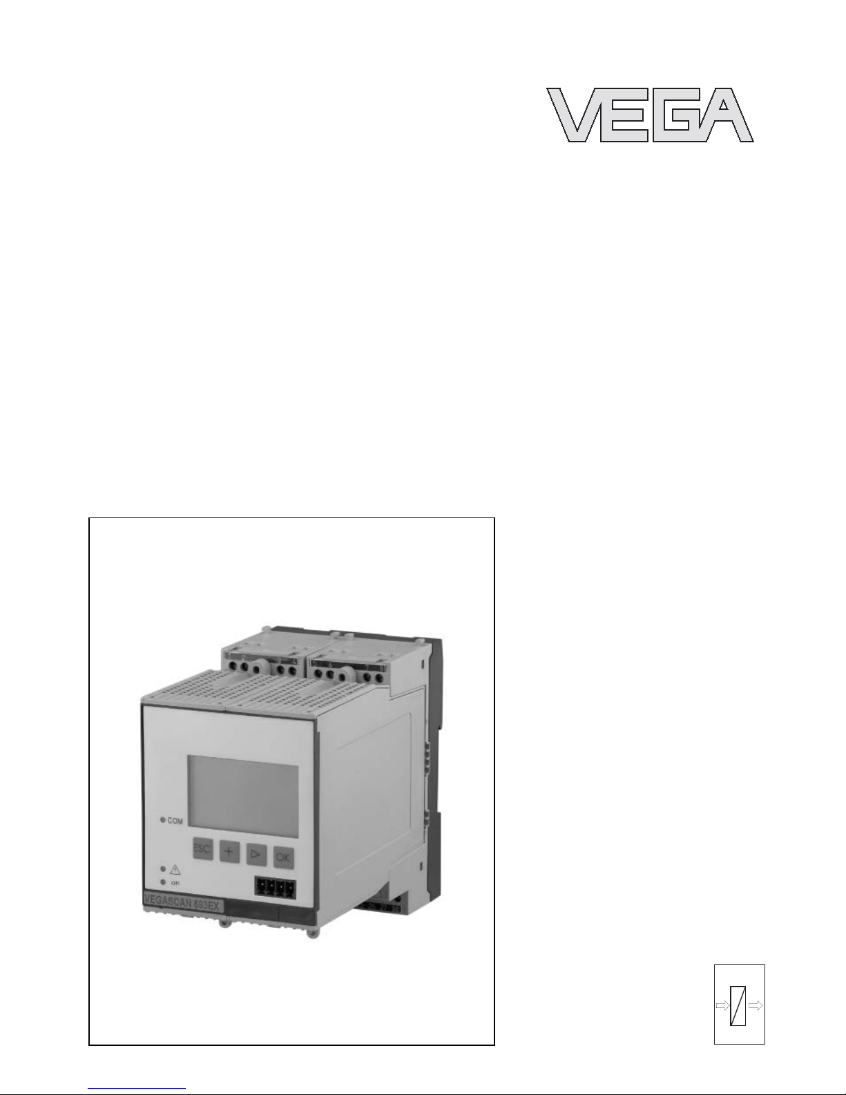
VEGASCAN 693 is a universal signal conditioning instrument
for a number of applications such as level,gauge and process
pressure measurement.At the same time,it can serve as
power supply unit for connected sensors.VEGASCAN 693 is
designed for connection of 15 independent VEGA HART
sensors (5with Ex applications). Hence 15 (5with Ex)
independent measurements can be carried out.
The measured values can be retrieved through one of the
integrated interfaces (RS232/Ethernet)via modem or network
and displayed with the web browser or Visual VEGA.
Furthermore it is possible to transmit measured values or
messages by e-mail.The use of VEGASCAN 693 is
particularly suitable of stocktaking,VMI (Vendor Managed
Inventory)and remote enquiry.
VEGASCAN 693 signal conditioning instrument can power the
connected sensors and also evaluate their measuring signals.
The requested parameter is indicated in the display and,in
addition,outputted to the integrated interface and the web
server for further processing.On request,the measured values
can be sent event or time-controlled via e-mail to different
addressees.
Wide-range power supply unit with 20 …253 VAC/DC for
world-wide use.
You can find detailed information on the power supply in the
"Technical data"in the "Supplement".
3.3Adjustment
VEGASCAN 693 can be adjusted with the following adjust-
ment media:
lthe integrated indicating and adjustment unit
lan adjustment software acc.to FDT/DTM standard,e.g.
PACTware™and a Windows PC
The entered parameters are generally saved in VEGASCAN
693,when operated with PACTware™optionally also on the
PC.
Information:
When using PACTware™and corresponding VEGA DTM,
additional settings can be carried out which are not or only
partly possible with the integrated indicating and adjustment
Area of application
Physical principle
Supply
8VEGASCAN 693 -15-channel HART signal conditioning instrument
Product description
29252-EN-060513