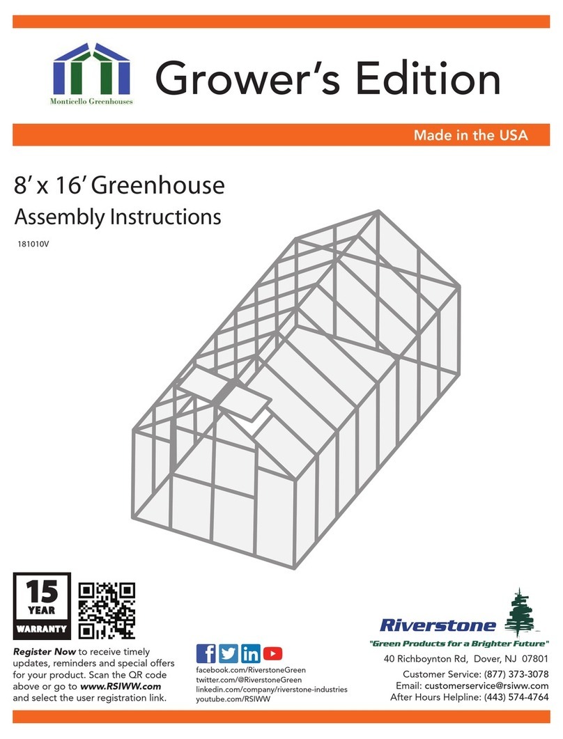
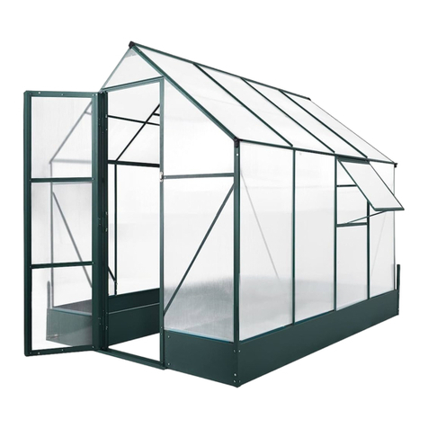
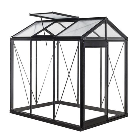
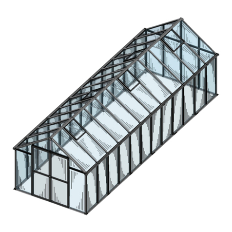
Velcom CAMELLIA R User manual

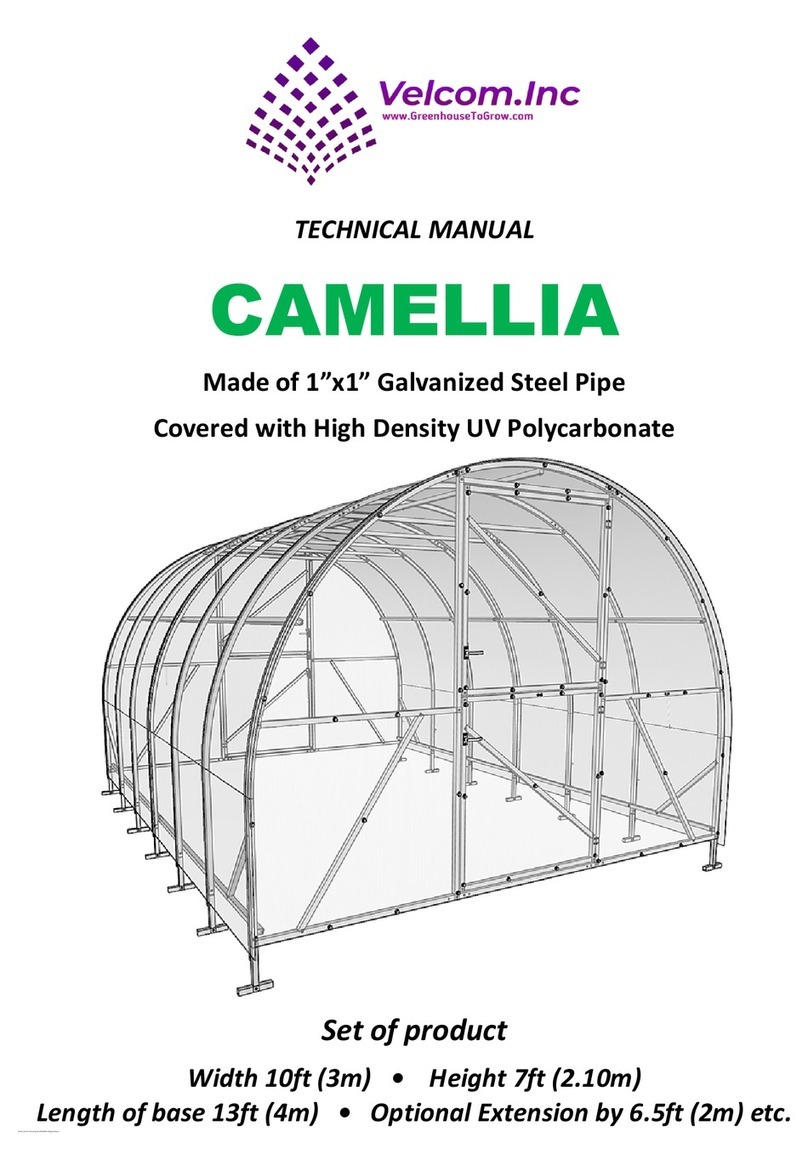
TECHNICAL MANUAL
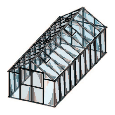
CAMELLIA R
Made from 1” x 1” galvanized steel pipe
Set of product
Width 10ft •Height 7ft
Length of 19.5ft •Extension 6.5ft etc.

- 2 -
PRODUCT COMPLETE SET PARTS
uuuuProduct
No.
Part name
Q-ty
BASE
Q-ty
EXTEN.
Denotation
1
End face half-arc, left-hand, 2535mm
2
-
2
End face half-arc, right-hand,
2355mm
2
-
3
End face lintel, top, 960mm
2
-
4
Door way post, left-hand,
2020mm
2
-
5
Door way post, right-hand,
2020mm
2
-
6
End face transverse member, left-
hand, middle, 990mm
2
-
7
End face transverse member, right-
hand, middle, 990mm
2
-
8
End face diagonal, left-hand,
1200mm
2
-
9
End face diagonal, right-hand,
1200mm
2
-
10
End face arc extension, 800mm
4
-

- 3 -
11
The left-hand part of the end face
bottom-end transverse member,
1050mm
2
-
12
Middle part of the end face bottom-
end transverse member, 900mm
2
-
13
The right-hand part of the end face
bottom-end transverse member,
1050mm
2
-
14
Intermediary arch half-arc, left-hand ,
2535mm
5
3
15
Intermediary arch half-arc, right-hand
, 2355mm
5
3
16
Transverse enhancer of the
intermediate arch, 1500mm
5
3
17
Arc Extension of intermediate arch,
800mm
10
6
18
Door lintel, top,
905mm
2
-
19
Door lintel, middle,905mm
2
-
20
Door diagonal,
1425mm
2
-
21
Door lintel, bottom-end,
905mm
2
-
22
Door post, left-hand ,
1780mm
2
-
23
Door post, right-hand ,1780mm
2
-
24
Air gate lintel, top,
850mm
2
-
25
Air gate lintel, bottom-end,
850mm
2
-
26
Air gate post, left-hand ,
470mm
2
-
27
Air gate post, right-hand , 470mm
2
-
28
Air gate jib-stick,
150mm
2
-
29
Radius connection insert (inserted
into the half-arc No.2)
7
3
30
Radius connection insert (inserted
into the transverse member No.12)
4
-
31
U-shaped grouser, 150mm
14
6
32
Longitudinal starter stringer,
2012mm
5
-
33
Longitudinal stringer with X-crimp,
2068mm
5
5
34
Lateral diagonal rod, 600mm
4
-
35
Metal tie band for Polycarbonate ,
6150mm
7
3
36
Bolt М6х60mm
35
15
37
Washer М6
49
21

- 4 -
38
Nut М6
35
15
39
Screw М4х35 mm
33
3
40
Nut М4
33
3
41
Self-tapping screw 4,2х19mm
390
66
42
Thermal-washer with cover cap
90
-
43
Door/Air gate hand lever:
Hand lever –1 pcs; shield–1 pcs;
Locking point –1pcs ; screw М5 –
2pcs.; nut М5 – 2 pcs.
4
-
44
Peg stay, 100mm
2
-
45
Door hinge
8
-
46
Door stop plate, 100mm
2
-
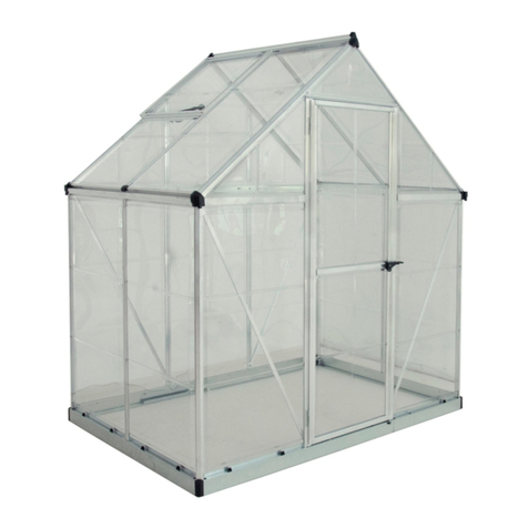
1. PRODUCT DESCRIPTION
Greenhouse CAMELLIA R is designed to create an optimal microclimate for
growing vegetables, flowers and seedlings in the smallholding. The frame parts are
made of steel galvanized pipe with a square cross-section of 25 x 25 mm.
The greenhouse is intended to be covered with multiwall UV protected
polycarbonate.
The end faces and the frame intermediate arches are connected by five
longitudinal stringers. Transverse arch enhalf-arcrs are provided, 1 per an arch, to
achieve the strength of the entire frame. To exclude the slope of the frame end faces
under wind loads, end face diagonal rods are also provided, 2 pieces per each end
face.
Elements necessary for the assembly (self-tapping screws, bolts, nuts, fittings) are
supplied in boxes. To fasten the multiwall polycarbonate to the frame of the
greenhouse, steel galvanized tie bands with tensioning system are provided: one tie
band per each arc and end faces.

- 5 -
2. END FACES ASSEMBLY
2.1. Joint the left-hand end face
half-arc No.1 and the right-hand end
face half-arc No. 2 (half-arcs of first
end face are marked with "1A" and "2A";
half-arcs of the second end face are
marked with "1B" and "2B"). Fasten the
connection with self-tapping screws
No. 41 (2 on each side). The assembly
will result in an end face arch.
2.2. Insert the extensions No.10 into
the end faces of the arch described in
cl. 2.1 on the left and the right, by
knocking them in until they are firmly
fastened (with a mallet or hammer
through a block), fasten them with
self-tapping screws No.41 (4 pcs. per
each extension).
Fasten the grouser’s No. 31 with self-tapping screws No. 41
(2 pcs. per each ground grouser).
2.3. Fasten the left-hand doorway post No.4 and right-hand doorway post No.5
(with holes for hinges) to the top of the end face arch with self-tapping screws
No.41 installed in the pre-designated locations:

- 6 -
2.4. Fasten the left-hand No.11 and right-hand No.13 parts of the bottom-end
transverse part to the No.10 extensions with No.41 self-tapping screws:
2.5. Connect the middle part No.12 of the bottom-end transverse part to the left-
hand and right-hand parts, with simultaneous attachment of the left-hand No.4 and
right-hand No.5 doorway posts to them. Secure the connections with No.41 self-
tapping screws:
2.6. Install the end face top lintel No.3 between the door posts No.4 and No.5,
fasten them with self-tapping screws.

- 7 -
2.7. Install the left-hand
No.6 and the right-hand No.7
end face transverse parts and
fasten them with self-tapping
screws No.41:
2.8. Install the left-hand No.8 and the right-hand No.9 end face diagonals and
fasten them with self-tapping screws No.41:
2.13. Fasten stop plate No.46
with self-tapping screws No.41 to
the corner of doorway on the inside:

- 8 -
2.9. Using parts Nos.18-23 and self-tapping screws No.41 assemble the doors.
Use an angle piece to ensure correct geometry when assembling. The doorpost No.23
with hinge holes should be on the right-hand side:
2.10.Using parts Nos. 24-28 and self-tapping screws No.41 assemble the air
gates. Use an angle piece to ensure correct geometry when assembling. The air gate
post No.27 with hinge holes should be on the right-hand side:

- 9 -
2.11. Insert the air gate in the door and secure it with two hinges No.45 using
screws No.39 and nuts No.40. Fasten the upper hinge of the door to the upper hinge
of the air gate, and fasten the lower hinge of the door to the lower hinge of the air
gate:
2.12. Insert the door into the end face opening, secure with screws No.39 and
nuts No.40.
3. INTERMEDIATE ARCHES ASSEMBLY
3.1. According to the instructions provided in cl. 2.1, connect the left-hand No.14
and right-hand No.15 half-arc of the intermediate arch. Fasten the connection with
four self-tapping screws No.41 (2 on each side).
3.2. Insert the extensions No.17 into the end faces of the arch of cl. 3.1 on the left
and right as was indicated in cl. 2.2, knocking them in until they are firmly fastened
(with a mallet or hammer through a block), fasten them with self-tapping screws
No.41 (4 pieces per each extension). Fasten the grousers No.31 with self-tapping
screws No. 41 (2 pcs. per each grouser).
3.3. Install the arch enhancer No.16, Fasten it with self-tapping screws No. 41:

- 10 -
4. FRAME ASSEMBLY
End face “A” Intermediate arch End face “B”
4.1. Fasten starter stringers No.32 to the “A" end face of the inside of the arch
with bolts, washers and nuts Nos.36-38 inserted into the drilled holes.
4.2. Fasten two intermediate arches to the starter stringers using bolts, washers
and nuts Nos.36-38.
4.3. Inset stringers No.33 with X-shaped crimp into starter stringers No.32.
4.4. Connect intermediate arches to assembled details with bolts, washers and
nuts No.36-38 inserted into the drilled holes.
4.5. Fasten the end face “B” (for greenhouse of 4 m length) with bolts, washers
and nuts Nos.36-38.
4.6. To extend the greenhouse by 2 m, use extension kits consisting of five X-
shaped crimp stringers No.33 and three intermediate arches.
4.7 Install the stringer No.34 between the end face and the bottom-end
longitudinal stringer, aligning the end face with the angle piece. Secure with self-
tapping screws No. 41:

- 11 -
6. FASTENING OF MULTIWALL POLYCARBONATE (PC) TO THE END FACES
6.1. Place a 2100 mm x 6000 mm PC sheet face up on a flat surface.
6.2 Cut the sheet lengthwise into two equal pieces of 1050 mm x 6000 mm. Cut
the sheets into pieces according to the diagram:
мм=mm
6.3. Put the part 1 of PC to the end face door by aligning the bottom edge of PC
along the bottom lintel of the end face. Fasten part 1 with self-tapping screws No.41
through thermal washers No.42 according to the scheme of polycarbonate fastening.
6.4 Put the part 3 of PC to the left-hand side of the end face, and the part 4 - to
the right-hand side of the end face, having aligned the bottom edge of PC on the
bottom lintel of the end face. Fasten the parts 3 and 4 with self-tapping screws No.41
through the thermal washers No.42 according to the scheme.
Mount parts 2-5-6 on the second end face in the same way.
6.5. Cut the protruding PC on the radius of the end face arch. Make cuts along the
vertical and horizontal edges of the doors and air gates of both ends.

- 12 -
Scheme of polycarbonate fastening on the end faces.
6.6. Fasten the peg stay No. 44 on the right-hand middle lintel of the end face
with self-tapping screws No. 41, and the mating hinge on the door so that the peg
stay fixes the door in the open position.
6.7 Insert the hand lever No.43 into the Ø12 holes on the doors and on the air-
gates, by drilling the corresponding holes in the polycarbonate.
On the back side put on the locking point and the shield, fastening them with
screws and nuts M5:
6.8. Mount hand levers of air-gates in the same way.

- 13 -
7. FASTENING OF MULTIWALL POLYCARBONATE (PC) TO THE ROOF
WARNING!
Before installation of PC on the roof make sure that the geometry of the frame is
correct.
The diagonal distance between the corners of the frame should be equal.
The longitudinal stringers must be plane, without bends and distortions.
It is necessary to remove the wrapping film from both sides of the sheet.
The front (facing the sun) side of the multiwall polycarbonate is marked by the
manufacturer with a special symbol (color stripe, sticker or other).
MUultiwall polycarbonate lines must be placed along the arches of the frame of the
greenhouse.
7.1. Mount the end sheets of tthePC
(from the end faces) at first. Install the PC
sheets so that they protrude (hang down)
50 mm beyond the edge of the end face.
7.2. Press the first sheet of PC with
tightening tape No. 35 (item 1) and fix one end of the tape with a self-tapping screw
No. 41 to the leg of the arch, below the edge of the polycarbonate.
7.3. Bend the tape at the place where the two holes are punched 5 cm apart
(item 2) so that the holes are opposite each other.
7.4 Insert the screw No.39 with two washers No.37 into the holes and tighten the
nut No.40.
7.5 Tighten the tie band by hand and fix the second end to the opposite leg of the
arch (item 3) with self-tapping screw No.41.
7.6. Center the tie band along the arch. Tighten the tie band with screw No.39
and nut No.40 through washers No.37 (Figure 12-2). The tie band should hold the
sheet tight against the arch.

- 14 -
7.7. Mount with overlapping joint the
intermediate PC sheet to the previous
sheet and tighten with the tie bands.
After installing all the sheets, check the
correct positioning of the PC sheets, the
parallel alignment of PC lines to the
arches, the position and the tension of
the tie bands.
At least once a year, check the tension of the tie bands.
11. GREENHOUSE INSTALLATION
Before starting operations, carefully adjust the site on which the greenhouse will
be installed.
Dig holes or trenches of sufficient length and width under the legs equipped with
grousers. Position the assembled greenhouse so that the bottom longitudinal
stringers are on the same level with the ground and the legs are deepened into the
ground. Backfill the legs with soil and apply tamping to the ground.
When lowering the greenhouse into the trench or holes, make sure that there is
no longitudinal misalignment of the frame and that the tie bands are not displaced
from the arches. After tamping the ground, make sure that the tie bands are not
offset to the sides and are along the arches. Correct if necessary.
A wooden frame or concrete or brick foundation can be used to enhance the
greenhouse.
Warning!
The greenhouse has a surface exposed to the wind. It is forbidden to leave the
greenhouse unfasten on the ground. Additional fastening to the ground with available
materials (rod, rebar, etc.) is necessary if the greenhouse is installed in windy area.
Do not install the greenhouse close (less than 2 meters) to buildings, safety
enclosure, fences.
The area on which the greenhouse is installed should be flat, without significant
differences in the level of the ground.

- 15 -
WARRANTEE OBLIGATIONS
1. The manufacturer guarantees that the greenhouse frame (hereinafter referred to as
the product) is new, fully equipped, and free from manufacturing defects.
2. The manufacturer is responsible for the completeness of the product.
3. The manufacturer is responsible for the assembly of the product according to the
instructions.
4. The warranty period for this product is twelve (12) months from the date of sale to
the purchaser through the retail network.
5. The warranty covers any manufacturing and material defects.
6. The warranty does not cover damage caused by corrosion of the product design
elements, snow and wind loads (more than 10 m/s).
7. The warranty is terminated in the following cases:
- failure to comply with the assembly and installation instructions;
- failure to comply with the requirements for greenhouse operation;
- in case of use of the greenhouse for purposes other than those for which it is
intended;
- in the event of force majeure (natural disasters);
- in the absence of the product datasheet.
8. The warranty does not cover cellular polycarbonate.
Warning!
In winter, in order to prevent deformation of the greenhouse parts under the exposure of
snow and wind loads, it is necessary to remove all sheets of multiwall polycarbonate from the
arched part of the greenhouse (the greenhouse roof) by removing tie bands. The advantage of
sheets removing for winter is that the snow gets inside the greenhouse, which during melting
enriches the soil with useful minerals and protects it from desalinization. An open roof over the
winter prevents pests from crawling into the warm greenhouse with the onset of cold weather
and eating the young shoots in the spring.
If it is not possible to dismantle the sheets, the arches should be enhanced from the inside
with T-shaped wooden supports (from a wooden bar of at least 50x50 section), by placing them
inside the greenhouse - one bar for each arch. Wooden supports are not included in the kit,
make your own. Depending on the climatic conditions and/or location of the greenhouse, it is
up to the purchaser to assess the possible snow load and, if necessary, to provide supports or
remove snow from the frame.
Failure to comply with the requirements above shall be the reason for rejection of product
warranty service.
Do not install the greenhouse closer than 2 meters to buildings, safety enclosures and
fences. If the greenhouse is installed in windy area, ensure its firmly fastening to the ground
using appropriate means (rod, rebar, etc.). Do not subject the greenhouse frame to excessive
mechanical stresses. Do not modify the construction of the product yourself.

- 16 -
Thank you for choosing the CAMELLIA R greenhouse
which will serve you for decades under proper usage!
Due to the continuous improvement of the products
the manufacturer reserves the right to make changes
in the design without prior notice to the consumer.
The products are not subject to mandatory certification.
Distributed by VELCOM, INC
200 Parkway Dr
Lincolnshare, IL 60069
Table of contents
Other Velcom Greenhouse Kit manuals