Velcom MAGNOLIA User manual

TECHNICAL MANUAL
MAGNOLIA
Made of 1”x1” Galvanized Steel Pipe
Covered with High Density UV Polycarbonate
Set of product
Width 10ft (3m) • Height 7.1ft (2.15m)
Length of base 13ft (4m) • Optional Extension by 6.5ft (2m) etc.
Thank you for choosing the MAGNOLIA greenhouse
Which will serve you for decades under proper usage !
Due to the continuous improvement of the products
the manufacturer reserves the right to make changes
in the design without prior notice to the consumer.
The products are not subject to mandatory certification.
Distributed by VELCOM, INC
847-507-8448
224-254-3993
Thank you for cho osing the M AGN O LI A g reenhous e
Whic h wi ll serve you for deca des unde r pro pe r usa ge !

TECHNICAL CERTIFICATE of GREENHOUSE “MAGNOLIA”
DISCRIPTION
The greenhouse “MAGNOLIA” is designed to create the climate, which is productive to grow
horticultural crops on the garden plots.
The length of the greenhouse is 13’ (4m) width is 10’ (3m) and height is 7.1’ (2.15m) with ability
to extend length by 6.5’ (2m) up to 32.5’ (10m) the surface of the protected soil is 130 ft2.
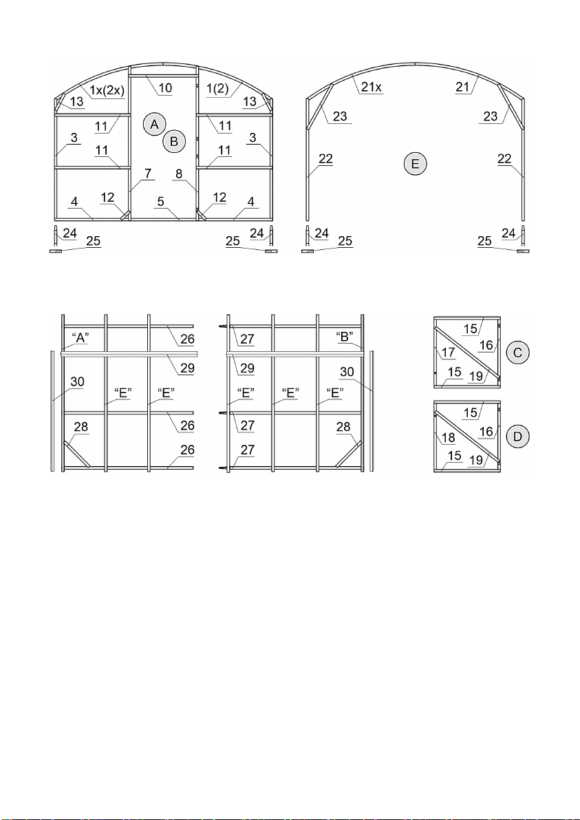
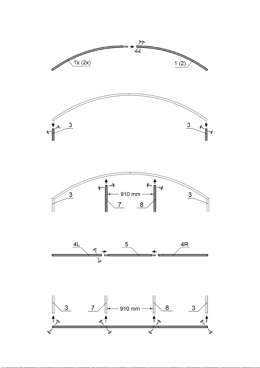
The frame of the greenhouse is made of square galvanized pipe 1”x1” and it is assembled with
the studs, screws, nuts. The kit includes everything you need to assemble the frame and fasten
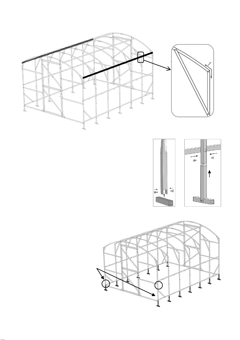
the covering. The foundation of the greenhouse is not obligatory to install but recommended.
The greenhouse is fixed on the ground by digging in to the ground special frame endings. For
fixing cellular polycarbonate to the greenhouse roof, galvanized steel strapping tape is used.
The greenhouse covering is completed on buyer’s request. To cover the greenhouse you need
a greenhouse frame is designed for covering with cellular polycarbonate 4 mm thick with a High
Density of at least 0.7 kg / m2. The greenhouse has two doors, one on each end and two vents.
Assembly instructions and operating rules
The greenhouse should be assembled and installed on the ground according the instruction.
The buyer should control the assembly quality if it is made by third person.
Self-tapping screws of mount structure should be tightened to contact the flat head of the
screw with the covering surface and hold it to the frame, but do not allow the extra rundown of
the screws.
Avoid installing the greenhouse closely to the buildings and trees. The melting snow or ice is a
potential hazard. The recommended distance is minimum 7ft.
The greenhouse is designed to endure the wind of less than 50mph.
There is no need to skin the greenhouse during the winter time for the greater parts of the
regions of Canada and USA. If the greenhouse in not looked after during winter, the customer
should determine the possible snow load or to skin the covering.
The limit snow load for the frame takes place when the weight of the snow blanket is
240 kg/m2 (120Lb/ft2) of horizontal ground surface. This limit snow load requires characteristic
snow load of the North snow region (according the classification of construction rules and
regulations “Loads and actions”).
For assembly, you will need: a 10mm wrench, a screwdriver with a PH2 attachment, a sharp
knife, a carpenter square, a level, a 7-10 m tape measure, a ladder and protective gloves.
*Metric measuring tape needed! Cm/mm

- 2 -
1. LIST OF ACCESSORIES
№Part name BASE
13’L
INSERT
+6.5’L
(optional)
Image
(could be different
from the actual configuration)
1 End-Face half-arch, right -hand "A" 1 -
1x
End-Face half-arch, left-hand, "A"
(with X-crimping)
1 -
2 End-Face half-arch, right -hand "B" 1 -
2x
End-face half-arch, left-hand, "B"
(with X-crimping)
1 -
3 End-face post, side, 1670 мм 4 -
4
Lower lintel, side for End-face
(4L- left,4R - right), 1045мм
4 -
5
Lower lintel, middle for End-face ,
910мм (with X-crimping)
2 -
7
Left door-way post, 2115 мм
2
-
8
Right door-way post, 2115 мм (with
holes for hinge)
2 -
10 Top lintel, middle for End-face, 960мм 2 -
11
Middle lintel, side for End-face,
1040мм
8 -
12
Jib-stick, small support, 150мм
4
-
13
Jib-stick, middle support, 250мм
4
-
15
Air gate lintel, top/bottom "C", "D",
902mm
8 -
16
Air gate right post "C", "D",
960 mm (with hinge holes)
4 -
17
Air gate left post, "C", 960mm (Hole
for Handle Bottom)
2 -
18
Air gate left post, "D", 960mm (Hole
for handle from above)
2 -
19
Diagonal air gate support "C", "D",
1100 mm
4 -
21
Intermediate arch, half-arc,
right-hand “E” ”
5 3
21x
Intermediate arch, half-arch, left-hand
“E” (with X-insert)
5 3
22
Side post for intermediate arch, “E”,
1670 мм
10 6
23
Intermediate arch, top diagonal
support “E”, 700мм
10 6
24
Anchor post, 250мм
14
6
25 Anchor grouser, 150мм 14 6

- 3 -
№Part name BASE
13’L
INSERT
+6.5’L
(optional)
Image
(could be different
from the actual configuration)
26
Connecting stringer starter,
2012 mm
6 -
27
Connecting stringer
With X-crimping, 2068 mm
6 6
28 Side diagonal support, 600 мм 4 -
29
Outside corner roof molding,
120° / 2025 мм
8 4
30 Outside corner molding, 90° / 1670 мм 8 4
31 Steel Tie band,, 20x3400мм 7 3
40 Bolt M6x60mm 42 18
41 Nut M6. 42 18
42 Washer M6. 56 24
43 Bolt m4x35 mm 40 3
44 Nut M4. 40 3
45
Self-Tapping screw 4,2х16мм
(for assembling frame elements)
420 86
46
Self-Tapping screw 4.2x19mm
(for fastening polycarbonate)
190 30
47
Thermo-pad with cap
(for fastening polycarbonate)
190 30
48 Set of door knob
(handle, pad, rigl) 4 -
49 Door holder, 200 мм 2 -
50 Door hinge 8 -
51 Door latch 2 -
52 Stubborn plate for door, 100mm 2 -

- 4 -
2. ASSEMBLY DIAGRAM “MAGNOLIA” PRODUCT
Fig.1 End-Face "A" and “B" Fig.2 Intermediate arch "E"
Fig.3 Assembling frame (side view) Fig.4 Air gate Doors "C", "D"
3. Assembling End-Face "A" and "B" Fig.1
Attention!
Places of fastening parts are indented and circled with a marker. Polycarbonate
mounting places are indented.
To comply with the correct geometry, the assembly must be made on a flat surface.
Before assembly, sort and decompose the details of the ends, doors and intermediate
arches according to the scheme and the list of components.
For convenience and to accelerate assembly, the fastening of parts by self-drawers
can be made on one side of the assembly element, then gently flip the design and
secure the screws on the other side.

- 5 -
3.1. Connect the left 1x and right 1half-arch of the end-face "A". Secure the
connection from two sides by four self-tapping screws 45 (16 mm).
Similarly, connecting left 2x and right 2, and assembling the end-face "B".
3.2. Secure the post 3 to the Arch ends by self-tapping screws 45.
3.2. Secure the Left post 7to the arc and the right post 8of the doorway stands with
self-tapping screws 45 on both sides. The distance between posts 7-8 is 910mm
3.3 Connect the Lower lintels 4(4L-4R) with lintel 5, fasten with screws 45 on both
sides by tying 2screws on 1compound:
3.4. Fasten the collected item from clause 3.3. Door-way posts 3-7-8 at the
bottom with self-tapping screws 45 on both sides, 2 self-compound self-press.
The distance between the door-way posts 7-8 should be 910 mm:

- 6 -
3.5. Install the Top lintel
10 between the posts 7-8 at a
distance of 1950mm from the
lower lintel, fasten with the
screws 45:
3.6. Set four Middle lintels 11
between the doorway posts
7-8 and side post 3, secure
with the screws 45:
3.7. In a door-way, Insert
carpenters Square and make
sure it is 90°. Fasten the Jib-sticks 12 with screws 45 to posts 7-8
3.8. Fasten the Jib-sticks
13 with screws 45 to post 3
and top arch.
3.9. Fasten the Stubborn
plate for door 52 with screws
45 In the upper left corner of
the doorway from the inside
(to prevent the door opening
inside).

- 7 -
Assembling Air gate Doors "C", "D" Fig.4
3.10. Using the details 15-16-17-18-19, assemble with self-tapping screws 45 the
top door "C" and the lower door "D" . Right post 16 on door "C","D", 960mm (with
hinge holes) must be right, and 17(18)with hole for handle must be left.
Hole for the handle in the top door "C" should be located below, and in the
bottom door "D" - from above.
Insert carpenters Square and make sure it is 90°. Insert and fasten the diagonal
air gate door support 19 with screws 45:
Doors “C”, “D”
3.11. Insert the doors "C", "D" in the opening of the End-Face "A" and "B", secure
with hinge 50, bolts 43 and nuts 44:

- 8 -
4. Assembling intermediate arches Fig.2
Assemble the intermediate arches "E" using the half-arc 21x-21, Side posts for
intermediate arch 22, install top diagonal support 23 with the self-tapping screws 45.
To comply with the correct
geometry of the arches, use
the assembled end as a
template, setting it the details
for the assembly of the arch.
5. Assembling the FRAME For the frame assembly scheme, Fig.3
5.1. Using bolts 40, washers 41 and nuts 42 connect the Front end "A" with six
starting stringers 26 through the holes drilled in the side posts.
5.2. Next fasten using bolts 40 starter stringers with two intermediate arches “E”.
5.3. Insert 27 X-Crimp stringers into 26 starter stringers.
5.4. Fasten using bolts 40 the stringers 27 with intermediate arches “E” through
the drilled holes.
5.5. Fasten with bolts 40 to the End Face “B” (for base frame 13’ (4 m) long).
To EXTEND the frame by 6.5’ (2m), use sets of six 27 X-crimp stringers and three
intermediate arches (Optional possible extension length is 19.5’L , 26’L etc.).
5.6. Install the side diagonal support, 600 мм
28 between the side posts of the end face 3
and the lower longitudinal stringers 26-27. Fix
the braces with self-tapping screws 45,
preliminarily setting an angle of 90 degree
between the end face and the stringer using a
Carpenter square.

- 9 -
5.7. Install the Outside corner roof molding 29 (120° / 2025mm) in the joints of
the pillars and the roof arch, fix them from above with self-tapping screws 45.
5.8. Connect the Anchor grouser 25 (150mm)with
Anchor post 24 (250mm)using self-tapping screws 45
so that you get T-shaped Anchor-legs.
5.9. Insert the Anchor-legs into the side post from
below until it stops, fix with two self-tapping screws
45.
5.10. Install the all Anchor-legs in all other racks in
the same way.
Attention!
For mounting Anchor-legs
into the end posts, you must first
unscrew the self-tapping screws
connecting the post and the
lower crossbar, mount the leg,
screw the self-tapping screws
back.

- 10 -
5. INSTALLATION OF CELLULAR POLYCARBONATE (CP) TO THE ENDS
The required number of sheets and cutting patterns for cellular polycarbonate are
given at the end of the instructions Annex 1.
The greenhouse frame is designed to be covered with
Cellular polycarbonate 4mm thick
Attention! When installing the Polycarbonate, it is important that the lines of
the joint venture cells are located vertically (from top to bottom). That is necessary
to remove the wrapping film from both sides of the sheet. The front (facing the sun)
side of cellular polycarbonate is indicated by the manufacturer with a corresponding
symbol (colored stripe, sticker, or in another way).
5.1. Cut the polycarbonate into pieces according to the cutting pattern Annex 1.
5.2. Attach part “A” of Polycarbonate to the end door, aligning the bottom edge
of the polycarbonate with the bottom lintel of the end. Fix part “A” with self-tapping
screws 46 through thermo washers 47 according to the polycarbonate fastening
scheme (see below).
5.3. Attach part “B” of Polycarbonate to the left side of the End-Face "A" and “B"
and part “C”to the right side of the End-Face "A" and “B", aligning the lower edge of
the joint venture with the lower lintel of the End-Face. Fix parts “B” and “C” with self-
tapping screws 46 (19 mm) through thermo washers 47 according to the scheme for
attaching polycarbonate to the End-Face (see below).
5.4. Mount the polycarbonate on the Back-end in the same way.
5.5. Cut off the protruding edges of the Polycarbonate along the outer edge of
the frame.
5.6. Cut through the slots of the doors and vents in parts “A”.
Layout of polycarbonate sheets at the Front/Back End

- 11 -
The scheme of fixing cellular polycarbonate to the end-face and doors
5.7. Fasten hook 49 with self-tapping screws 45 to the right upper crosspiece of
the end, the counter loop of the hook on the diagonal of the upper door so that the
hook fixes the door in the open position (see the picture above).
5.8. Insert the handles from kit 48 into the Ø12 holes on the door, having
previously drilled the corresponding holes in the polycarbonate. On the reverse side,
put on the deadbolt and pad, fix the handle and pad with self-tapping screws 45.
5.9. Fasten the door latch 51 with self-tapping screws
45 from the inside between the lower and upper Air-doors
so that the doors can be fixed to each other.
To do this, it will be necessary to unscrew the self-
tapping screw in the corner of the door, mount the latch,
and screw the self-tapping screw back.

- 12 -
6. MOUNTING OF CELLULAR POLYCARBONATE ON SIDE WALLS
Parts “E” with dimensions 2100x1670mm are used for side walls mounting. Annex 1.
6.1. Start mounting the Polycarbonate sheets “E” on the sides from the ends.
Attach a sheet of polycarbonate to the wall of the frame, aligning the top of the sheet
in the center of corner No. 29, and the side edge of the joint venture along the end
post (without a protrusion).
6.2. Fix the Polycarbonate with self-tapping screws 46 through thermo washers
47 to the side posts and progressive stringers according to the following fastening
scheme.
6.3. In the same way, mount the remaining side sheets of the polycarbonate,
overlapping with the previous ones, and also on the opposite wall.
To prevent moisture from entering the polycarbonate open honeycomb and inside
the greenhouse, we recommend sealing the joint of polycarbonate sheets along the
entire length with a waterproof self-adhesive tape (dense tape or similar material).
Scheme for attaching polycarbonate to the side walls
Attention! The Polycarbonate sheet is not attached to the end posts!
(The vertical polycarbonate joint will be fixed with an outer triangle corner 30)

- 13 -
7. MOUNTING OF CELLULAR POLYCARBONATE ON THE ROOF
Attention! When installing the polycarbonate, it is important that the lines of the
Polycarbonate cells are located on the roof along the arcs, and on the side walls -
vertically.
Parts “D” with dimensions 2100x3250mm are used for Roof mounting. Annex 1.
7.1. Start the installation of the Polycarbonate sheets on the roof from the ends.
Lay the joint venture on the roof so that the sheet protrudes (hangs) over the edge of
the end above the door by about 5cm. The lateral edges of the polycarbonate (with
open honeycombs) should overlap the upper edge of the polycarbonate on the wall,
but not protrude outward, so the polycarbonate will need to be trimmed after
installation ...
7.2. Press the sheet of the polycarbonate with a strapping tape 31 on one side of the
arc (1) and fix the end of the tape with a self-tapping screw 45 to the side post:
7.3. Bend the tape in the place where two holes (2) were punched at a distance of
5cm from each other so that the holes are opposite each other. Insert the 43 screw
with two 42 washers into the holes, slightly tightening the 44 nut. Pull the Steel Tie
band 31 by hand, press the SP tape and fix the other end with self-tapping screw 45
to the opposite post (3).
7.4. Align the Steel Tie band along the roof arch. Tension the strap by tightening
screw 43. The strap should hold the sheet tightly against the arch.
7.5. Mount the intermediate sheet of the polycarbonate (for a greenhouse with a
length of 6m and more ONLY!) with an overlap with the previous sheet and press
down with tie straps.
7.6. After installing all the sheets, check the correct position of the polycarbonate
sheets, the parallelism of the honeycomb lines in relation to the arches, the position
and tension of the tie straps.
Check the tension of the tie straps once a year!

- 14 -
8. MOUNTING OF EXTERNAL CORNERS
8.1. Mount four corners 30 (90°, 1670 mm) using self-tapping screws 46 (19mm)
on the vertical corners of the frame, 6 screws per corner, closing the corner joints of
polycarbonate sheets:
8.2. Mount the remaining corners 29 (120 °, 2025 mm) over the junction of the
roof and wall polycarbonate sheets using self-tapping screws 46 (19mm):

- 15 -
9. INSTALLATION OF THE GREENHOUSE
9.1. Before starting work, you should carefully level the site on which the
greenhouse will be installed.
9.2. Dig holes or trenches sufficient in length and width under the lugs.
9.3. Set up the assembled greenhouse so that the lower end lintels are flush with
the ground and the lugs go deeper into the ground.
9.4. Cover the lugs with soil and press the ground down.
When lowering the greenhouse into a trench or pits, make sure that there is no
longitudinal distortion of the frame and no displacement of the tie straps from the
arches. After tamping the ground, make sure that the tie straps are not sideways
and are located along the arches. Adjust tapes if necessary.
To strengthen the greenhouse, you can use a wooden, concrete or brick
foundation.
OPTIONAL EXTENTION OF MAGNOLIA 19.5’ GREENHOUSE DIAGRAM
Possible Extension up to 32’
Quantity of Polycarbonate sheets for different size of Greenhouse MAGNOLIA
13’L x 10’W x 7’H (1 Base) – 3.5 sheets Total
19.5’L x 10’W x 7’H (1 Base, 1 Insert) – 5 sheets Total
26’L x 10’W x 7’H (1 Base, 2 Insert) – 6.5 sheets Total
32’L x 10’W x 7’H (1 Base, 3 Insert) – 7.5 sheets Total

- 16 -
ATTENTION!
The greenhouse has a sailing. Do not leave the greenhouse on unfortified ground.
When installing a greenhouse in a windy area, additional fastening to the ground with
improvised materials (rod, reinforcement, etc.) is required.
Do not install the greenhouse in close proximity (less than 2 meters) to buildings,
fences or walls.
The area where the greenhouse is installed must be flat, without significant
changes in ground level.
In winter, in order to exclude deformation of the greenhouse parts from the
effects of snow and wind loads, it is necessary to remove all sheets of cellular
polycarbonate from the arched part of the greenhouse (greenhouse roof) by
dismantling the tie straps. The advantage of removing the sheets for the winter
period is that snow gets inside the greenhouse, which, when it melts, enriches the soil
with useful minerals, protects it from desalination. The roof open for the winter
prevents a situation in which harmful insects crawl into a warm greenhouse with the
onset of cold weather, and in spring they eat young roots and sprouts.
If it is not possible to dismantle the sheets, it is necessary to reinforce the arches
from the inside with T-shaped wooden supports (made of a wooden bar with a cross
section of at least 50x50mm), placing them inside the greenhouse - one bar for each
arch. Wooden supports are not included in the set, they are made independently.
Depending on the climatic conditions and (or) the location of the greenhouse, the
buyer himself must assess the possible snow load and, if necessary, put supports or
remove snow from the frame.
Failure to comply with the above requirements is the basis for refusal to provide
warranty service for the product.
Install the greenhouse no closer than 2meters to buildings, fences and fences.
When installing the greenhouse in a windy area, provide a rigid attachment to the soil
surface with the help of improvised means (rod, reinforcement, etc.). Do not expose
the greenhouse frame to excessive mechanical stress. Do not alter the design of the
product yourself.

- 17 -
10. LIMITED WARRANTY OBLIGATIONS
1. The manufacturer guarantees that the greenhouse frame (hereinafter referred
to as the product) is new, fully equipped, and free from manufacturing defects.
2. The manufacturer is responsible for completing the product.
3. The manufacturer is responsible for the collection of the product in accordance
with the instructions.
4. The warranty period for full coverage of the product is for 12 month period
from the date of sale. Including any manufacturing and material defects. If the repair
is determined to be covered under warranty and it is consumer responsibility to send
required evidence as pictures and video of damaged or broken parts.
5. The limited warranty includes the stipulation that the seller and the consumer
split half and half for cost of repairs and replacement parts for a 24 month period
after 1 year of full coverage. If the repair is determined to be covered under warranty
and it is consumer responsibility to send required evidence as pictures and video of
damaged or broken parts.
6. The warranty covers delivery cost within 50 mile radius from the store. The
customer is responsible for freight charges to all further destinations outside of 50
mile radius.
7. The warranty covers any manufacturing and material defects.
8. The warranty does not cover damage caused by corrosion of the product's
structural elements, snow 240kg/m2 (120Lb/ft2) and wind load (up too 50mph ).
9. The warranty ends:
- If the instructions for assembly and installation are not followed;
- In case of violation of the requirements for the operation of the greenhouse;
- When using the greenhouse for other purposes;
- Upon the occurrence of force majeure circumstances (natural disasters);
- In the absence of a passport for the product/instruction.
10. For all questions regarding warranty coverage please contact us by email:
info@greenhousetogrow.com

- 18 -
Cutting Diagram Annex 1
Quantity of sheets and cutting scheme of cellular polycarbonate with the size of
2100x6000mm for greenhouses with length of 4 - 6 - 8 - 10 m
To prevent moisture from entering the polycarbonate open
honeycomb and inside the greenhouse, we recommend sealing the
joint of polycarbonate sheets along the entire length with a
waterproof self-adhesive tape (dense tape or similar material).
Magnolia greenhouse with length of 13’L (4m) (1 base)
Cellular polycarbonate sheet 2100х6000 mm – 3 pcs.
Cellular polycarbonate sheet 2100х4000 mm – 1 pc.

- 19 -
Magnolia greenhouse with length 19.5’L (6m) (1 base + 1 extension)
Cellular polycarbonate sheet 2100х6000 mm – 5 pcs.
Other manuals for MAGNOLIA
1
Table of contents
Other Velcom Greenhouse Kit manuals