The left-hand part of the bottom
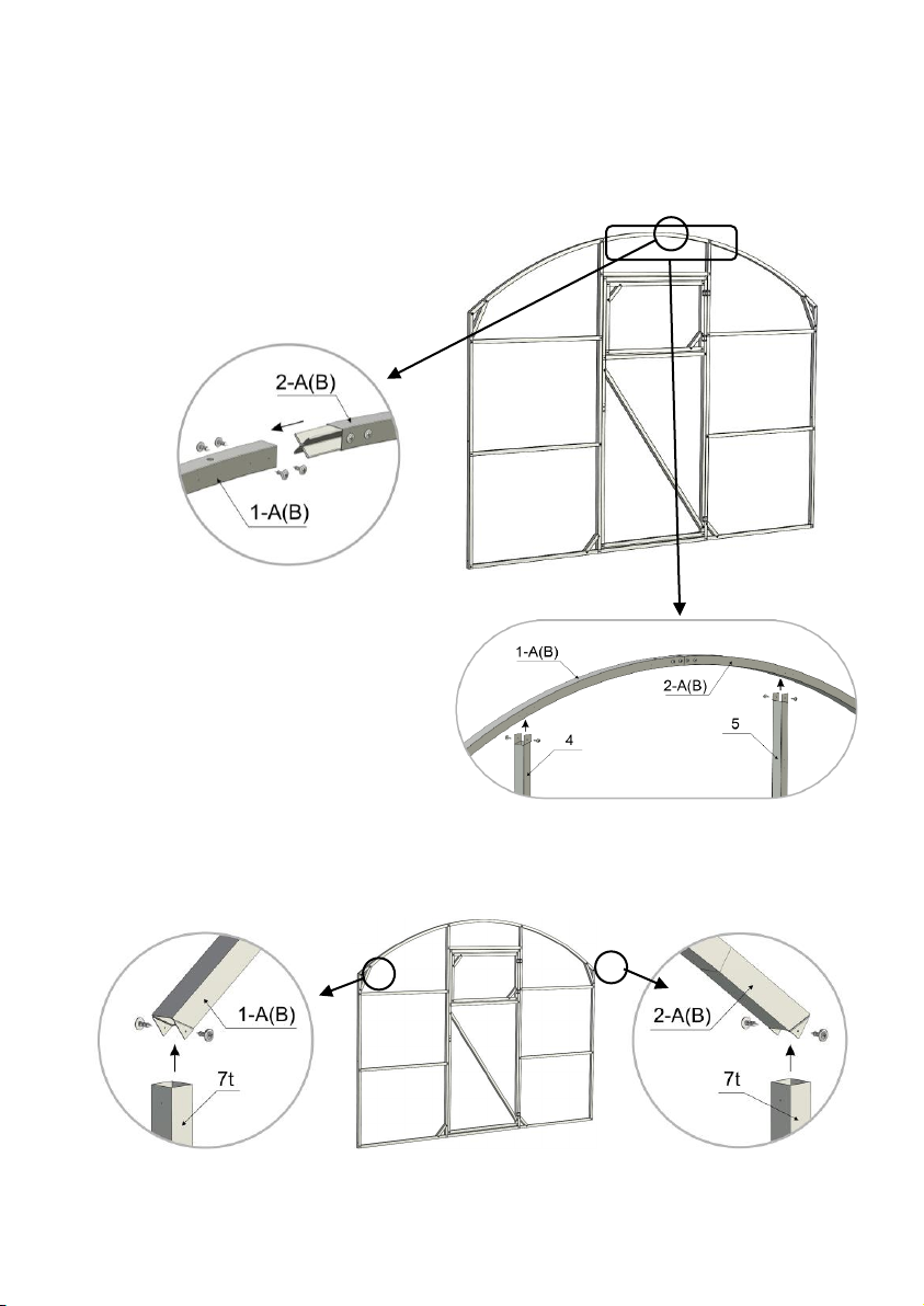
transverse rib of end-face, 1050mm
Middle part of the bottom transverse
rib of the end-face, 900mm
The right-hand part of the bottom
transverse rib of end-face, 1050mm
Grouser post, 20х20х250mm
Intermediate arch half-arc, left-hand
1605mm
Intermediate arch half-arc, right-hand,
1605mm
Intermediate arch diagonal tie,700mm
Door lintel, middle/bottom, 905mm
Door post, left-hand, 1780 mm
Door post, right-hand, 1780mm
Air gate lintel, top/bottom, 850mm
Air gate post, left-hand, 470mm
Air gate post, right-hand, 470mm
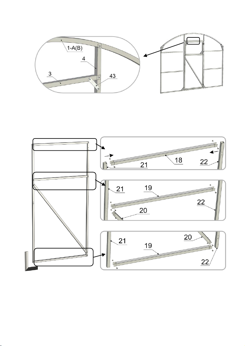
Longitudinal starting stringer,
2012mm
Longitudinal stringer with X-crimp,
2068mm
Angle piece, side 120°, 2025mm
Angle piece, end-face 90°, 1600mm
Self-tapping screw 4,2х16mm
(To assemble framework)
Self-tapping screw 4,2х19mm
(for polycarbonate fastening)
Thermal-washer with cover cap
Door/Air gate hand lever:
Hand lever –1 pc.; shield–1 pc.;
Locking point –1 pc.; screw М5 –
2pcs.; nut М5 – 2 pcs.