manuals.online logo
Brands
  1. Home
  2. •
  3. Brands
  4. •
  5. Velleman
  6. •
  7. Power Supply
  8. •
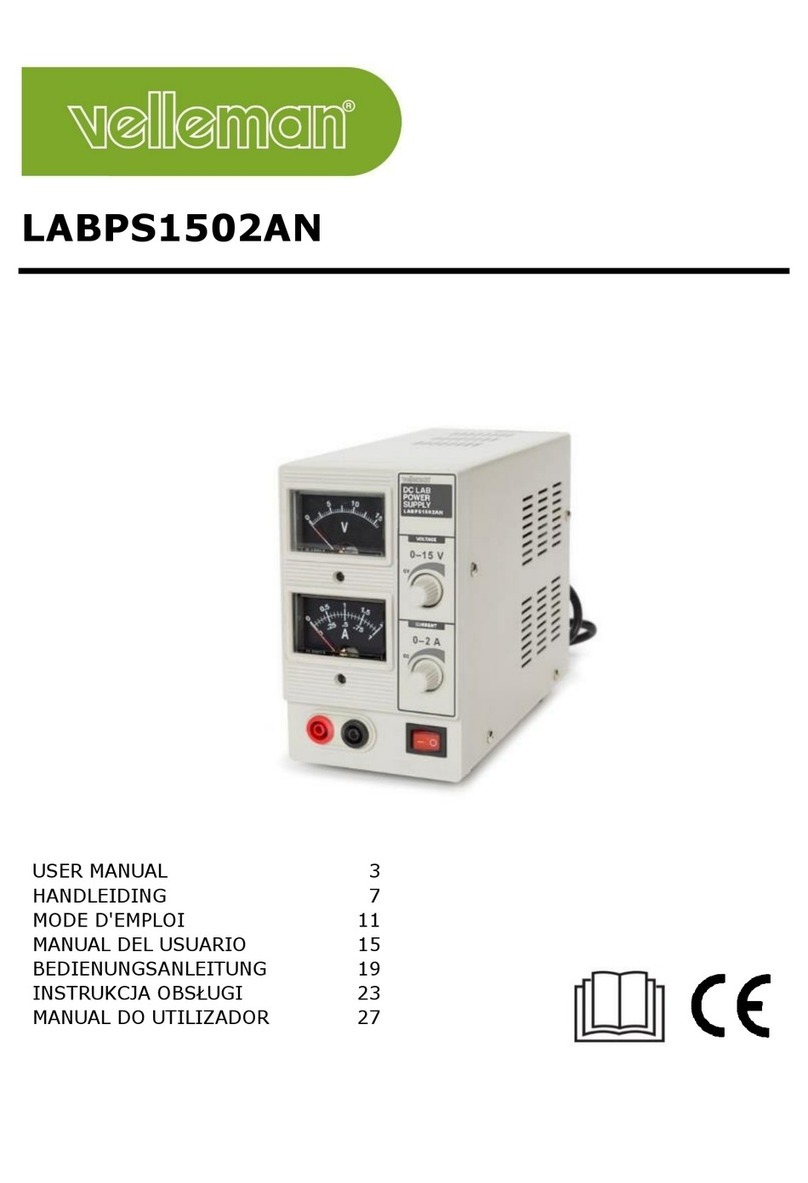
  9. Velleman High-Q Velleman-Kit K4006 User manual

Velleman High-Q Velleman-Kit K4006 User manual

Power supply for K4004B and K4005B
K4006
ILLUSTRATED ASSEMBLY MANUAL H4006IP-1
Total solder points: 36
Difficulty level: beginner 12345 advanced
Power supply for K4004B and K4005B
K4006
ILLUSTRATED ASSEMBLY MANUAL H4006IP-1
Total solder points: 36
Difficulty level: beginner 12345 advanced
2
Assembly hints
1. Assembly (Skipping this can lead to troubles ! )
Ok, so we have your attention. These hints will help you to make this project successful. Read them carefully.
1.1 Make sure you have the right tools:
• A good quality soldering iron (25-40W) with a small tip.
• Wipe it oftenon a wet sponge or cloth, to keep it clean; then apply solderto the tip, togive it a wetlook. This is called‘thinning’and will
protect the tip, and enables you to make goodconnections. When solder rolls off the tip, it needs cleaning.
• Thin raisin-core solder. Do not use any flux or grease.
• A diagonal cutter to trim excess wires. To avoid injury when cutting excess leads, hold the lead so they
cannot fly towards the eyes.
• Needle nose pliers, for bending leads, or to hold components in place.
• Small blade and Phillips screwdrivers. A basic range is fine.
For some projects, a basic multi-meter is required, or might be handy
1.2 Assembly Hints :
⇒ Make sure the skill level matches your experience, to avoid disappointments.
⇒ Follow the instructions carefully. Read and understand the entire step before you perform each operation.
⇒ Perform the assembly in the correct order as stated in this manual
⇒ Position all parts on the PCB (Printed Circuit Board) as shown on the drawings.
⇒ Values on the circuit diagram are subject to changes.
⇒ Values in this assembly guide are correct*
⇒ Use the check-boxes to mark your progress.
⇒ Please read the included information on safety and customer service
* Typographical inaccuracies excluded. Always look for possible last minute manual updates,indicated as ‘NOTE’on a separate leaflet.
0
.0
0
0
2
Assembly hints
1. Assembly (Skipping this can lead to troubles ! )
Ok, so we have your attention. These hints will help you to make this project successful. Read them carefully.
1.1 Make sure you have the right tools:
• A good quality soldering iron (25-40W) with a small tip.
• Wipe it oftenon a wet sponge or cloth, to keep it clean; then apply solderto the tip, togive it a wetlook. This is called ‘thinning’and will
protect the tip, and enables you to make goodconnections. When solder rolls off the tip, it needs cleaning.
• Thin raisin-core solder. Do not use any flux or grease.
• A diagonal cutter to trim excess wires. To avoid injury when cutting excess leads, hold the lead so they
cannot fly towards the eyes.
• Needle nose pliers, for bending leads, or to hold components in place.
• Small blade and Phillips screwdrivers. A basic range is fine.
For some projects, a basic multi-meter is required, or might be handy
1.2 Assembly Hints :
⇒ Make sure the skill level matches your experience, to avoid disappointments.
⇒ Follow the instructions carefully. Read and understand the entire step before you perform each operation.
⇒ Perform the assembly in the correct order as stated in this manual
⇒ Position all parts on the PCB (Printed Circuit Board) as shown on the drawings.
⇒ Values on the circuit diagram are subject to changes.
⇒ Values in this assembly guide are correct*
⇒ Use the check-boxes to mark your progress.
⇒ Please read the included information on safety and customer service
* Typographical inaccuracies excluded. Always look for possible last minute manual updates,indicated as ‘NOTE’on a separate leaflet.
0
.0
0
0
3
Assembly hints
1.3 Soldering Hints :
1- Mount the component against the PCB surface and carefully solder the leads
2- Make sure the solder joints are cone-shaped and shiny
3- Trim excess leads as close as possible to the solder joint
REMOVE THEM FROM THE TAPE ONE AT A TIME !
AXIAL COMPONENTS ARE TAPED IN THE COR-
RECT MOUNTING SEQUENCE !
You will find the colour code for the resistances and the LEDs in the HALG
(general manual) and on our website: http://www.velleman.be/common/service.aspx
4
 R1 : 2K7 (2 - 7 - 2 - B)
 R2 : 2K7 (2 - 7 - 2 - B)
1. 1W ResistorsR...
 F1 : 6,3A slow
 F2 : 6,3A slow
4. Fuse + fuseholder
F...
 LD1
 LD2
2. LEDs. Watch the polarity!
LD...
CATHODE
 C3 : 10.000µ F

C4 : 10.000µ F

C1 : Optional

C2 : Optional
Ordernr C1 & C2 : 10000LPOJ
7. Electrolytic Capacitors.
Watch the polarity !
C...
 J1
3. Screw terminal
 -V (2x)
 GND (2x)
 +V (2x)
5. PCB mounting tab
 B1 : RS603
(6A - 200V)
Watch the polarity!
6. Bridge rectifier

6 x
8. Flat receptacle
Wire
Insulation sleeve
Flat receptacle
Construction
5
Connection
K4004B,
K4005B
+V
GND
-V
K4006
+V
GND
-V
Speaker Power supply Transformer
K4005B 2 x 8 ohm 2 x 30VAC / 225VA Type 22530
K4005B 2 x 4 ohm 2 x 21VAC / 300VA Type 30021
K4005B 1 x 8 ohm 2 x 21VAC / 300VA Type 30021
K4004B 2 x 8 ohm 2 x 18VAC / 160VA Type 16018
K4004B 2 x 4 ohm 2 x 18VAC / 225VA Type 22518
K4004B 1 x 8 ohm 2 x 18VAC / 225VA Type 22518
Needs transformer :
9. Connection
6
10. PCB layout.
PCB
6
10. PCB layout.
PCB
7
11. Diagram
Diagram
7
11. Diagram
Diagram
Modifications and typographical errors reserved
© Velleman Components nv.
H4006IP - 2004 - ED1
VELLEMAN Components NV
Legen Heirweg 33
9890 Gavere
Belgium Europe
www.velleman.be
www.velleman-kit.com
5
4
1
0
3
2
9
3115
7
5
Modifications and typographical errors reserved
© Velleman Components nv.
H4006IP - 2004 - ED1
VELLEMAN Components NV
Legen Heirweg 33
9890 Gavere
Belgium Europe
www.velleman.be
www.velleman-kit.com
5
4
1
0
3
2
9
3115
7
5

Other Velleman Power Supply manuals

Velleman K8017 User manual

Velleman

Velleman K8017 User manual

Velleman PS613 User manual

Velleman

Velleman PS613 User manual

Velleman PS3005D User manual

Velleman

Velleman PS3005D User manual

Velleman LABPS3003 User manual

Velleman

Velleman LABPS3003 User manual

Velleman LABPS1502AN User manual

Velleman

Velleman LABPS1502AN User manual

Velleman PS1502A User manual

Velleman

Velleman PS1502A User manual

Velleman LABPS3005SM User manual

Velleman

Velleman LABPS3005SM User manual

Velleman LABPS3003SMU User manual

Velleman

Velleman LABPS3003SMU User manual

Velleman PSSE10 User manual

Velleman

Velleman PSSE10 User manual

Velleman FPS1306SM User manual

Velleman

Velleman FPS1306SM User manual

Velleman PS1503SB User manual

Velleman

Velleman PS1503SB User manual

Velleman HQ-Power PSS6EMV25 User manual

Velleman

Velleman HQ-Power PSS6EMV25 User manual

Velleman LABPS3020SM User manual

Velleman

Velleman LABPS3020SM User manual

Velleman 5410329595289 User manual

Velleman

Velleman 5410329595289 User manual

Velleman PS920 User manual

Velleman

Velleman PS920 User manual

Velleman LABPS23023 User manual

Velleman

Velleman LABPS23023 User manual

Velleman K7200 User manual

Velleman

Velleman K7200 User manual

Velleman PS5005 User manual

Velleman

Velleman PS5005 User manual

Velleman HQ-Power PS1320 User manual

Velleman

Velleman HQ-Power PS1320 User manual

Velleman LABPS3005N User manual

Velleman

Velleman LABPS3005N User manual

Velleman FPS1310 User manual

Velleman

Velleman FPS1310 User manual

Velleman LABPS1503U User manual

Velleman

Velleman LABPS1503U User manual

Velleman VMB4RY User manual

Velleman

Velleman VMB4RY User manual

Velleman LABPS3010SM User manual

Velleman

Velleman LABPS3010SM User manual

Popular Power Supply manuals by other brands

Meyer Sound MPS-488HP operating instructions

Meyer Sound

Meyer Sound MPS-488HP operating instructions

Basalte PUCK installation manual

Basalte

Basalte PUCK installation manual

Memco C100 Base 4 installation guide

Memco

Memco C100 Base 4 installation guide

Jedia JEP-352U operating instructions

Jedia

Jedia JEP-352U operating instructions

Altronix AL1024NK1 installation guide

Altronix

Altronix AL1024NK1 installation guide

EVGA SuperNOVA 1600 G2 user manual

EVGA

EVGA SuperNOVA 1600 G2 user manual

SDMO ineo 3000 Instruction and maintenance manual

SDMO

SDMO ineo 3000 Instruction and maintenance manual

Conrad 1233682 operating instructions

Conrad

Conrad 1233682 operating instructions

Anker 7 Series user manual

Anker

Anker 7 Series user manual

Whelen Engineering Company UPS64LX installation guide

Whelen Engineering Company

Whelen Engineering Company UPS64LX installation guide

PS Audio UPC-HB Power Center Owner's reference

PS Audio

PS Audio UPC-HB Power Center Owner's reference

Makita ADP08 Original instructions

Makita

Makita ADP08 Original instructions

Storz LED nova 150 instruction manual

Storz

Storz LED nova 150 instruction manual

Siemens SIMATIC ET200SP PS 6EP7133-6AB00-0BN0 24 V/5... manual

Siemens

Siemens SIMATIC ET200SP PS 6EP7133-6AB00-0BN0 24 V/5... manual

Flash SO/PPS300W instruction manual

Flash

Flash SO/PPS300W instruction manual

Tektronix Keithley 2231A-30-3 Performance Verification Guide

Tektronix

Tektronix Keithley 2231A-30-3 Performance Verification Guide

AWA HP-23 Upgrade instructions

AWA

AWA HP-23 Upgrade instructions

Kontron PD14 Product documentation

Kontron

Kontron PD14 Product documentation

manuals.online logo
manuals.online logoBrands
  • About & Mission
  • Contact us
  • Privacy Policy
  • Terms and Conditions

Copyright 2025 Manuals.Online. All Rights Reserved.