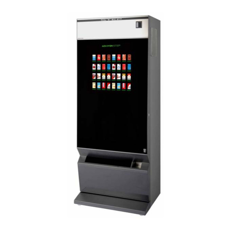
VendNet SM VI 3157 User manual

SEPTEMBER 2000 P/N 4211051
Rev B
Model:
3157
3158
3159
Service
Manual
SNACK FOOD
VENDOR
(SM VI)

ii SM VI, 3145, 3146, 3147, P/N 4211051
TABLE OF CONTENTS:
SPECIFICATIONS..................................1
INTRODUCTION ....................................1
UNPACKING..........................................3
INSTALLATION......................................4
COIN MECHANISM & BILL
VALIDATOR...........................................7
LOADING PRODUCTS..........................7
CHANGING TIMING AND
TRAY SPACING.....................................8
CONTROLLER FUNCTIONS.................9
Sales Mode........................................9
Service Mode...................................11
MENU 1 ...........................................13
MOTOR MODE...........................14
ACCOUNT MODE.......................15
COIN MODE................................17
TEST VEND MODE ....................18
MENU 2........................................... 19
PRICE MODE............................. 19
OPTIONS MODE........................ 21
PROMO VEND MODE................ 22
CONFIGURATION
MODE......................................... 23
MENU 3........................................... 24
POS/AUX MODE........................ 24
TIME/DATE MODE..................... 26
SHUTDOWN MODE................... 28
TEMPERATURE MODE
(not used with this
vendor)........................................ 29
DISCOUNT MODE ..................... 33
AUTO-
REINSTATEMENT
MODE......................................... 34
COUPON/TOKEN
MODE......................................... 35
CAN/BOTTLE MODE
(Not Used With This
Vendor)....................................... 36
DEX/UCS......................................... 38
CARE & CLEANING............................ 39
PARTS ORDERING............................. 40
SCHEMATIC........................................ 42
KEYPAD OVERLAY............................ 44
Record the Model Number and Serial Number of your machine below.
The Model and Serial numbers will be needed for you to obtain quick service and parts
information for your machine. The numbers are available on the identification plate
located on the back side of the cabinet of the machine.
MODEL NUMBER:______________________________________________________
SERIAL NUMBER:______________________________________________________

SM VI, 3157, 3158, 3159, P/N 4211051 1
SPECIFICATIONS
General Dimensions
INCHES CENTIMETERS
HEIGHT 3W, 4W, 5W 72 183
3W 28 1/2 72.4
4W 34 1/4 87
WIDTH
5W 40 1/8 102
DEPTH 3W, 4W, 5W 34 86
Lbs Kgs
3W 478 217
4W 500 227
APROXIMATE
WEIGHT 5W 568 258
Electrical
Power 115 VAC 230 VAC
Cycle 60 Hz 50 Hz
Current 1.2 Amps 0.6 Amps
Pricing
MDB Controller & Coin Mechanism
Recommended Maximum Product Size
INCHES MILLIMETERS
Large Snack Helix 5-27/32 x 1-1/2 x 9 148 x 38 x 228.6
Medium Snack Helix 4-3/8 x 1-1/2 x 7 111.1 x 38 x 178
Sandwich Cracker Helix 2-15/16 x 15/16 x 5-1/2 74.6 x 23.8 x 139.7
Gum/Mint Split Helix 1 x 13/16 x 5-1/2 25.4 x 20.6 x 139.7

2SM VI, 3157, 3158, 3159, P/N 4211051
INTRODUCTION
This manual contains service and installation guidelines and instructions for the Snack
Food Vendor product line.
All Snack Food Vendor models are equipped with an electronic control system. All
programming of the vend functions, pricing and features is done at the controller.
Changes can be made without any additional accessories or remote parts.
Selections can be priced individually from Free to $999.95 in five cent increments (U.S.
currency).
Features include:
•Multi Drop Bus (MDB) coin handling mechanism
•Self-diagnostics and cash accountability
•Multi Vend, Free Vend, Bonus Vend and Promo Vend features
•Motorized delivery, electronically controlled
CAUTION:
This vendor utilizes DC motors. Do not attempt to turn augers by hand.
Motor damage could occur.
•Visual feedback when a product has been vended or when an error condition
exists.
•No change or loss of program/memory as a result of power failure
•Cash accountability records Total Cash transactions and Total Vend cycles
performed by the vendor. Information for individual selections, complete range
(rows) or total machine can be compiled and used for inventory and ordering
records
The vending sequence is "first-in, first-out" for each selection, eliminating the need for
stock rotation to maintain fresh products in the vend area.
This manual should be read thoroughly to become familiar with the functions of all
components, along with the features that are available. The initial set-up of a vending
machine is very important in insuring trouble-free operation of the equipment. Following
the instructions at the initial installation of the machine will avoid service problems and
minimize set-up time.
Should you have any questions pertaining to information in the manual, replacement
parts or the operation of the vendor you should contact your local distributor or:
Vendnet
165 North 10th Street
Waukee, Iowa 50263 - USA
Service:800-833-4411
Parts:888-259-9965
AllOthers:888-836-3638
Fax:515-987-4447
E-mail: Vendnet@vendnetusa.com

SM VI, 3157, 3158, 3159, P/N 4211051 3
UNPACKING
This vendor was thoroughly inspected before leaving the factory and the delivering
carrier has accepted responsibility for this vendor. Note any damage or irregularities at
the time of delivery and report them to the carrier. Request a written inspection report
from the claims inspector to file any claim for damage. File the claim with the carrier
(not the manufacturer) within 15 days after receipt of the machine.
Carefully remove outside packing material to avoid damage to the finish or exterior of
the machine. Remove adhesive residue with denatured alcohol or common household
vinegar.
Inspect the machine for concealed shipping damage. Report any damage hidden by the
shipping material directly to the delivering carrier on a hidden damage report.
Record the model number and serial number of the vendor for your records. These
numbers can be found on the Serial Plate on the rear of the cabinet and/or inside the
vendor. Refer to these numbers on all correspondence and inquiries pertaining to this
vendor.
WARNING
Use caution when tipping machine from pallet. Machine is heavy and can
fall causing serious injury. This may require a second person.
Remove the two (2) retaining blocks from the shipping pallet. See Figure 1. Slide the
vendor forward on the pallet until the front legs are clear of the pallet. See Figure 2. Tilt
the vendor to the front until the rear legs are clear of the palllet and remove the pallet.
See Figure 3. Turn the leg leveling screws in as far as possible. See Figure 4.
Figure 1. Retaining Blocks Figure 2. Slide Forward
Figure 3. Tilt to Clear Rear Legs Figure 4. Leg Levelers
A10721 A10722
A10723 A10724

4SM VI, 3157, 3158, 3159, P/N 4211051
INSTALLATION
Consult local, state and country codes and regulations before installation of the vendor.
CAUTION:
To insure reliability and maintain manufacturers equipment warranty,
machine must NOT be placed in an environment where the temperature
is greater than 90°
°°
°F/32°
°°
°C and the relative humidity is 65% or greater.
1. Position the vendor in its place of operation no further than six (6) feet
(2 m) from the power outlet or receptacle.
WARNING:
DO NOT USE EXTENSION CORDS.
Extension cords can cause problems. Noise on the line. Shorts, low
voltage, etc.
2. Leave at least six (6) inches (15 cm) of space between the back of the machine
and any wall or obstruction for proper air circulation.
3. Retrieve the keys to the vendor from the coin return cup.
4. Open outer door and remove all internal packing material.
5. Check that the door will open fully without interference.
6. Level the vendor, making sure all levelers are touching the floor. The vendor must
be level for proper operation and acceptance of coins through the coin mechanism.
When the vendor is level, the door can be opened to any position and not move by
itself. Try the door half closed, straight out and in the wide open position before
deciding the vendor is level.
Grounding (Earthing) & Electrical
Before connecting the vendor, the integrity of the main electrical supply must be
checked for correct polarity, presence of ground (earth) and correct voltage. These
checks should be repeated at 6-month intervals with the routine safety electrical
testing of the vendor itself.
For proper operation of any equipment utilizing electronically controlled components,
the equipment should be placed on an isolated or dedicated noise-free circuit.
A noise suppressor has been installed in this machine to compensate for any signal
noise that could interfere with the normal operation of the controller.
For 115-Volt vendors the circuit should be a minimum 15 Amp, 60 cycle, properly
polarized and grounded (earthed).
For 230-Volt vendors the circuit should be a minimum 7.5 Amp, 50 cycle, properly
polarized and grounded (earthed).
Shown in Figure 5 and Figure 6 are two properly grounded (earthed) and polarized wall
outlets. Figure 5 shows two 230-Volt wall outlets.
SM VI, 3157, 3158, 3159, P/N 4211051 5
Figure 5. 230-Volt Outlets Figure 6. 115-Volt Outlet
Connect the vendor power cord to a grounded 115 Volt AC, 60 Cycle, noise free
polarized power source of not less than 15 Amps. Checking the power source can be
accomplished with an AC Voltmeter in the following manner:
1. Voltage Check
When the AC Voltmeter probes are
connected to the HOT and NEUTRAL
terminals, the voltmeter should
indicate 110 to 130 volts AC. See
Figure 7.
2. Polarity and Ground Check
When the AC Voltmeter probes are
connected to the HOT and GROUND
terminals, the voltmeter should
indicate 110 to 130 Volts AC. See
Figure 7.
Figure 7. Electrical Check with Voltmeter
3. Noise Potential Check
When the AC Voltmeter probes are connected to the NEUTRAL and GROUND
terminals, the voltmeter should indicate 0 Volts AC. See Figure 6. Any voltage
reading could cause noise problems in the electronic controller.
4. Amperage Check
At the fuse box or circuit breaker panel, locate the proper circuit and ensure that
the fuse or breaker protecting that circuit is rated at 15 Amps or greater.
In a standard three (3) prong 115 Volt AC wall outlet the GROUND pin is round, the
NEUTRAL pin is rectangular and located clock-wise from the ground pin and the
HOT pin is rectangular and smaller than the neutral pin and located
counterclockwise from the ground pin. See Figure 7.
To correct negative voltage, amperage, polarity, or ground checks, consult a licensed
electrician. To correct a negative noise potential check, install a noise suppressor which
can be obtained from any electrical or electronic supply store or in kit form.
A10161
A10100
NOT
E
NOTENOT
E
NOTE
A10116

6SM VI, 3157, 3158, 3159, P/N 4211051
Outlet Tester
An easy to read outlet tester can be obtained
from Vendnet (P/N 4211746) or any
electrical or electronic supply store.
Plug the tester into any grounded (3-prong)
115V AC outlet to detect faulty wiring. See
Figure 8.
Read the indicator lights as explained on the
tester. See Table 1 for explanation of faults.
Refer all indicated problems to a qualified
electrician.
CAUTION
Unplug all equipment on branch circuit before testing.
This is not a comprehensive diagnostic instrument. Please refer to the tester
packaging for more information.
Table 1. Indicated Problems when using a tester
FAULT REASON FOR FAULT
Open Ground Ground contact not connected
Open Neutral Neutral contact not connected
Open Hot Hot contact not connected
Hot Ground Reverse Hot and ground contacts interchanged
Hot Neutral Reverse Hot and neutral contacts interchanged
Power Switch
Each vendor is equipped with a power
switch located on the power panel along
with a 3-Amp and a 5-Amp breaker. The
switch will shut-off the controller. See
Figure 9.
The 3-Amp breaker is protection for the
transformer.
The 5-Amp breaker is protection for the
entire vendor.
Figure 9. Power Switch, Breakers
Figure 8. 3-Prong Outlet Teste
r
A10593
NOT
E
NOTENOT
E
NOTE
A10733
POWER SWITCH &
BREAKERS

SM VI, 3157, 3158, 3159, P/N 4211051 7
COIN MECHANISM & BILL VALIDATOR
CAUTION:
Do not plug in or unplug the coin changer with the power on!
The controller will monitor the condition of the coin changer at all times. Any activity
(coins inserted) will be recorded and stored in the controller.
Removing Accepted Bills
Accepted bills may be removed by opening the “bill box” lid or by removing the bill box
from the validator. (See manual from validator manufacturer).
If the bill box is removed, make sure that it is fully latched in place when it is returned
to the validator.
Clearing Jams & Cleaning
Trapped bills, debris or dirt can result in poor bill acceptance or bill rejection. Remove
the bill box and lower housing to clear trapped bills or debris. Clean the bill path plastic
parts or belts with a cloth moistened with a mild soap and water solution. Clean the
magnetic head and optic sensors using a swab and isopropyl alcohol. (See manual
from validator manufacturer)
CAUTION:
Do not use any petroleum based cleaning solvents, scouring pads or stiff
brushes for cleaning.
LOADING PRODUCTS
To load products, lift tray slightly and pull
forward until the tray stops. The upper-most
trays will tilt for ease of loading.
Load products from front to back, making
sure all items fit freely between the augers.
Do not attempt to force oversize items or
packages into the spaces. Do not skip a
space. The bottom of the package should be
placed on the bottom of the compartment
above the product augers. The label should
face the front of the machine for easy
identification by the customer. See Figure
10. Figure 10. Loading Products
NOT
E
NOTENOT
E
NOTE
A10114

8SM VI, 3157, 3158, 3159, P/N 4211051
When finished loading each tray, make sure the tray is returned to its proper standby
position. All trays must be pushed to the rear of the cabinet and properly seated in the
"detent" position.
The size of the item being vended must be larger than the diameter of the auger being
used to vend properly. Undersized items could cause vend problems. If the product
does not fit the auger properly, it is recommended that a different auger be used.
Optional augers are available; see the “Parts Ordering Procedure” (page 49) section for
ordering information.
Product Ejectors
Product ejectors can be added
to the end of the augers to help
move the product out of the tray
area (see Figure 11). Order P/N
4025748.
Figure 11. Product Ejectors
CHANGING TIMING AND TRAY SPACING
Retiming the augers can dispense difficult-to-vend items more dependably. Larger
items can be vended by altering tray spacing.
Timing
Each auger can be rotated in 20-degree increments for a different drop-off point. Most
items can be vended successfully when the auger end is positioned at 6 o'clock.
To change the auger end positions:
1. Make sure the auger coupling is seated
over the vertical rail or retaining rib on the
tray.
2. Remove the motor cover.
3. Raise the motor slightly and pull forward
on the auger until it separates from the
motor. See Figure 12.
4. Rotate the auger to the desired position
and re-insert the auger coupling into the
motor.
5. Replace the motor cover and securely
tighten. Figure 12. Auger Motor assembly
A10085
A10112

SM VI, 3157, 3158, 3159, P/N 4211051 9
Tray Spacing
The trays can be raised or lowered in 1-inch (25.4 mm) increments to provide additional
headroom for vending taller items.
When increasing the space between two trays, a corresponding decrease in space
of an adjoining tray will result.
To change tray spacing, follow the steps outlined below:
1. Pull out the tray to be adjusted until it stops.
2. Disconnect the tray plug from its receptacle on the right side wall.
3. Lift up on the rear of the tray and remove it from the machine.
4. Disengage both left and right tray rails from their corresponding slots on the left
and right sides.
5. Relocate both left and right rails.
Rails must be level front to back and right to left.
6. Replace the tray by placing its rear rollers on the left and right rails and lifting up on
the front of the tray as you push it back.
7. Install the tray harness plug into its receptacle on the right side.
8. Test vend the tray in its new position to assure that the tray harness plug is
properly connected.
CONTROLLER FUNCTIONS
There are two modes of operation.
Sales Mode: The vendor accepts deposits, pays out change, and dispenses product to
the customer. The 10-character scrolling display is used to communicate with the
customer.
Service Mode: Used by the operator to program and service the machine. The display
is used to communicate with the operator.
Sales Mode
Display and Vend Cycle
When no credit has been established and a selection is made, the price for that
selection displays for approximately one second.
When credit is deposited the amount displays. Five digits are available.
After a selection is made, the controller will determine if sufficient credit is available. If
the accumulated credit is greater than or equal to the price of the selection a vend
NOTE
NOTE

10 SM VI, 3157, 3158, 3159, P/N 4211051
attempt will take place. If credit is less than the selection price, the price will display will
scroll
please
pleaseplease
please
insert
insertinsert
insert
more
moremore
more
money
moneymoney
money
.
After a successful vend, the amount of change to be returned will be displayed until all
coinage is paid back.
If a selection is made and a vend cannot take place, or selection is empty, (assuming
that sufficient credit and change are available) the
MAKE ALTERNATE
MAKE ALTERNATEMAKE ALTERNATE
MAKE ALTERNATE
SELECTION
SELECTIONSELECTION
SELECTION
message scrolls.
If the payout tubes in the coin mechanism are below the low-level sensors, the
USE
USEUSE
USE
CORRECT CHANGE
CORRECT CHANGECORRECT CHANGE
CORRECT CHANGE
message will scroll.
If no motors have been assigned or if the motor has been recorded as faulty, the
MAKE ALTERNATE SELECTION
MAKE ALTERNATE SELECTIONMAKE ALTERNATE SELECTION
MAKE ALTERNATE SELECTION
message scrolls.
Jammed Motor Condition
The controller will not run motors that have been recorded as “jammed” or have not
been assigned. A motor jam is detected when power is applied to a motor and the
motor fails to return to the home position within about 9 seconds.
Motors recorded as inoperative can be reset by running a test vend of that particular
selection. See the Test Vend Selections section of this manual (page 18).
Vend and Cash Counters
Following a successful vend, the vend counter will be incremented by one (1) and the
cash counter will be incremented by the price of the vended selection. The counter
rollovers occur at 79,999,920 vends and $9,999.95 respectively.
Test vends are not included in the counter totals.
Resettable Vend and Cash Counters
The resettable counters track Total Vends dispensed and Total Cash collected since
last reset. The vend count and cash totals will be available by individual selections,
range (rows) and entire machine utilizing all the rows (i.e. row A to row J for the
vendor).
Following a successful vend, the resettable vend counter will be incremented by one (1)
and the resettable cash counter will be incremented by the price of the selection
vended. The counter rollovers occur at 79,999,920 vends and $9,999.95 respectively if
never reset.
Test vends are not included in the counter totals.
NOTE
NOTE

SM VI, 3157, 3158, 3159, P/N 4211051 11
Service Mode
Entering the Service Mode
To change any settings or programs in the vendor, the
controller must be placed in the Service Mode. To enter the
Service Mode, push the red service mode button once (located
on the control board). If credit exists when entering the Service
Mode, it will be restored when the machine is returned to the
Sales Mode.
Key Functions while in Service Mode:
Key ( A ) = Scrolls UP through a menu, sub-menu
Key ( B ) = ENTERS a menu, sub-menu or routine within a
menu
Key ( C ) = Scrolls DOWN through a menu, sub-menu
Key ( D ) = SAVES a change within sub-menus or routines
Key ( E ) = EXITS down a level from a menu, sub-menu or
routine without making a change.
The following three diagrams illustrate the three menu levels and the sub-menu levels
of each main menu. Use the ( A ) (moves clockwise through circle diagrams) and ( C )
(moves counterclockwise through circle diagrams) keys to scroll through each menu or
sub-menu. Use the ( A ) key to move from menu to sub-menu levels.
A10686

12 SM VI, 3157, 3158, 3159, P/N 4211051
A10687
A10688

SM VI, 3157, 3158, 3159, P/N 4211051 13
A quick way to access Menu levels 2 & 3:
Press Service Mode Button.
Diagnose
DiagnoseDiagnose
Diagnose
will display.
Press ( A ) to display
Menu 2
Menu 2Menu 2
Menu 2
. Press ( B ) to enter menu 2.
Price
PricePrice
Price
will display.
Press ( C ) to display
Menu 3
Menu 3Menu 3
Menu 3
. Press ( B ) to enter Menu 3.
POS/AUX
POS/AUXPOS/AUX
POS/AUX
will
display.
Upon entering Service Mode the display will show
Diagnose
DiagnoseDiagnose
Diagnose
,which marks the
beginning of MENU 1 of the Service Menu.
Pressing ( E ) will exit a menu or sub-menu item without saving any changes
Exiting the Service Mode
To exit the Service Mode, push the Service Mode Button.
The controller will automatically exit the Service Mode if no key is pressed for
approximately 25 seconds.
MENU 1
Press ( A ) or ( C ) to scroll through the Menu1 sub-Mode menu.
Diagnose Mode.......Displays Error codes
Motor Mode ............Counts and Configures motors
Account Mode.........Account Mode is used to display various types of cash and
vend totals
Coin Mode..............Coin mode is used to load or unload the coin mech coin tubes
and to set Unconditional Acceptance and Exact Change
Test Vend Mode .....Test Vend cycles each selection or range of selections to
assure that they are working properly
With
DIAGNOSE
DIAGNOSEDIAGNOSE
DIAGNOSE
displayed
Press ( B ) to enter Errors Mode.
VMC OK
VMC OKVMC OK
VMC OK
(Vendor Motor Configuration) will be
displayed.
Press ( B ) again to display error codes. If there are no errors, the display will scroll
through:
VMC
VMCVMC
VMC OK
OKOK
OK
Changer
ChangerChanger
Changer OK
OKOK
OK
Validat
ValidatValidat
Validat OK
OKOK
OK
Reader
ReaderReader
Reader OK
OKOK
OK
If the display reads for example: (
Reader 8
Reader 8Reader 8
Reader 8
) the controller can not locate a card
reader. See the following table for error codes.
Press ( E ) to return to
DIAGNOSE
DIAGNOSEDIAGNOSE
DIAGNOSE
display.
Press ( C ) to move to Motor Mode.
motor
motormotor
motor
will be displayed.
NOTE
NOTE
NOTE

14 SM VI, 3157, 3158, 3159, P/N 4211051
Error Codes
CODE DISPLAYS ERROR DETAIL
1
11
1
Too little motor current (under 20mA)
2
22
2
Too much time to complete vend (12 Seconds)
3
33
3
Coin Mechanism communication error
4
44
4
NOVRAM checksum error
5
55
5
Health and safety error on temperature sensor 1
6
66
6
Health and safety error on temperature sensor 2
7
77
7
Bill Validator communication error
8
88
8
Card Reader communication error
MOTOR MODE
Motor mode is used to display the number of working motors or to configure the
vendor to the currently working motors.
Press ( B ) to enter motors mode.
MOTORS
MOTORSMOTORS
MOTORS
will be displayed.
Press ( A ) or ( C ) to scroll through the Motor Mode sub-menu.
Motors........................... Motor Count of working motors
Configure....................... Configure vendor to working motors
Press ( B ) again to display the number of working motors.
Press ( E ) to return to the
MOTORS
MOTORSMOTORS
MOTORS
display.
Press ( C ) to enter configuration mode.
CONFIG
CONFIGCONFIG
CONFIG
will be displayed.
Press ( B ) to automatically configure machine to the currently working motors. After
a short pause
CONFigureD
CONFigureDCONFigureD
CONFigureD
will be displayed.
Press ( E ) to exit back to
CONFIG
CONFIGCONFIG
CONFIG
.
Press ( E ) again to return to
MOTOR
MOTORMOTOR
MOTOR
.
From there press ( C ) to move to Account mode.
Account
AccountAccount
Account
will display.
NOTE

SM VI, 3157, 3158, 3159, P/N 4211051 15
ACCOUNT MODE
Account Mode is used to display various types of cash and vend totals.
Press ( B ) to enter Account Mode
HIST SALES
HIST SALESHIST SALES
HIST SALES
will be displayed.
Press ( A ) or ( C ) to scroll through the Account Mode sub menu.
Historical Sales.............. Total sales since initialization
Historical Count............. Total vends since initialization
Reset Sales................... Total sales since last reset
Reset Count................... Total vends since last reset
RDR Sales..................... Card Reader Sales
Set Range ..................... Defines a range for cash and vend counts
Range Cash................... Total sales for defined range since last reset
Range Vends................. Total vends for defined range since last reset
Clear.............................. Clears all resettable counts above
HISTORICAL SALES
Displays the total amount of sales (by dollar) since initialization of the control
board.
Press ( B ) to display the amount of sales since initialization.
Press ( E ) to return to the
HIST SALES
HIST SALESHIST SALES
HIST SALES
display.
Press ( C ) to move to historical count.
HIST COUNT
HIST COUNTHIST COUNT
HIST COUNT
will be displayed.
HISTORICAL COUNT
Displays the total number of vended products since initialization of the control
board.
Press ( B ) to display vended products since initialization.
Press ( E ) to return to the
HIST COUNT
HIST COUNTHIST COUNT
HIST COUNT
display.
Press ( C ) to move to Resettable Sales.
RES SALES
RES SALESRES SALES
RES SALES
will be displayed.
RESETTABLE SALES
Displays the total sales (in dollars) since the last reset.
Press ( B ) to display the total sales.
Press ( E ) to return to the
RES SALES
RES SALESRES SALES
RES SALES
display.
Press ( C ) to move to Resettable Count.
RES COUNT
RES COUNTRES COUNT
RES COUNT
will be displayed.
RESETTABLE VEND COUNT
Displays the total vends since the last reset.
Press ( B ) to display number of vended products.
Press ( E ) to return to the
RES COUNT
RES COUNTRES COUNT
RES COUNT
display.
Press ( C ) to move to Card Reader Sales.
RDR SALES
RDR SALESRDR SALES
RDR SALES
will be displayed.
NOTE

16 SM VI, 3157, 3158, 3159, P/N 4211051
RDR SALES
Displays the total card reader sales.
Press ( B ) to display the Card Reader Sales. (optional hardware required).
Press ( E ) to return to the
RDR SALES
RDR SALESRDR SALES
RDR SALES
display.
Press ( C ) to move to Set Range.
SET RANGE
SET RANGESET RANGE
SET RANGE
will be displayed.
SET RANGE
The operator uses Set Range to define a specific range of selections to display
total cash or vends since last reset. Use the Range Cash or Range Vends below
to display totals. Ranges can only be defined by row and not by selections.
Press ( B ) to display
SR/ER
SR/ERSR/ER
SR/ER
and the current range. To change the range press the
letter of the first selection to be specified and then the letter of the last selection
to be specified. (For example: A – A for the top tray or A – C for the top three
trays).
Press ( D ) to save range and return to the
SET RANGE
SET RANGESET RANGE
SET RANGE
display.
Press ( C ) to move to Range Cash.
RANGE CASH
RANGE CASHRANGE CASH
RANGE CASH
will be displayed.
RANGE CASH
Displays the total sales (by dollar) for the defined range.
Press ( B ) to display total sales of the defined range.
Press ( E ) to return to the
RANGE CASH
RANGE CASHRANGE CASH
RANGE CASH
display.
Press ( C ) to move on to
RANGE VENDS
RANGE VENDSRANGE VENDS
RANGE VENDS
.
RANGE VENDS
Displays the number of vended products for the defined range.
Press ( B ) to display the number of vended products over the defined range.
Press ( E ) to return to the
RANGE VENDS
RANGE VENDSRANGE VENDS
RANGE VENDS
display.
Press ( C ) to move to Clear.
clear
clearclear
clear
will display.
CLEAR
Clears all resettable values.
Press ( B ).
Cleared
ClearedCleared
Cleared
will display.
Press ( E ) to return to the
clear
clearclear
clear
display.
Press ( E ) to exit Account sub-menu.
Account
AccountAccount
Account
will display
Press ( C ) to move to Coin Mode.
coin
coincoin
coin
will display.

SM VI, 3157, 3158, 3159, P/N 4211051 17
COIN MODE
Coin mode is used to load or unload the coin mech coin tubes and to set
Unconditional Acceptance and Exact Change values.
Press ( B ) to enter Coin mode.
CPO
CPOCPO
CPO
(Coin Pay Out) will be displayed
Press ( A ) or ( C ) to scroll through the Coin Mode sub-menu.
CPO .............................. Coin Tube Payout
Tube Fill......................... Displays current amount in coin tubes
Unconditional Accept..... Sets the value for Unconditional Acceptance
Exact Change................ Sets value for Exact Change
CPO (Coin Pay Out)
Pays out coins from the coin mech coin tubes.
Press ( B ) to display
DISPENSE
DISPENSEDISPENSE
DISPENSE
. Press the number ( 1 ) key to dispense least
significant coin, ( 2 ) key for next significant coin, or the ( 3 ) key for the most
significant coin. On some coin mechs there is a fourth tube (the dollar coin for
example). Use the number ( 4 ) key for this tube. Press and hold 1, 2, 3, or 4 to
rapidly dispense coins.
Press ( E ) to exit dispense and return to the
CPO
CPOCPO
CPO
display.
Press ( C ) to move to Tube Fill.
TUBE FILL
TUBE FILLTUBE FILL
TUBE FILL
will display.
TUBE FILL
Display will show an increasing total as coins are entered through the coin mech.
Press ( B ).
FILL COINS
FILL COINSFILL COINS
FILL COINS
will be displayed briefly, followed by
00.00.
00.00.00.00.
00.00.
The
display will change as coins are entered through the coin mech.
Manually ejecting coins will not subtract from the total. and exiting the Fill Coins
mode will reset the counter back to 00.00.
Press ( E ) to return to the
TUBE FILL
TUBE FILLTUBE FILL
TUBE FILL
display.
Press ( C ) to move to Unconditional Acceptance.
UNCON ACCP
UNCON ACCPUNCON ACCP
UNCON ACCP
will display.
UNCONDITIONAL ACCEPTANCE
Used to set the highest amount of currency in bills or coins that can be accepted
without regard if the equivalent value in coins can be returned.
Press ( B ) to display the amount currently set for unconditional acceptance.
Change amount using numerical keys.
Press ( D ) to save change and return to
UNCON ACCP
UNCON ACCPUNCON ACCP
UNCON ACCP
display.
Press ( C ) to move to Exact Change.
NOTE
NOTE

18 SM VI, 3157, 3158, 3159, P/N 4211051
EXACT CHANGE
Sets the Exact Change value that controls the display of the
Insert Exact
Insert ExactInsert Exact
Insert Exact
Change
ChangeChange
Change
message.
Press ( B ) to display the amount currently set for exact change.
Change amount using numerical keys. Press ( D ) to save change and return to
Exact
ExactExact
Exact
Change
ChangeChange
Change
.
Press ( E ) to exit Coin Mode sub-menu.
coin
coincoin
coin
will display.
Press ( C ) to move to Test Vend Mode.
test vend
test vendtest vend
test vend
will display.
TEST VEND MODE
Test Vend cycles each selection or range of selections to assure that they are
working properly - product will be vended in the process.
Press ( B ) to enter Test Vend Mode.
SELECTION
SELECTIONSELECTION
SELECTION
will be displayed.
Press ( A ) or ( C ) to scroll through the Test Vend Mode sub-menu.
Selection.................Test Vends one selection
Range.....................Test Vends a set range of selections
SELECTION
Use this option to test vend one selection at a time.
Press ( B ) to display
SELECT
SELECTSELECT
SELECT
and
-- --
-- ---- --
-- --
. Enter the desired selection (“B3” for
example). The current price of the chosen selection will be displayed and the
selection will vend. A triple beep indicates that the selection did not properly
vend. After the test vend, the display will return to
SELECTION
SELECTIONSELECTION
SELECTION
.
Press ( B ) to repeat process or press ( C ) to move to Range.
RANGE
Use this option to test vend a range of selections by rows at a time. The range is
settable by the operator.
Press ( B ) to display
SR/ER
SR/ERSR/ER
SR/ER
(Start Range/End Range) and the current range of
rows set to be automatically test vended. Change the range by entering the first
row to be tested followed by the last row to be tested.
(For example: “A - A” or “B - D”)
Press ( D ) to begin test vend. At the end of the test, the display will return to
TEST
TESTTEST
TEST
VEND
VENDVEND
VEND
.
Press ( C ) to move to MENU 2.
Menu 2
Menu 2Menu 2
Menu 2
will be displayed.
NOTE
This manual suits for next models
2
Table of contents
Other VendNet Vending Machine manuals
Popular Vending Machine manuals by other brands

Royal Vendors
Royal Vendors Merlin IV Service bulletin

Bag of Ice
Bag of Ice XL1900 product manual

Necta
Necta Canto Plus Espresso Installation operation & maintenance

Crane Merchandising Systems
Crane Merchandising Systems Autobar INFINITY Operator's manual

Westomatic
Westomatic EVOLVE installation guide

Westomatic
Westomatic EVOLVE manual